2021
C. J. O. \surReichhardt \orgdivTheoretical Division, \orgnameLos Alamos National Laboratory, \orgaddress\cityLos Alamos, \postcode87545, \stateNew Mexico, \countryUSA
Dynamic Phases and Reentrant Hall Effect for Vortices and Skyrmions on Periodic Pinning Arrays
Abstract
We consider the motion of superconducting vortices and skyrmions on a square substrate near the first commensurate matching field. Slightly above commensuration, a series of dynamic phases appear including interstitial flow, and there is a transition from fluid flow to soliton flow that generates negative differential conductivity. Slightly below commensuration, vacancy depinning occurs. The dynamic phase transitions produce features in the velocity-force curves, differential mobility, and velocity fluctuations. When a Magnus force is also present, as in certain superconducting vortex or skyrmion systems, there is an expansion of the fluid state, and at lower drives there is a finite Hall angle in the fluid phase but a vanishing Hall angle in the soliton phase, giving rise to a reentrant Hall effect. We also find a regime where the Hall motion of the particles exhibits the same dynamic phases, including soliton motion at a finite angle that produces negative differential conductivity in the Hall response but not in the longitudinal response. Our results suggest that vortices driven over periodic pinning may be an ideal system for determining if a vortex Hall effect is occurring and would also be relevant for skyrmions at smaller Magnus forces.
keywords:
superconducting vortex, skyrmion, periodic pinning, dynamic phases1 Introduction
Particles interacting with a substrate arise in a variety of both hard and soft condensed matter systems Bak82 ; Braun98 ; Reichhardt17 . The ratio of the number of particles to the number of substrate minima, known as the commensurability ratio or filling factor , is a useful measure when the substrate is periodic, and at the system is said to be commensurate Bak82 ; Baert95 ; Harada96 ; Reichhardt98 ; Brunner02 ; Berdiyorov06 ; Reichhardt17 . The substrate and particle arrangements normally have the same symmetry under commensurate conditions; however, when the coupling to the substrate is weak, interactions among the particles can favor other kinds of ordering Reichhardt17 ; Brazda18 . Under an applied drive, the depinning force, friction, and flow phases depend strongly on the commensurability ratio Bak82 ; Reichhardt97 ; Braun98 ; Bohlein12 ; Vanossi12 ; Vanossi13 ; Reichhardt17 . Just at commensuration, all the particle-particle interactions cancel due to symmetry and the depinning force reaches a maximum value. On the other hand, if the system is slightly above or below commensuration, solitons or kinks can appear in the commensurate lattice that depin before the rest of the particles, strongly depressing the depinning threshold, and in some cases multiple depinning transitions can occur in which the depinning of kinks or anti-kinks is followed by depinning of the commensurate particles Reichhardt17 ; Bohlein12 ; Vanossi12 . For egg-carton or sinusoidal potentials, which can be created optically, via lithographic pattering, or through the periodic ordering of atoms on a surface Bohlein12 ; Vanossi12 ; Hasnain13 ; Reichhardt17 , the kinks act like quasiparticles that are localized above the commensurate lattice. It is also possible to create periodic muffin tin potentials that have well-defined trapping sites separated by extended flat regions Baert95 ; Harada96 ; Reichhardt98 . Such substrates have been realized for vortices in superconductors in the form of holes Baert95 ; Harada96 or magnetic dots Martin97 , as well as for colloidal Mangold03 and skyrmion systems Reichhardt15a ; Saha19 .
On either side of for the muffin tin substrate, incommensurations take the form of interstitial particles for or vacancies for . The interstitials appear when all of the pinning sites are occupied and the additional particles sit in the flat part of the potential landscape between the occupied pinning sites. These interstitial particles can still be pinned through their interactions with the particles at the pinning sites, but exhibit distinct dynamical properties compared to the directly pinned particles. Reichhardt et al. Reichhardt97 showed that superconducting vortices on such a muffin tin potential exhibit multiple depinning transitions where the interstitial vortices become mobile first, followed by the depinning of vortices at the pinning sites, which interact with the moving interstitials to form a high mobility fluid phase. Interestingly, at higher drives the system can organize into a soliton state with one-dimensional (1D) flow along the pinning rows Reichhardt97 ; Reichhardt98 , causing the mobility to drop and leading to negative differential conductivity. At higher drives, all of the vortices can flow, producing a jump in the average mobility. The motion observed in these different phases depends on the pinning strength, density, and filling factor. In superconducting vortex systems, the different phases including negative differential resistivity have been found in several experiments Gutierrez09 ; Avci10 . Other aspects have also been explored such as adding asymmetry to the arrays Zhu01 , introducing local heating in order to produce both S-shaped and N-shaped velocity-force curves in analogy to those found in conduction curves for semiconductors Misko07 , and inducing density wave propagation daSilva11 . Numerous other studies of superconducting vortices in periodic pinning arrays have revealed multiple depinning transitions, the flow of interstitials, kink flow, and multiple step jumps in the velocity-force curves vanLook99 ; Reichhardt01b ; Reichhardt08 ; Chen08 ; Pogosov10 ; Yetis11 ; Facio13 ; Chen14 ; Verga19
Previous studies involved strictly overdamped particles; however, non-dissipative forces can also arise, such as the Magnus gyrotropic force Ao93 ; Sonin97 , which creates a velocity component perpendicular to the forces acting on the particle Ao93 ; Dorsey92 . In superconducting vortex systems, Magnus forces are possible, and experiments have found evidence for transverse motion or the vortex Hall effect Lefebvre06 , with more recent observations showing vortex Hall angles of up to in certain types of superconducting systems Ogawa21 . For vortices in superfluids with pinning, the Magnus force can strongly affect the dynamics Wlazlowski16 . It is possible to create experimental realizations of vortices in superfluids with periodic pinning Tung06 , and there have been numerous studies of dynamical phases of vortices in Bose-Einstein condensates with periodic pinning where the Magnus force is relevant Kasamatsu06 . There are also other particle-like systems with strong Magnus forces that could be investigated with periodic substrates, such as active spinner and chiral active matter systems Reichhardt20b ; Banerjee17 ; Bililign22 .
Another particle-like system that can interact with a periodic pinning array is skyrmions, which are a magnetic texture that can arise in chiral magnets Yu10 ; Nagaosa13 ; Muhlbauer09 . Magnus forces can be quite significant in skyrmion systems Nagaosa13 ; EverschorSitte14 and experiments have directly demonstrated what are called skyrmion Hall angles as large as to Jiang17 ; Litzius17 , while in other materials the skyrmion Hall angles are smaller but nonzero Woo18 ; Reichhardt20 ; Zeissler20 . It is known that the skyrmion Hall angle is modified when the skyrmions interact with pinning, adopting a small value for low skyrmion velocities just above depinning and increasing with increasing skyrmion velocity until the skyrmion Hall angle approaches its intrinsic value at high drives Reichhardt15 ; Reichhardt15a ; Kim17 ; Jiang17 ; Litzius17 ; Legrand17 ; Juge19 ; Zeissler20 . For skyrmions interacting with periodic pinning, commensuration effects can arise, and the Magnus force produces a symmetry locking effect in which the skyrmions preferentially move along certain symmetry directions of the pinning lattice, causing the skyrmion Hall angle to be quantized Reichhardt15 ; Reichhardt18 ; Feilhauer20 . Simulations of skyrmions with large Magnus forces indicate that clustering effects can also occur Reichhardt18 . Experimentally, periodic substrates for skyrmions can be produced using nanoscale arrays Saha19 ; Juge21 ; Kern22 or with optical trapping.
In this work we reexamine the dynamic phases for superconducting vortices interacting with a periodic pinning array for filling factors ranging from up to in the absence and presence of a Magnus force. We highlight the flow of vacancies and interstitials, identify fluid and soliton flow regimes, and show the changes in the velocity-force curves, including negative differential conductivity. We also consider the changes in the fluctuations across the transitions, which in some cases more clearly reveal the boundaries between the different dynamical states. With this background in place, we examine the effect of adding a finite Magnus force, which is quantified by the intrinsic Hall angle . For Hall angles of or less, the dynamic phases are similar to those found in the overdamped system except that the fluid phase has a finite Hall angle, and an additional phase emerges at higher drives where the bulk vortices move at a finite Hall angle while interstitials, vacancies, and solitons move without a Hall angle. For higher intrinsic Hall angles, there is a new set of phases that show negative differential conductivity in the Hall velocity but not in the longitudinal velocity when a transition occurs from a fluid phase to a phase in which solitons move at an angle. Our results could be useful in determining if certain superconducting vortex systems have a finite Magnus force, and are also relevant for skyrmion systems with small intrinsic skyrmion Hall angles. Additionally, our work suggests that in skyrmion systems, the flow of kinks, antikinks, or interstitials could be used to lower or mitigate the skyrmion Hall effect.
2 Model
We simulate an system with periodic boundary conditions in the and directions. The sample contains a square array of pinning sites modeled as localized trapping sites of finite radius with a lattice constant , where so that the system is in a muffin tin potential regime. We add superconducting vortices to the sample, and the system is characterized by a filling factor , where at there is one vortex per pinning site. When the pinning sites are small, as we consider here, only one vortex can be captured by each pinning site, and when , the additional vortices are located in the interstitial regions between the pinned vortices. Commensuration effects appear for integer , 2, 3… when the interstitial vortices form ordered lattices at integer fillings and disordered configurations at non-integer fillings Reichhardt98 . Similar effects occur for colloidal particles or skyrmions on muffin tin potentials McDermott13a ; Reichhardt18 . When , a well defined number of vacancies or holes appear in the commensurate pinned lattice. In this work we focus on the range , with particular emphasis on the region near . The dynamics of the particles are obtained by integrating the following equation of motion:
| (1) |
Here is the location of vortex , is the net vortex velocity, and is the damping term that aligns the velocity in the direction of the net forces on the vortex. The cross term is the Magnus force with prefactor that generates a velocity component perpendicular to the net forces on the vortex. Previous vortex simulations treated the regime where there is only damping Reichhardt98 and the Magnus force term is absent.
The repulsive vortex-vortex interactions have the form , where is the distance between vortex and vortex and . Here is the modified Bessel function that falls off exponentially for large . The repulsive Bessel function interaction applies to both vortex-vortex and skyrmion-skyrmion interactions Lin13 . Since the interaction falls off rapidly for , we place a cutoff on the interactions for for computational efficiency. The pinning sites are modeled as parabolic potential traps with a maximum pinning force of . The driving term representing the Lorentz force from an applied current is given by . An isolated vortex in a pinning site only becomes depinned when .
In this work, we fix , , , and . We select and according to the relation in order to facilitate comparisons of velocity-force curves among systems with different Magnus terms. We perform simulated annealing by initializing the system in a high temperature state and lowering the temperature to , after which we apply a drive in increments of and average the velocities over a period of simulation time steps before advancing to the next drive increment. In previous work Reichhardt98 , the amount of averaging time per step was much smaller, which gave highly fluctuating velocity signals in the disordered flow regimes. With the much longer time averaging employed here, the velocity-force curves are smoother. For each drive increment, we measure the average vortex velocity and . We also measure the standard deviation of the vortex velocities in the and directions, and . The Hall angle is defined as . In the absence of quenched disorder, the intrinsic Hall angle is .
3 Zero Hall Effect
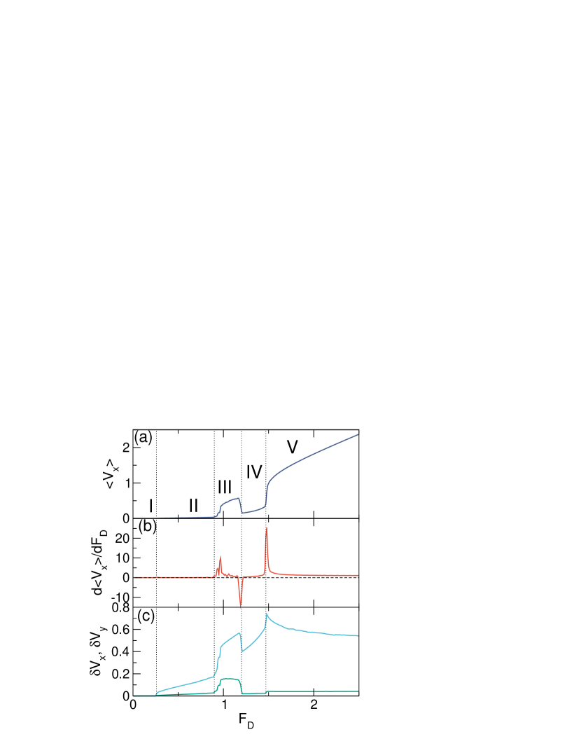
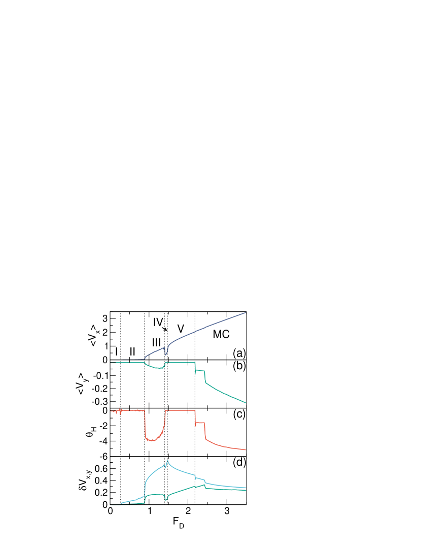
We first consider the zero intrinsic Hall angle situation with and . In Fig. 1(a,b) we plot and versus for a system with and , just above the first matching filling. We identify the same five distinct dynamical phases found previously Reichhardt18 ; Zhu01 ; Misko07 , consisting of a pinned phase I for , a sliding interstitial phase II where the small number of vortices that are not in the pinning sites move for , a disordered fluid flow phase III for , a soliton flow phase IV for , and a moving smectic phase V for . There is an upward spike in at the II-III boundary when a large number of vortices suddenly begin to move. The transition to phase IV where all the vortices are moving is accompanied by a sharp drop in the velocity, leading to a region of negative differential conductivity with . A peak in appears at the IV-V transition. In Fig. 1(c), the and versus curves provide a clearer signature of phase II followed by a large upward jump into phase III where the flow is more disordered. At the transition to phase IV, both and jump down when the motion becomes 1D again, while the IV-V transition is marked by a cusp in and a smaller jump in . We note that even though is zero for all drives in the overdamped limit, is always finite above the depinning transition. The difference between and reaches its largest value at the IV-V transition when a large number of pinned vortices coexist with a smaller number of vortices that are flowing along 1D channels. Within the moving smectic phase V, remains large since all of the vortices are moving but rows that are more highly occupied travel faster than the other rows, giving variability in the velocity that gradually diminishes with increasing drive. There is a small jump in at the IV-V transition due to a slight increase in the ability of the vortices to wiggle in the direction transverse to the drive once all the vortices have depinned. In previous work on a system of this type Reichhardt18 ; Zhu01 ; Misko07 , the curves were not measured since long simulation times are required in order to obtain well-averaged data that can be differentiated; additionally, neither nor were measured.
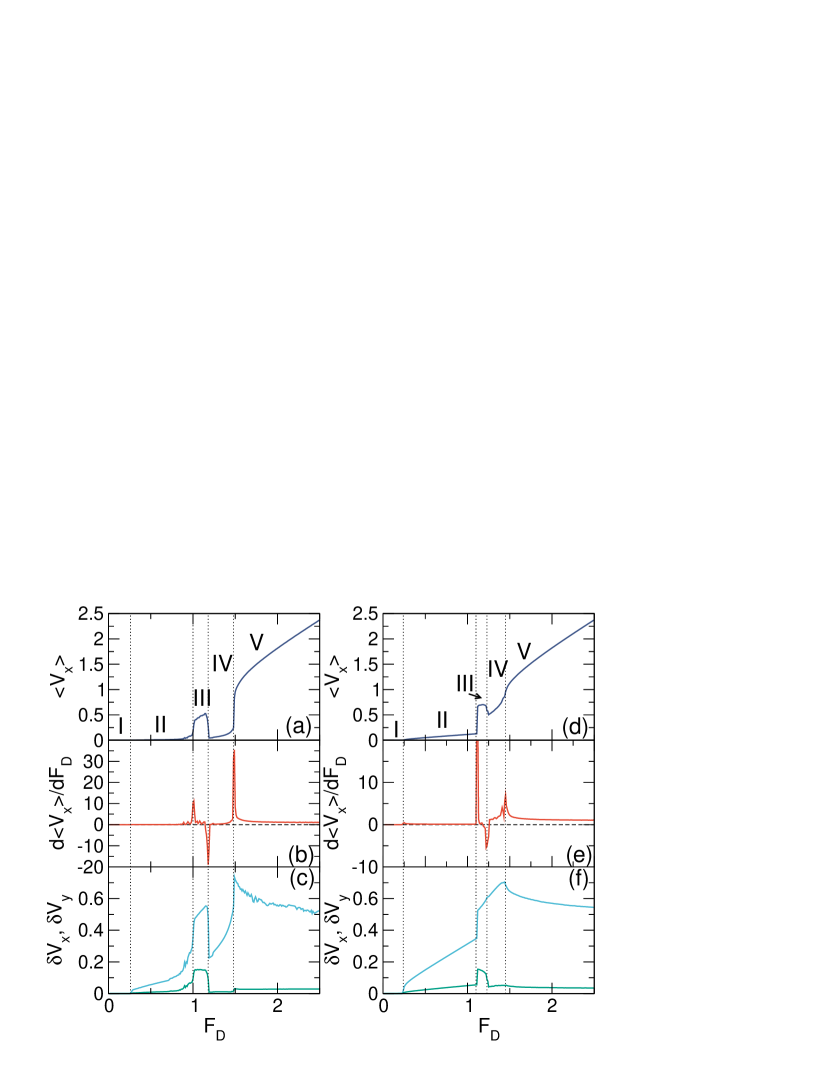
In Fig. 2(a,b,c) we show transport curves for the same system at a lower filling of where the number of interstitial vortices is smaller. The III-IV transition becomes even sharper, as indicated by and versus in Fig. 2(c). Even though the number of moving interstitial vortices is reduced, these vortices still create an instability among the pinned vortices that leads to the emergence of the liquid phase III, while in phase IV the motion is strictly 1D and the smaller number of interstitials are strongly localized in the form of incommensurations sliding along the rows of pinning sites. Figure 2(d,e,f) shows that the same phases occur at a higher filling of , but the downward jump in at the III-IV transition is reduced in size since a larger number of solitons are present in phase IV. At this filling, where the number of interstitial vortices is approximately 14% of the number of pinning sites, the soliton is no longer localized at a single vortex but consists of a group of approximately three moving vortices that are displaced from the pinning sites, while the total number of moving vortices in phase III is close to 50%. There is no drop in at the III-IV transition for this filling, but the drop in at the transition to phase IV persists. A cusp still appears in at the IV-V transition.
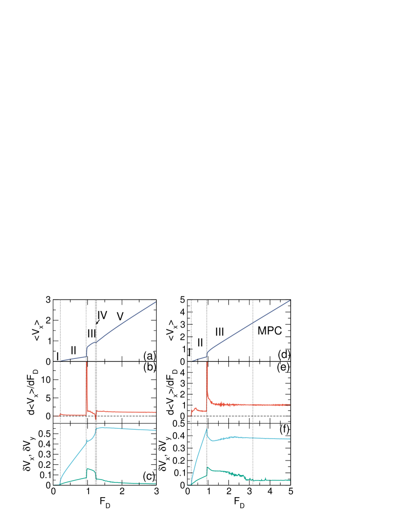
In Fig. 3(a,b,c), the transport curves for the same system at contain only a very small window of phase IV that appears as a small region of negative differential conductivity in Fig. 3(b). Since each soliton pulse involves about three vortices, for almost all of the vortices are moving in phase III, and there is no longer a dip in at the III-IV transition. The I-II, II-III, and IV-V transitions produce clear signatures in and .
At in Fig. 3(d,e,f), the transport curves indicate that phases IV and V are lost. There is still a pinned phase I and a transition to the interstitial flow phase II. Across the II-III transition, there are peaks in , , and ; however, there are now enough interstitial vortices present that confinement of the flow strictly along the pinning rows in phase IV is too energetically costly to occur, so phase III becomes greatly extended. When , the drive is large enough to overcome the effectiveness of the pinning, and the vortices partially reorder into a moving polycrystalline (MPC) state where some vortices move along the pinning rows while others do not. There is no signature of the III-MPC transition in or , but it does appear as a drop in .
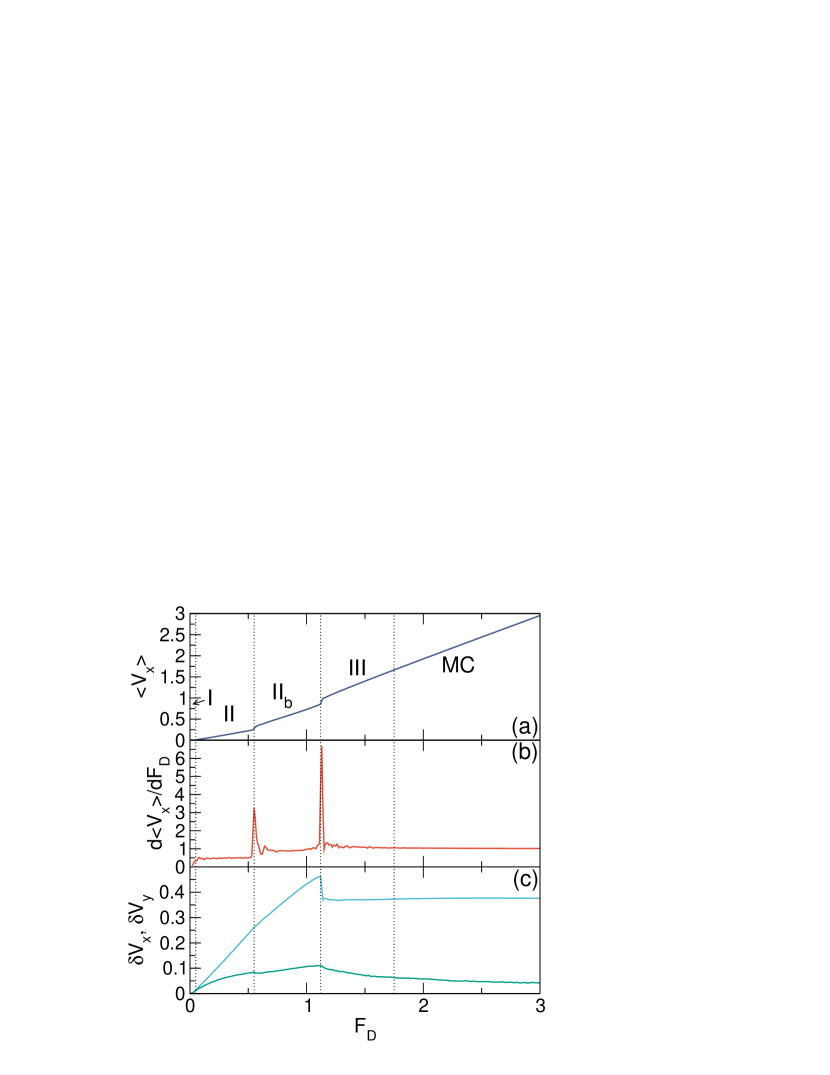
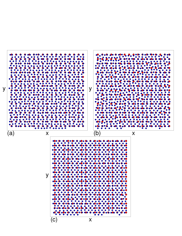
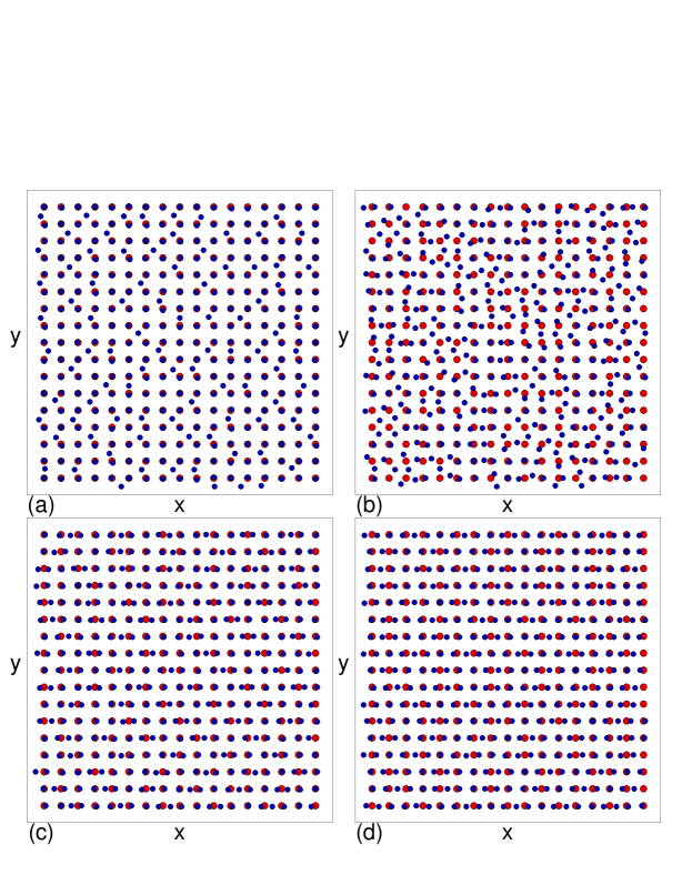
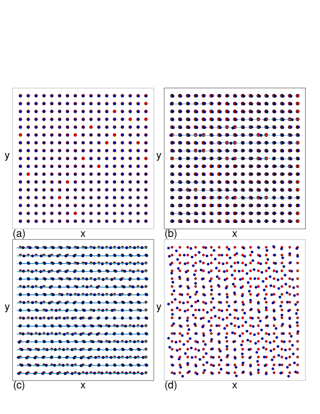
In Fig. 4(a) we illustrate the pinned phase I for the system in Fig. 3(a,b,c) with . Here all of the pinning sites are filled and the additional vortices sit in the interstitial regions. During phase II flow, these interstitial vortices move while the other vortices remain pinned, and the configuration looks like a translating version of Fig. 4(a). In phase III, shown in Fig. 4(b), the vortices are disordered and move in both the and directions, leading to the increase in both and found in Fig. 3(c). Figure 4(c) indicates that in phase IV, the vortices form a series of 1D channels with density modulations at the locations of the moving solitons. In phase V, illustrated in Fig. 4(d), all of the vortices are moving and there is smectic ordering. The vortex density along each 1D row is more uniform in phase V than in phase IV. Phase V occurs only for . For higher fillings, at higher drives the system can form a moving polycrystalline or crystalline phase.
For , the square checkerboard state that appears at contains interstitials. These interstitials depin first at a low depinning force and the system enters a state that we call phase IIa in which solitons flow through the interstitial lattice. For , there are enough interstitials present that all of the interstitials move simultaneously above the depinning threshold and adjacent rows of vortices sitting on the pinning sites slide with respect to each other to produce what we call phase IIb, which is a combination of phase II and phase IV.
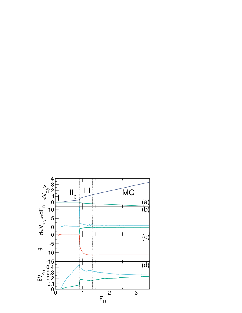
In Fig. 5 we show , , and versus for a system at . There are two prominent peaks in at the II-IIb and IIb-III transitions. In Fig. 6(a) we illustrate the vortex positions in phase IIb for the system in Fig. 5. Figure 6(b) shows the disordered flow in phase III, while in Fig. 6(c), in the moving crystal (MC) state, the vortices form a large scale crystal with a uniform orientation.
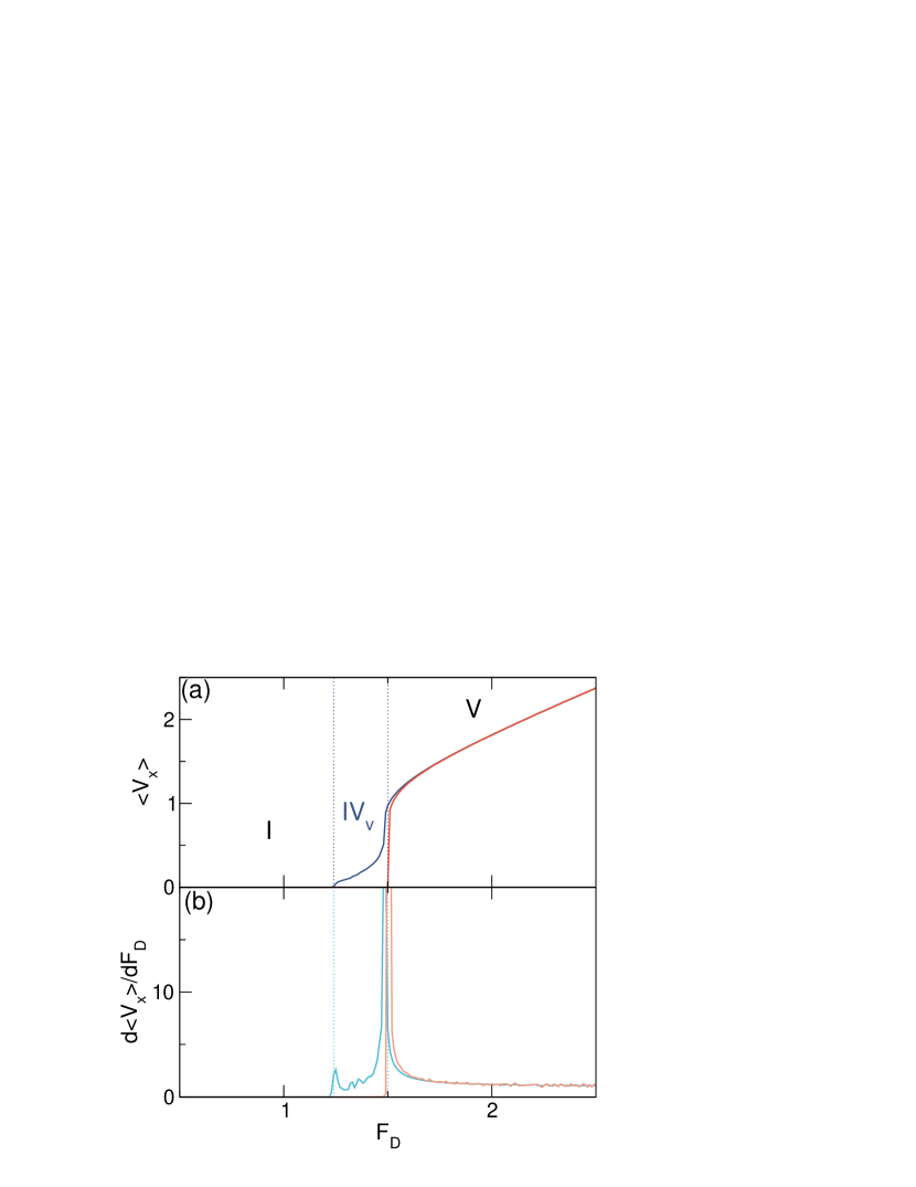
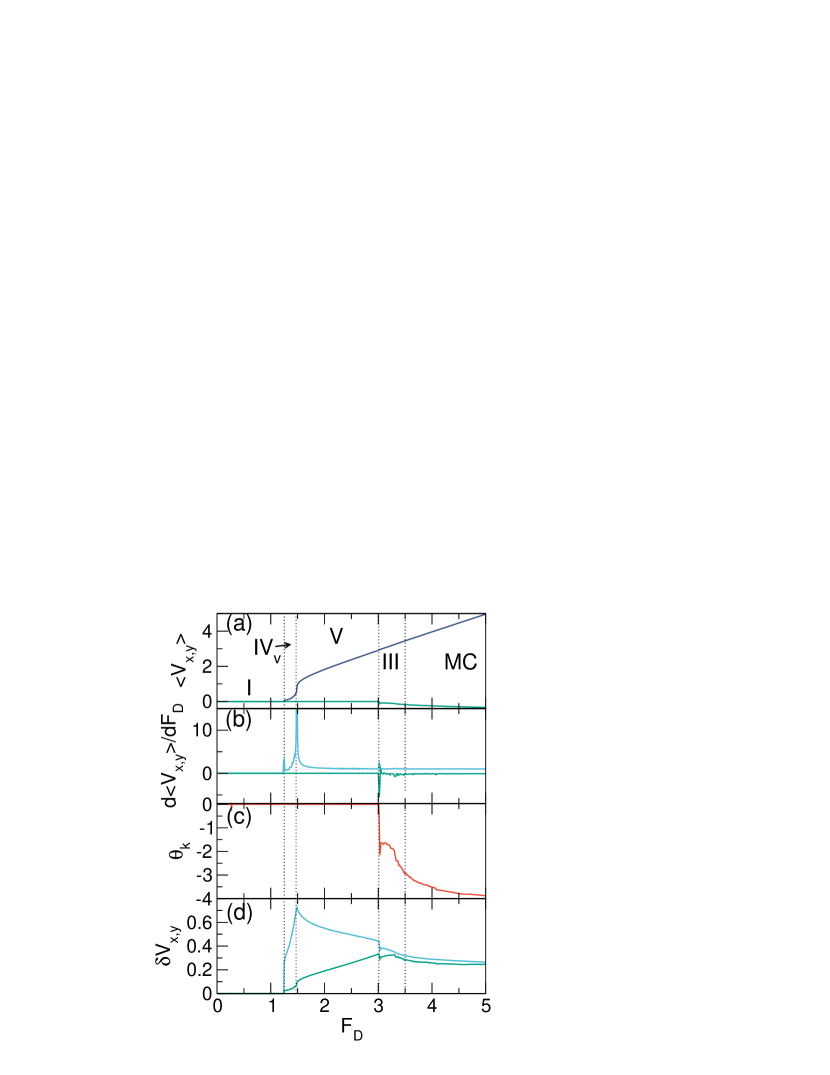
For , only three phases are present: the pinned phase, a moving vacancy or anti-kink phase termed IVv, and the moving smectic phase. In Fig. 7 we plot and for a system with . The ground state at this filling consists of a square lattice containing some vacancies. At , these vacancies depin first and the system enters phase IVv, which coincides with the first peak in the differential conductivity curve. The remaining vortices depin near , producing the second peak in the differential conductivity curve. Also appearing in the figure is the behavior for a sample with , where there is a single depinning transition from phase I directly into phase V at . A similar single depinning transition appears when the number of vacancies becomes very large for . At higher drives for , all of the vortices flow along the pinning rows and the behavior resembles phase V motion but with moving antikinks instead of moving kinks.
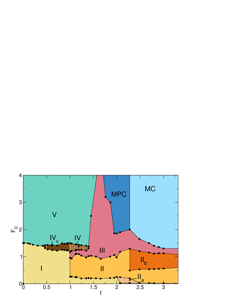
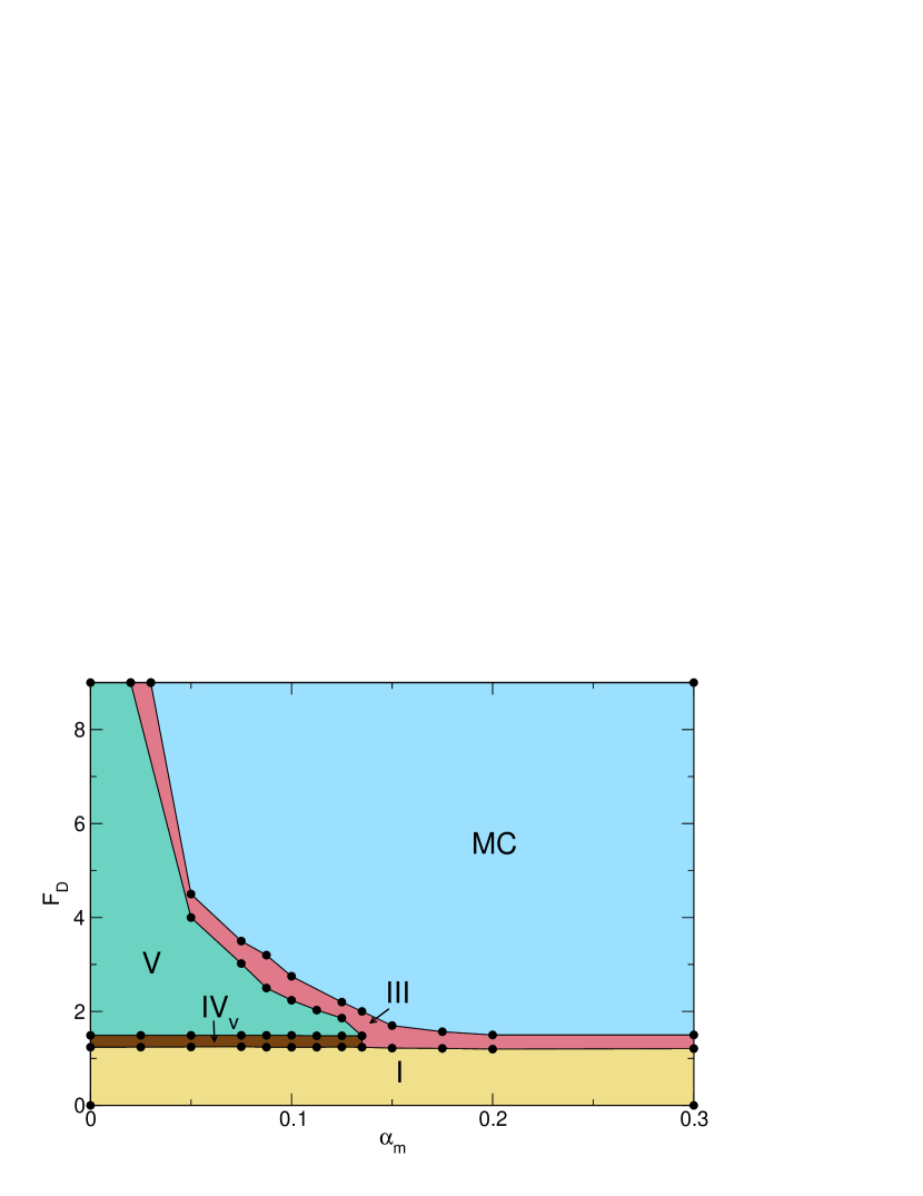
From the features in the velocity-force, , , and curves, we construct a diagram of the different phases, shown in Fig. 8, as a function of versus . The pinned phase I has a peak at and a larger peak precisely at . At these peaks, and at low , the system depins directly from phase I to phase V smectic flow. For , there is a two step depinning transition, with the system first depinning from phase I to the vacancy or antikink flow state in phase IVv, and then depinning into phase V at higher drives. For , the system depins from phase I into the interstitial flow phase II, followed by a transition associated with negative differential conductivity into the disordered flow phase III. At higher drives in this range of fillings, there is a transition to phase IV with soliton flow along the pinning rows, followed at high drives by phase V.
For in Fig. 8, the disordered phase III flow increases significantly in extent and extends up to very high drives. This is caused by a competition between the pinning energy, which favors having all of the vortices flow along the pinning rows as in phase IV, and the vortex-vortex interaction energy, since at these higher densities, the vortex density along a given pinning row would become prohibitively high if all of the vortices were accommodated along the pinning rows. What happens instead is that vortices along the pinning rows buckle and relieve the vortex-vortex interaction energy by ejecting some vortices into the interstitial region. These vortices then attempt to fall back into the pinning rows by ejecting other vortices, and the result is a highly disordered flow state. For , at high drives the vortices partially organize into the polycrystalline state described in Fig. 1, while for , an ordered moving crystal (MC) state can form. The MC emerges when the filling becomes high enough that the buckling of vortices out of the pinning rows produces rows of interstitial vortices that have roughly the same density as the rows of vortices moving along the pinning sites. This stabilizes the interstitial rows and puts a halt to the ejection process found at lower fillings.
For in Fig. 8, the initial depinning is followed by a small window of phase IIa in which only the solitons in the interstitial lattice move before the system enters the interstitial phsae II flow. For , a new phase emerges above phase II that we call phase IIb, where the interstitial vortices are flowing but there is also flow of some of the vortices along the pinning rows. The IIb flow is generally 1D in nature, and is followed by a transition to the disordered fluid phase III and then by a transition into a moving crystal at higher drives.
The phase diagram shown in Fig. 8 has several features that differ from the phase diagram obtained in earlier work Reichhardt98 due to the higher pinning density we consider here. Additionally, in Ref. Reichhardt98 , the phase diagram boundaries were determined using only the velocity-force curves, but here we add information from , , and to better characterize all of the phases. The biggest difference is that a large window of the disordered phase III appears around in Fig. 8, since the denser pinning brings vortices in the interstitial regions closer to the vortices flowing along the pinning rows and enhances the ejection process that leads to the disordered flow.
4 Finite Magnus Force
We next examine how these dynamic phases evolve when a finite Magnus force is introduced. We first consider a filling of , where there is a two step depinning in which vacancies move above the first depinning transition and the remaining vortices move above the second depinning transition. In Fig. 9(a) we plot and versus for a sample with and , where the intrinsic Hall angle is , and in Fig. 9(b) we show the corresponding and versus . The two step depinning transition persists, as indicated by the pair of peaks in at and . The transverse velocity up to , above which becomes finite and the particles start to move in the negative -direction. This transverse depinning transition is accompanied by a dip in . In Fig. 9(c) we plot the measured Hall angle , which has a jump to a finite value near . As increases, the magnitude of increases and approaches the intrinsic value at higher drives. The plots of and versus in Fig. 9(d) indicate that in phase IVv and phase V, , while above the cusp at , and have nearly the same value. Above the transverse depinning transition, when the particles begin to move in the direction, the flow is in the disordered phase III state, while at higher drives the particles organize into a moving crystal (MC) state. When the Magnus term is finite, the disordered flow phase III always has a finite Hall angle. Since the particles are moving at an angle, they do not lock to a symmetry direction of the substrate, and only form the moving crystal phase when the drive is high enough to cause the particles to float above the substrate.
In Fig. 10(a) we illustrate the particle and pinning site locations for the system in Fig. 9 at where there is a square ground state containing pinned vacancies. At in phase IVa, Fig. 10(b) shows the particle trajectories along with the particle and pinning site locations. Here the vacancies move opposite to the driving direction along 1D chains while the individual particles in those chains move in the driving direction one hop at a time, and the remaining particles are pinned. In Fig. 10(c), at in phase V, all of the particles are moving along the pinning rows and exhibit a smectic ordering. Figure 10(d) shows only the particle and pin locations without trajectories for the moving crystal phase at , where the particles form a triangular lattice that translates at an angle with respect to the pinning lattice.
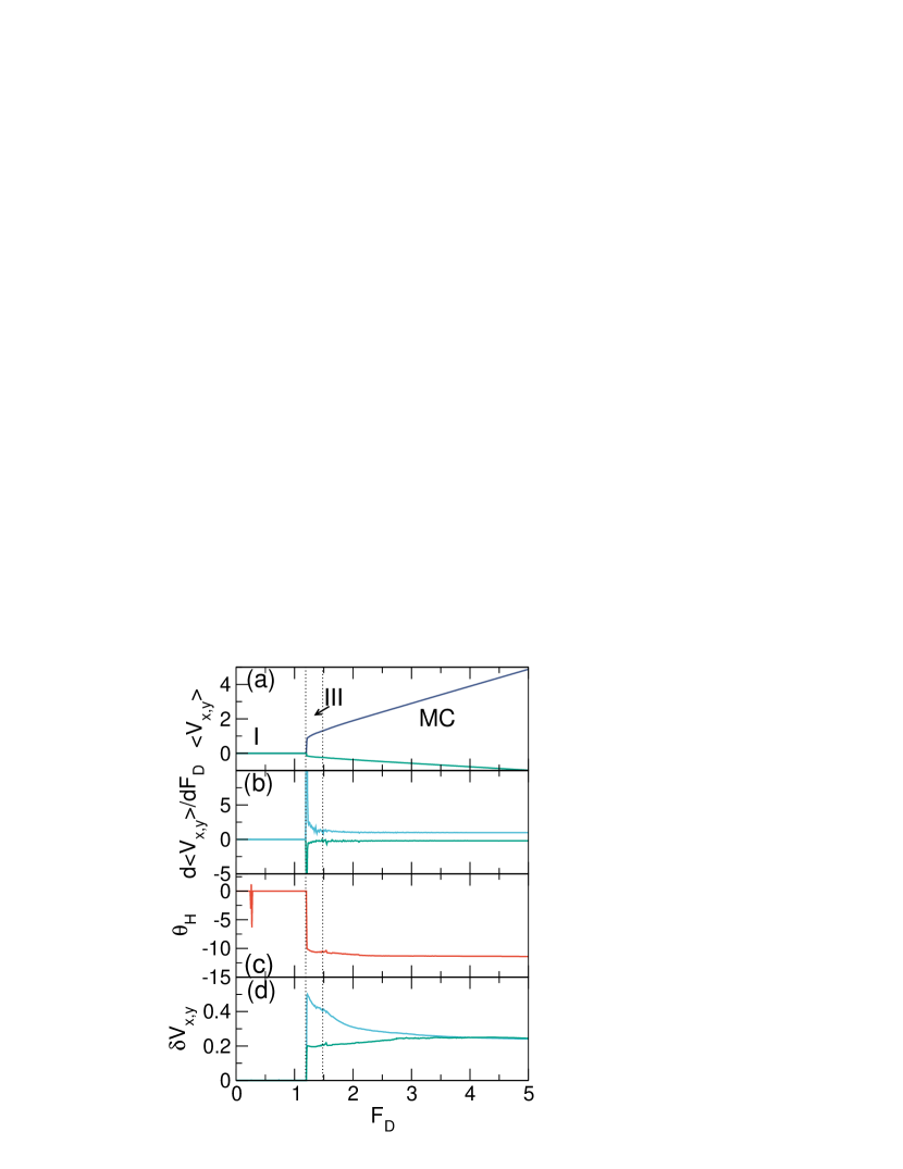
When increases, phases IVv and V are lost, as shown in Fig. 11 where we plot , , , , , and versus for a sample with , , and . Here there is a single peak in and a single dip in at the transition from the pinned phase I to the fluctuating liquid phase III, and rapidly approaches the intrinsic value just above the depinning transition. At higher drives, the fluctuations and parallel and transverse to the driving direction become nearly identical in magnitude.
From the features in the transport curves for , we can construct a dynamic phase diagram as a function of versus , as shown in Fig. 12. Here we find the pinned phase I, the disordered or fluid flow phase III, the 1D flow of vacancies in phase IVv, the smectic flow phase V, and the moving crystal phase MC. In this case, the depinning threshold is almost independent of . In some studies, the velocity above depinning decreases with increasing when the particle trajectories are bent around the pinning sites Nagaosa13 ; Reichhardt15a . Since can only modify the motion of a moving particle, if the particle has settled into a pinned state, the depinning threshold is insensitive to the value of . It may be possible that if the drive were increased more rapidly from zero, the depinning force could decrease with increasing , but we are working in the limit where the drive is incremented so slowly that the depinning threshold has no rate dependence. For , the system depins from phase I into phase IVv and then transitions into phase V. At higher drives, there is a window of phase III separating phase V from the moving crystal MC phase, which has a finite Hall angle. The III-MC transition roughly follows the line for . When , the system depins from phase I directly into phase III, which has a finite Hall angle. In some cases, particularly for smaller , we can observe some locking steps where the motion of the particles locks to one of the symmetry directions of the pinning lattice. Particularly strong directional locking occurs when , where is aligned with one of the major symmetry directions of the square pinning array. Our results also show that there is a range of Magnus terms over which the dynamical behavior of the system remains essentially the same as that of an overdamped system with .
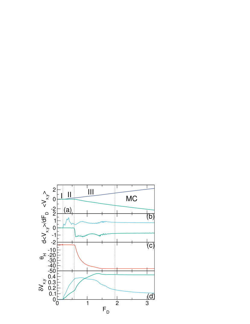
We next consider the impact of the Magnus term on the behavior for . In Fig. 13 we plot , , , , and versus for a system with at , , and . When the system depins from phase I into phase II, the interstitial particles move in the driving direction with a Hall angle of . In phase III, becomes finite and the magnitude of the Hall angle increases up to . The transition to phase IV is marked by a decrease of to zero and a drop in that produces negative differential conduction. This can be viewed as an example of reentrant transverse pinning. When , the system enters phase V, and near , a moving crystal state emerges that is marked by jumps in and to finite values. increases with increasing in phases II and III, dips during phase IV, and shows another drop at the transition to the MC phase, while shows a drop in phase IV and a jump up at the MC transition. There is a locking step with finite fixed at the beginning of the MC phase. For smaller values of , we observe the same trends, but the V-MC transition shifts to higher values of .
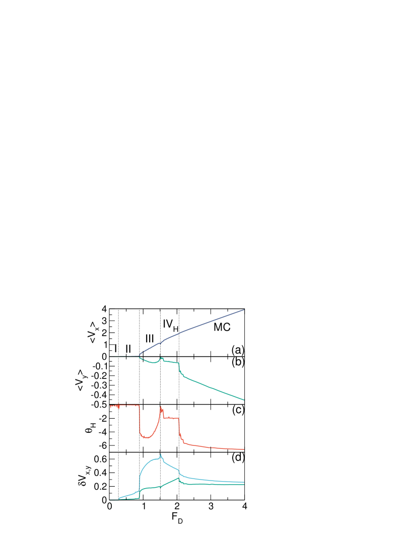
For , an inversion of the velocity-force curves occurs and the features found in for now appear in the curves instead. These include negative differential conductivity as well as an additional phase called IVH consisting of solitons flowing with a finite Hall angle. In Fig. 14 we show , , , and versus for a system with at , , and . We find a pinned phase I, an interstitial flow phase II with no Hall angle, and a disordered flow phase III with a Hall angle close to . There is a region of negative differential conductivity in near the III-IVH transition, and in phase IVH, there is soliton flow at a Hall angle of close to . At high drives, there is a jump in the magnitude of at the onset of the moving crystal phase MC. The III-IVH transition produces signatures in , , and . In the previously observed phase IV, the solitons are moving strictly along the direction with , whereas in phase IVH, each soliton moves primarily along the direction but makes periodic jumps in the direction, giving a finite Hall angle. As increases, the width of the IVH phase decreases until the system transitions directly from phase III to phase MC.
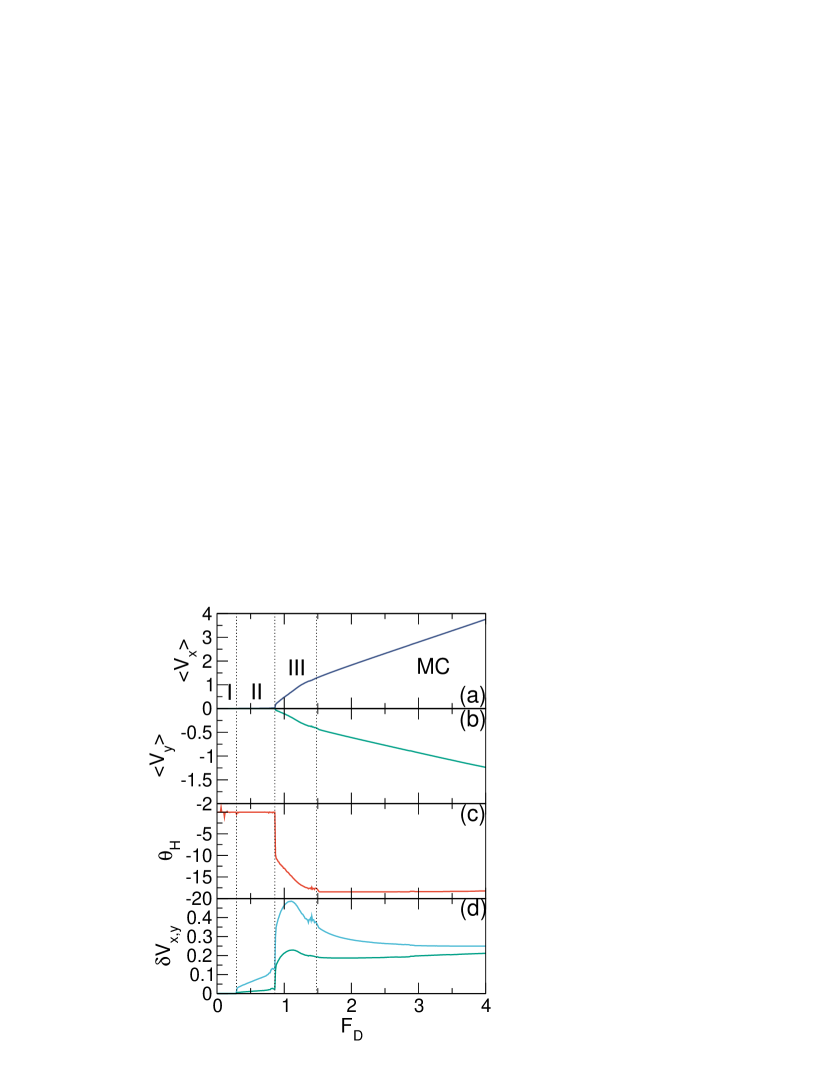
In Fig. 15 we plot , , , , and versus for a system with at , , and . We observe the pinned phase I, the interstitial phase II with zero Hall angle, the disordered flow phase III with a finite Hall angle that increases in magnitude with increasing , and a moving crystal with a Hall angle close to the intrinsic value. Phase IVH is now missing, and shows a peak near the III-MC transition.
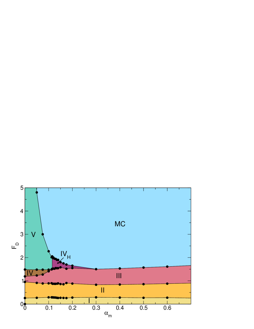
We use the features in the velocity-force, , , and curves to construct the dynamical phase diagram for as a function of versus , shown in Fig. 16. Phases I, II, and III are fairly insensitive to the value of , although the disordered flow phase III now has a finite Hall angle. The soliton flow phase IV and smectic flow phase V, both with zero Hall angle, vanish above . There is a window of phase IVH, or soliton flow with a finite Hall angle, separating phase III from the moving crystal MC phase with finite Hall angle for .
We have also considered the evolution of the different phases at higher fillings. In Fig. 17 we plot the transport curves for the system from Fig. 1 at with , , and . There is a region of phase IIb flow with motion in both the interstitial regions and along the pinning rows at zero Hall angle. This is followed by a transition to the disordered flow phase III and then to the moving crystal MC phase, both with a finite Hall angle, and both detected using peaks in , , , and .
In Fig. 18 we plot , , , , , , and versus for the same system in Fig. 17 but at , , and . In this case, at low drives we find phase I along with the interstitial flow phase II, which contains multiple peaks in . For , both and reach constant values, and locks to in the moving crystal phase.
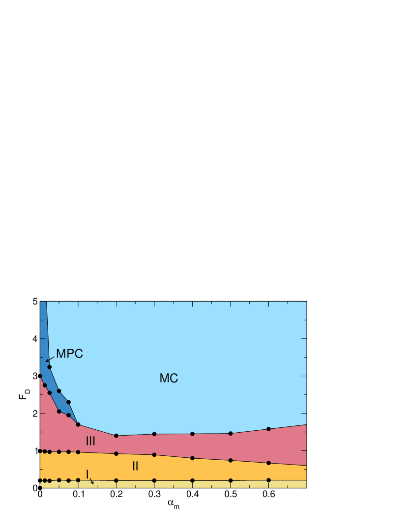
In Fig. 19 we show the dynamic phase diagram as a function of versus for the system in Figs. 17 and 18 at . The pinned phase I and interstitial flow phase II vary little as changes. The disordered flow phase III decreases in extent with increasing before saturating in width near . The moving polycrystalline phase MPC appears at higher drives only when , and is replaced by the moving crystal MC phase at higher .
5 Summary
We have investigated the dynamic phases of superconducting vortices and Magnus particles such as skyrmions interacting with a square periodic pinning array. For the superconducting vortex case where the Magnus force is zero and there is only a damping term, we map the different phases as a function of filling up to the second matching filling. Just above the first matching filling, pinned vortices coexist with a small number of interstitial vortices in the regions between the pinning sites, and as a function of drive, a series of phases appear including pinned, interstitial flow, disordered fluid flow, soliton flow, and smectic flow. At the transition from fluid to soliton flow, there is strong negative differential conductivity. We show that the differential conductivity curves and the variance in the velocity fluctuations provide complementary information to the previously considered velocity-force curves, and make it possible to identify several previously overlooked phases. For fillings just below the first matching filling, there is a flow of anti-kinks or solitons along with a double peak in the differential conductivity curves. When a small Magnus force is present, we find that these same phases can occur but that the fluid phases exhibit a finite Hall angle while the interstitial, soliton, and smectic phases do not. We also find a reentrant Hall effect in which the Hall angle is finite at lower drives in the fluid phase but drops back to zero at higher drives when the system enters a soliton flow state. For somewhat higher Magnus forces, we find that the transverse velocity-force curves exhibit the same features found in the longitudinal velocity-force curves at zero Magnus force. Specifically, regions of negative differential conductivity appear, and a new soliton phase emerges that has a finite Hall angle. We map out the different phases a function of filling and the Magnus force component. Our results should be relevant for superconducting systems in which the vortices have a finite Magnus term and for skyrmion systems in the regime of smaller skyrmion Hall effects. Additionally, our work indicates that kinks, antikinks, or interstitial flow of finite Magnus term particles such as skyrmions on 2D pinning arrays are associated with zero or reduced Hall angles, which could be useful for device creation.
Data availability
The datasets generated during and/or analyzed during
the current study are available from the corresponding
author upon reasonable request.
Acknowledgements This work was supported by the US Department of Energy through the Los Alamos National Laboratory and Research Foundation-Flanders (FWO). Los Alamos National Laboratory is operated by Triad National Security, LLC, for the National Nuclear Security Administration of the U. S. Department of Energy (Contract No. 892333218NCA000001).
Competing Interests
The authors declare no competing interests.
Author contributions
All authors contributed equally to this work.
References
- \bibcommenthead
- (1) Bak, P.: Commensurate phases, incommensurate phases and the devil’s staricase. Rep. Prog. Phys. 45(6), 587–629 (1982). https://doi.org/10.1088/0034-4885/45/6/001
- (2) Braun, O.M., Kivshar, Y.S.: Nonlinear dynamics of the Frenkel-Kontorova model. Phys. Rep. 306(1-2), 1–108 (1998). https://doi.org/10.1016/S0370-1573(98)00029-5
- (3) Reichhardt, C., Reichhardt, C.J.O.: Depinning and nonequilibrium dynamic phases of particle assemblies driven over random and ordered substrates: a review. Rep. Prog. Phys. 80(2), 026501 (2017). https://doi.org/%****␣manuscript.tex␣Line␣1450␣****10.1088/1361-6633/80/2/026501
- (4) Baert, M., Metlushko, V.V., Jonckheere, R., Moshchalkov, V.V., Bruynseraede, Y.: Composite flux-line lattices stabilized in superconducting films by a regular array of artificial defects. Phys. Rev. Lett. 74, 3269–3272 (1995). https://doi.org/10.1103/PhysRevLett.74.3269
- (5) Harada, K., Kamimura, O., Kasai, H., Matsuda, T., Tonomura, A., Moshchalkov, V.V.: Direct observation of vortex dynamics in superconducting films with regular arrays of defects. Science 274(5290), 1167–1170 (1996). https://doi.org/10.1126/science.274.5290.1167
- (6) Reichhardt, C., Olson, C.J., Nori, F.: Nonequilibrium dynamic phases and plastic flow of driven vortex lattices in superconductors with periodic arrays of pinning sites. Phys. Rev. B 58, 6534–6564 (1998). https://doi.org/10.1103/PhysRevB.58.6534
- (7) Brunner, M., Bechinger, C.: Phase behavior of colloidal molecular crystals on triangular light lattices. Phys. Rev. Lett. 88, 248302 (2002). https://doi.org/10.1103/PhysRevLett.88.248302
- (8) Berdiyorov, G.R., Milošević, M.V., Peeters, F.M.: Novel commensurability effects in superconducting films with antidot arrays. Phys. Rev. Lett. 96, 207001 (2006). https://doi.org/10.1103/PhysRevLett.96.207001
- (9) Brazda, T., Silva, A., Manini, N., Vanossi, A., Guerra, R., Tosatti, E., Bechinger, C.: Experimental observation of the Aubry transition in two-dimensional colloidal monolayers. Phys. Rev. X 8, 011050 (2018). https://doi.org/10.1103/PhysRevX.8.011050
- (10) Reichhardt, C., Olson, C.J., Nori, F.: Dynamic phases of vortices in superconductors with periodic pinning. Phys. Rev. Lett. 78, 2648–2651 (1997). https://doi.org/10.1103/PhysRevLett.78.2648
- (11) Bohlein, T., Mikhael, J., Bechinger, C.: Observation of kinks and antikinks in colloidal monolayers driven across ordered surfaces. Nature Mater. 11(2), 126–130 (2012). https://doi.org/10.1038/NMAT3204
- (12) Vanossi, A., Manini, N., Tosatti, E.: Static and dynamic friction in sliding colloidal monolayers. Proc. Natl. Acad. Sci. (USA) 109(41), 16429–16433 (2012). https://doi.org/%****␣manuscript.tex␣Line␣1600␣****10.1073/pnas.1213930109
- (13) Vanossi, A., Manini, N., Urbakh, M., Zapperi, S., Tosatti, E.: Colloquium: Modeling friction: From nanoscale to mesoscale. Rev. Mod. Phys. 85, 529–552 (2013). https://doi.org/10.1103/RevModPhys.85.529
- (14) Hasnain, J., Jungblut, S., Dellago, C.: Dynamic phases of colloidal monolayers sliding on commensurate substrates. Soft Matter 9(25), 5867–5873 (2013). https://doi.org/10.1039/c3sm50458a
- (15) Martín, J.I., Vélez, M., Nogués, J., Schuller, I.K.: Flux pinning in a superconductor by an array of submicrometer magnetic dots. Phys. Rev. Lett. 79, 1929–1932 (1997). https://doi.org/%****␣manuscript.tex␣Line␣1650␣****10.1103/PhysRevLett.79.1929
- (16) Mangold, K., Leiderer, P., Bechinger, C.: Phase transitions of colloidal monolayers in periodic pinning arrays. Phys. Rev. Lett. 90, 158302 (2003). https://doi.org/10.1103/PhysRevLett.90.158302
- (17) Reichhardt, C., Ray, D., Reichhardt, C.J.O.: Quantized transport for a skyrmion moving on a two-dimensional periodic substrate. Phys. Rev. B 91, 104426 (2015). https://doi.org/10.1103/PhysRevB.91.104426
- (18) Saha, S., Zelent, M., Finizio, S., Mruczkiewicz, M., Tacchi, S., Suszka, A.K., Wintz, S., Bingham, N.S., Raabe, J., Krawczyk, M., Heyderman, L.J.: Formation of Néel-type skyrmions in an antidot lattice with perpendicular magnetic anisotropy. Phys. Rev. B 100, 144435 (2019). https://doi.org/10.1103/PhysRevB.100.144435
- (19) Gutierrez, J., Silhanek, A.V., Van de Vondel, J., Gillijns, W., Moshchalkov, V.V.: Transition from turbulent to nearly laminar vortex flow in superconductors with periodic pinning. Phys. Rev. B 80, 140514 (2009). https://doi.org/10.1103/PhysRevB.80.140514
- (20) Avci, S., Xiao, Z.L., Hua, J., Imre, A., Divan, R., Pearson, J., Welp, U., Kwok, W.K., Crabtree, G.W.: Matching effect and dynamic phases of vortex matter in Bi2Sr2CaCu2O8 nanoribbon with a periodic array of holes. Appl. Phys. Lett. 97(4), 042511 (2010). https://doi.org/10.1063/1.3473783
- (21) Zhu, B.Y., Van Look, L., Moshchalkov, V.V., Zhao, B.R., Zhao, Z.X.: Vortex dynamics in regular arrays of asymmetric pinning centers. Phys. Rev. B 64, 012504 (2001). https://doi.org/10.1103/PhysRevB.64.012504
- (22) Misko, V.R., Savel’ev, S., Rakhmanov, A.L., Nori, F.: Negative differential resistivity in superconductors with periodic arrays of pinning sites. Phys. Rev. B 75, 024509 (2007). https://doi.org/10.1103/PhysRevB.75.024509
- (23) da Silva, R.M., de Souza Silva, C.C.: Vortex density waves and negative absolute resistance in patterned superconductors. Phys. Rev. B 83, 184514 (2011). https://doi.org/10.1103/PhysRevB.83.184514
- (24) Van Look, L., Rosseel, E., Van Bael, M.J., Temst, K., Moshchalkov, V.V., Bruynseraede, Y.: Shapiro steps in a superconducting film with an antidot lattice. Phys. Rev. B 60, 6998–7000 (1999). https://doi.org/10.1103/PhysRevB.60.R6998
- (25) Reichhardt, C., Zimányi, G.T., Grønbech-Jensen, N.: Complex dynamical flow phases and pinning in superconductors with rectangular pinning arrays. Phys. Rev. B 64, 014501 (2001). https://doi.org/10.1103/PhysRevB.64.014501
- (26) Reichhardt, C., Reichhardt, C.J.O.: Spontaneous transverse response and amplified switching in superconductors with honeycomb pinning arrays. Phys. Rev. Lett. 100, 167002 (2008). https://doi.org/10.1103/PhysRevLett.100.167002
- (27) Chen, Q.H., Carballeira, C., Nishio, T., Zhu, B.Y., Moshchalkov, V.V.: Stress overshoot and configuration-induced hysteresis in type-II superconducting films with a periodic pinning array. Phys. Rev. B 78, 172507 (2008). https://doi.org/10.1103/PhysRevB.78.172507
- (28) Pogosov, W.V., Zhao, H.J., Misko, V.R., Peeters, F.M.: Kink-antikink vortex transfer in periodic-plus-random pinning potential: Theoretical analysis and numerical experiments. Phys. Rev. B 81, 024513 (2010). https://doi.org/10.1103/PhysRevB.81.024513
- (29) Yetis, H.: Static and dynamic behaviours of multivortex states in a superconducting sample with mesoscopic pinning sites. Eur. Phys. J. B 83(1), 93–105 (2011). https://doi.org/10.1140/epjb/e2011-20290-y
- (30) Facio, J.I., Abate, A., Guimpel, J., Cornaglia, P.S.: Vortex kinks in superconducting films with periodically modulated thickness. J. Phys.: Condens. Matter 25, 245701 (2013). https://doi.org/10.1088/0953-8984/25/24/245701
- (31) Chen, Q.H., Shi, D.Q., Li, W.X., Zhu, B.Y., Moshchalkov, V.V., Dou, S.X.: Configuration-induced vortex motion in type-II superconducting films with periodic magnetic dot arrays. Supercond. Sci. Technol. 27, 065004 (2014). https://doi.org/10.1088/0953-2048/27/6/065004
- (32) Verga, L.G., Vizarim, N.P., Carlone, M., Venegas, P.A.: Vortex dynamic phases in type II superconducting strips with regular and flattened triangular pinning arrays. J. Supercond. Novel Mag. 32, 1179 (2019). https://doi.org/10.1007/s10948-018-4821-6
- (33) Ao, P., Thouless, D.J.: Berry’s phase and the Magnus force for a vortex line in a superconductor. Phys. Rev. Lett. 70, 2158–2161 (1993). https://doi.org/10.1103/PhysRevLett.70.2158
- (34) Sonin, E.B.: Magnus force in superfluids and superconductors. Phys. Rev. B 55, 485–501 (1997). https://doi.org/10.1103/PhysRevB.55.485
- (35) Dorsey, A.T.: Vortex motion and the Hall effect in type-II superconductors: A time-dependent Ginzburg-Landau theory approach. Phys. Rev. B 46, 8376–8392 (1992). https://doi.org/10.1103/PhysRevB.46.8376
- (36) Lefebvre, J., Hilke, M., Gagnon, R., Altounian, Z.: Transverse vortex dynamics in superconductors. Phys. Rev. B 74, 174509 (2006). https://doi.org/10.1103/PhysRevB.74.174509
- (37) Ogawa, R., Nabeshima, F., Nishizaki, T., Maeda, A.: Large Hall angle of vortex motion in high- cuprate superconductors revealed by microwave flux-flow Hall effect. Phys. Rev. B 104, 020503 (2021). https://doi.org/10.1103/PhysRevB.104.L020503
- (38) Wlazłowski, G., Sekizawa, K., Magierski, P., Bulgac, A., Forbes, M.M.: Vortex pinning and dynamics in the neutron star crust. Phys. Rev. Lett. 117, 232701 (2016). https://doi.org/10.1103/PhysRevLett.117.232701
- (39) Tung, S., Schweikhard, V., Cornell, E.A.: Observation of vortex pinning in Bose-Einstein condensates. Phys. Rev. Lett. 97, 240402 (2006). https://doi.org/10.1103/PhysRevLett.97.240402
- (40) Kasamatsu, K., Tsubota, M.: Dynamical vortex phases in a Bose-Einstein condensate driven by a rotating optical lattice. Phys. Rev. Lett. 97, 240404 (2006). https://doi.org/10.1103/PhysRevLett.97.240404
- (41) Reichhardt, C., Reichhardt, C.J.O.: Dynamics of Magnus-dominated particle clusters, collisions, pinning, and ratchets. Phys. Rev. E 101, 062602 (2020). https://doi.org/10.1103/PhysRevE.101.062602
- (42) Banerjee, D., Souslov, A., Abanov, A.G., Vitelli, V.: Odd viscosity in chiral active fluids. Nature Commun. 8, 1573 (2017). https://doi.org/10.1038/s41467-017-01378-7
- (43) Bililign, E.S., Usabiaga, F.B., Ganan, Y.A., Poncet, A., Soni, V., Magkiriadou, S., Shelley, M.J., Bartolo, D., Irvine, W.T.M.: Motile dislocations knead odd crystals into whorls. Nature Phys. 18, 212 (2022). https://doi.org/10.1038/s41567-021-01429-3
- (44) Yu, X.Z., Onose, Y., Kanazawa, N., Park, J.H., Han, J.H., Matsui, Y., Nagaosa, N., Tokura, Y.: Real-space observation of a two-dimensional skyrmion crystal. Nature (London) 465(7300), 901–904 (2010). https://doi.org/10.1038/nature09124
- (45) Nagaosa, N., Tokura, Y.: Topological properties and dynamics of magnetic skyrmions. Nature Nanotechnol. 8(12), 899–911 (2013). https://doi.org/10.1038/NNANO.2013.243
- (46) Mühlbauer, S., Binz, B., Jonietz, F., Pfleiderer, C., Rosch, A., Neubauer, A., Georgii, R., Böni, P.: Skyrmion lattice in a chiral magnet. Science 323(5916), 915–919 (2009). https://doi.org/10.1126/science.1166767
- (47) Everschor-Sitte, K., Sitte, M.: Real-space Berry phases: Skyrmion soccer (invited). J. Appl. Phys. 115(17), 172602 (2014). https://doi.org/10.1063/1.4870695
- (48) Jiang, W., Zhang, X., Yu, G., Zhang, W., Wang, X., Jungfleisch, M.B., Pearson, J.E., Cheng, X., Heinonen, O., Wang, K.L., Zhou, Y., Hoffmann, A., te Velthuis, S.G.E.: Direct observation of the skyrmion Hall effect. Nature Phys. 13(2), 162–169 (2017). https://doi.org/10.1038/NPHYS3883
- (49) Litzius, K., Lemesh, I., Krüger, B., Bassirian, P., Caretta, L., Richter, K., Büttner, F., Sato, K., Tretiakov, O.A., Förster, J., Reeve, R.M., Weigand, M., Bykova, I., Stoll, H., Schütz, G., Beach, G.S.D., Kläui, M.: Skyrmion Hall effect revealed by direct time-resolved X-ray microscopy. Nature Phys. 13(2), 170–175 (2017). https://doi.org/10.1038/NPHYS4000
- (50) Woo, S., Song, K.M., Zhang, X., Zhou, Y., Ezawa, M., Liu, X., Finizio, S., Raabe, J., Lee, N.J., Kim, S., Park, S.-Y., Kim, Y., Kim, J.-Y., Lee, D., Lee, O., Choi, J.W., Min, B.-C., Koo, H.C., Chang, J.: Current-driven dynamics and inhibition of the skyrmion Hall effect of ferrimagnetic skyrmions in GdFeCo films. Nature Commun. 9, 959 (2018). https://doi.org/10.1038/s41467-018-03378-7
- (51) Reichhardt, C., Reichhardt, C.J.O.: Plastic flow and the skyrmion hall effect. Nature Commun. 11, 738 (2020). https://doi.org/10.1038/s41467-020-14587-4
- (52) Zeissler, K., Finizio, S., Barton, C., Huxtable, A.J., Massey, J., Raabe, J., Sadovnikov, A.V., Nikitov, S.A., Brearton, R., Hesjedal, T., van der Laan, G., Rosamond, M.C., Linfield, E.H., Burnell, G., Marrows, C.H.: Diameter-independent skyrmion Hall angle observed in chiral magnetic multilayers. Nature Commun. 11(1), 428 (2020). https://doi.org/10.1038/s41467-019-14232-9
- (53) Reichhardt, C., Ray, D., Reichhardt, C.J.O.: Collective transport properties of driven skyrmions with random disorder. Phys. Rev. Lett. 114, 217202 (2015). https://doi.org/10.1103/PhysRevLett.114.217202
- (54) Kim, J.-V., Yoo, M.-W.: Current-driven skyrmion dynamics in disordered films. Appl. Phys. Lett. 110(13), 132404 (2017). https://doi.org/10.1063/1.4979316
- (55) Legrand, W., Maccariello, D., Reyren, N., Garcia, K., Moutafis, C., Moreau-Luchaire, C., Coffin, S., Bouzehouane, K., Cros, V., Fert, A.: Room-temperature current-induced generation and motion of sub-100 nm skyrmions. Nano Lett. 17(4), 2703–2712 (2017). https://doi.org/10.1021/acs.nanolett.7b00649
- (56) Juge, R., Je, S.-G., Chaves, D.d.S., Buda-Prejbeanu, L.D., Peña-Garcia, J., Nath, J., Miron, I.M., Rana, K.G., Aballe, L., Foerster, M., Genuzio, F., Menteş, T.O., Locatelli, A., Maccherozzi, F., Dhesi, S.S., Belmeguenai, M., Roussigné, Y., Auffret, S., Pizzini, S., Gaudin, G., Vogel, J., Boulle, O.: Current-driven skyrmion dynamics and drive-dependent skyrmion Hall effect in an ultrathin film. Phys. Rev. Applied 12, 044007 (2019). https://doi.org/10.1103/PhysRevApplied.12.044007
- (57) Reichhardt, C., Ray, D., Reichhardt, C.J.O.: Nonequilibrium phases and segregation for skyrmions on periodic pinning arrays. Phys. Rev. B 98, 134418 (2018). https://doi.org/10.1103/PhysRevB.98.134418
- (58) Feilhauer, J., Saha, S., Tobik, J., Zelent, M., Heyderman, L.J., Mruczkiewicz, M.: Controlled motion of skyrmions in a magnetic antidot lattice. Phys. Rev. B 102, 184425 (2020). https://doi.org/10.1103/PhysRevB.102.184425
- (59) Juge, R., Bairagi, K., Rana, K.G., Vogel, J., Sall, M., Mailly, D., Pham, V.T., Zhang, Q., Sisodia, N., Foerster, M., Aballe, L., Belmeguenai, M., Roussigné, Y., Auffret, S., Buda-Prejbeanu, L.D., Gaudin, G., Ravelosona, D., Boulle, O.: Helium ions put magnetic skyrmions on the track. Nano Lett. 21, 2989–2996 (2021). https://doi.org/10.1021/acs.nanolett.1c00136
- (60) Kern, L.-M., Pfau, B., Deinhart, V., Schneider, M., Klose, C., Gerlinger, K., Wittrock, S., Engel, D., Will, I., Günther, C.M., Liefferink, R., Mentink, J.H., Wintz, S., Weigand, M., Huang, M.-J., Battistelli, R., Metternich, D., Büttner, F., Höflich, K., Eisebitt, S.: Deterministic generation and guided motion of magnetic skyrmions by focused He+-ion irradiation. arXiv e-prints, 2022–12057
- (61) McDermott, D., Amelang, J., Reichhardt, C.J.O., Reichhardt, C.: Dynamic regimes for driven colloidal particles on a periodic substrate at commensurate and incommensurate fillings. Phys. Rev. E 88, 062301 (2013). https://doi.org/10.1103/PhysRevE.88.062301
- (62) Lin, S.-Z., Reichhardt, C., Batista, C.D., Saxena, A.: Particle model for skyrmions in metallic chiral magnets: Dynamics, pinning, and creep. Phys. Rev. B 87, 214419 (2013). https://doi.org/10.1103/PhysRevB.87.214419