Achieving Dexterous Bidirectional Interaction in Uncertain Conditions for Medical Robotics
Abstract
Medical robotics can help improve and extend the reach of healthcare services. A major challenge for medical robots is the complex physical interaction between the robot and the patients which is required to be safe. This work presents the preliminary evaluation of a recently introduced control architecture based on the Fractal Impedance Control (FIC) in medical applications. The deployed FIC architecture is robust to delay between the master and the replica robots. It can switch online between an admittance and impedance behaviour, and it is robust to interaction with unstructured environments. Our experiments analyse three scenarios: teleoperated surgery, rehabilitation, and remote ultrasound scan. The experiments did not require any adjustment of the robot tuning, which is essential in medical applications where the operators do not have an engineering background required to tune the controller. Our results show that is possible to teleoperate the robot to cut using a scalpel, do an ultrasound scan, and perform remote occupational therapy. However, our experiments also highlighted the need for a better robots embodiment to precisely control the system in 3D dynamic tasks.
Index Terms:
Medical Robotics, Teleoperation, Interaction ControlI Introduction
Robot-mediated medical services have been identified as a possible solution to the ageing population in developed countries in the last few decades. An older population implies a lower active workforce and an increase in age-related diseases, increasing strain on the healthcare sector [1, 2, 3, 4, 5, 6]. Additionally, as highlighted from the COVID-19 pandemic, reduced access to healthcare facilities can currently compromise healthcare quality. This problem was known in the sector, but it was not prioritised and was seen as a long term problem because it affected only the population living in remote locations. The pandemic has revealed the short term relevance of new technologies that can enhance the territorial permeability of these services.
Rehabilitation and robot-aided surgery were among the first applications in medical robotics[7, 1]. The rehabilitation robots have shown how the introduction of these technologies in the rehabilitation centre has allowed an increase of bandwidth and therapeutic improvements in the patients. Currently, there are multiple planar robots for upper-limb rehabilitation available on the market, which can also be deployed at home or community centres [6]. Concurrently, the knowledge gained for rehabilitation robots supported the development of assistive technologies for medical, civil, and industrial applications. These technologies aim to support pathological cases, but they also target the reduction of injuries in the healthy population [8].
Surgical robots were the other devices that immediately attracted the attention of researchers, which has been seen as an opportunity to allow doctors to operate on patients remotely [2, 5]. The endoscopic surgery also provided an ideal case study for robotics. Endoscopes were already an established device, which provided minimally invasive access to internal organs, and they had established protocols and techniques [9, 10]. Therefore, medical robots could be developed to automate and improve an available technology, which has also increased the acceptability of these technologies in the medical community. An additional benefit of endoscopic surgery is the quasi-spherical operational field that can be projected on a flat-screen without significantly impacting the operator perception. More recently, the knowledge gained from the development of co-bots, mentioned in the previous paragraph, has enabled the development of robots for orthopaedics surgery [11]. In these systems, the doctor interacts with the end-effector to increase the quality of knee and hip prosthetics; however, the literature on these systems does not indicate a significant benefit of robot-aided surgery compared to traditional systems [12].
Researchers have recently looked into performing other types of medical interventions in teleoperation, exploiting needles and scalpels[2, 5]. However, the intrinsic interaction complexity connected with the variegated mechanical properties of biological tissues poses a challenge to traditional interaction control approaches, which rely on contact models. These controllers also require extensive tuning for switching between operations, which requires both application-specific knowledge and profound knowledge of the control architecture. Furthermore, the introduction of delays and the exponential increase of computational complexity when multi-arms are involved render extremely challenging the applicability of these methods in teleoperation [5, 13]. Therefore, these method can potentially generate unsafe interaction due to the intrinsic energy tracking limitations due the discrete nature of the virtual tank conservative energy [14].
Other applications of co-bots in robotics involved automated diagnostics (e.g., ultrasound scan) and robot-aided TMS (Transcranial Magnetic Stimulation) [15, 16]. The automation of diagnostic technology looks into the possibility of completely automating examinations such as the ultrasound scan, looking into machine learning and neural network to identify anomalies in the image and perform a diagnosis. The application for TMS aims to improve the stimulation by improving the neural circuit targeting, being this technology’s effectiveness depends on the selective stimulation of the nervous tissues using magnetic induction.
Recently, our group has developed an impedance controller, called Fractal Impedance Controller (FIC), capable of robust interaction in unstructured environments without compromising the tracking accuracy [14, 17]. The FIC achieves these properties thanks to its passivity and path independent observer, making it robust to delays and reducing bandwidth in state feedback [18]. The passivity also allows multiple controllers to be superimposed without affecting their stability, enabling decoupling the control problems and reducing the computational complexity[19]. Earlier teleoperation experiments showcase how the proposed architecture enables the remote operator to collaborate with another person interacting with the replica robots[18, 20, 21, 22].
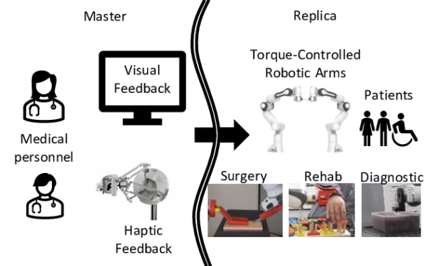
This manuscript presents the preliminary evaluation of the performances of teleoperation architecture based on the FIC in using a scalpel, performing occupational therapy and an ultrasound scan (Fig. 1). The scope is to understand the potential capabilities of the proposed method and identify the challenges to overcome. Section II gives a background on the FIC and describes the used architectures. Section III describes the experiments and presents the results. Sections IV and V discuss experimental results, and draw the conclusion, respectively.
II Control Architecture
The proposed architecture is composed of two sides with independent stability for their controllers, setting our control aside from other architectures requiring their controllers’ stability to be coupled. The master interfaces with the users (i.e., medical personnel) by measuring the motion of the operator, and it provides back haptic and visual feedback from the replica side (Fig. 1). The replica reproduces the operator’s movements and interacts with the patients and environment. This controller can operate one or multiple arms across a variety of tasks by changing the end-effector mounted on the robots, as it is shown on the right side of Fig. 1. It is worth noting that the arms can be either controlled independently or synchronised; notwithstanding the control modality, the stability of the two arms is independent, and their movements are synchronised, giving coordinated states for both effort and trajectory.
II-A Master Controller
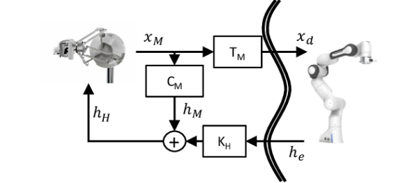
The master controller has three elements as described in Fig. 2. generate the desired pose for the replica depending on the selected control mode. We implemented the position and the velocity modes. The position mode passes the pose error of the master to the controllers of the replica device, reproducing it at the end-effector. It allows better dexterity in controlling the robot, limiting the workspace. The velocity mode updates the reference pose of the replica device based on the velocity recorded at the master end-effector. The equation of the two modes are:
| (1) |
where is the desired replica pose, is the initial pose of the robot when the position mode is selected, is the twist of the master device, and is the controller time step. It is worth noting that this is a simplified notation, as the integration of orientation in uses the exponential map from the Lie algebra theory [23].
is the virtual haptic feedback provided via the FIC-based controller NLPD, described in the appendix. Its function is to provide additional haptic information beyond the interaction force recorded on the replica end-effector. For example, we have used it to provide feedback when the limits of the replica workspace is reached when the master command is in position mode. The two haptic feedbacks are combined as follows:
| (2) |
is controlled online by the user with the grasp-DoF of the Sigma-7 device. is the wrench measured at the end-effector of the replica.
II-B Replica Controller
The replica controller has two main components as shown in Fig. 3. The Force Controller (FC) provides an admittance controller capable of tracking a desired interaction force at the end-effector. The Motion Adaptation (MA) and Interaction Control (IC) adapts the desired motion to the robot’s physical capabilities and the task requirements and, subsequently, generate the torque command for the Replica.
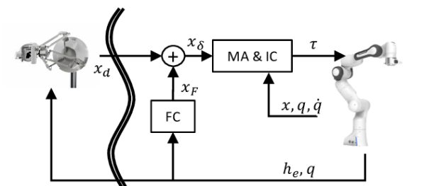
The FC is an admittance controller that modifies the trajectory input by the user to account for the interaction at the robots’ end-effectors, and it is based on the approach used in [22].
| (3) |
where is the desired inertia, is the estimated environmental interaction of the replica determined based on the measured wrench and the desired end-effector wrench . In general, the external interaction is estimated ; however, for the scope of this paper, solely includes gravity compensation. During bimanual manipulation, the desired end-effector wrenches from the two arms are expected to be in static equilibrium once the object gravitational wrench has been compensated; therefore, simplifies to the algebraic sum measured of the recorded wrenches (i.e., and ) projected in object the frame using the grasp matrix. is the desired environmental interaction, which is set to in all our experiment because we wanted the robot transparent if the motion was not generated by the operator (i.e., Medical Personnel). The acceleration is then integrated to obtained , as follows:
| (4) |
where is the maximum twist change allowed; thus, it constraints the admittance control to the reachable space around the robot state [22].
The pose is then added to to obtain . It is worth noting that it is also possible to add an additional element to and introduce an autonomous motion of the replica. In this case, and become adjustments to a nominal autonomous behaviour of the replica system.
The MA is done with an algorithm called SEIKO, which solves a Sequential-QP on the tangent space of the robot trajectory, ensuring that the next expected state is feasible (i.e., within the robots’ hardware limits) and does not pass through singularities. In the eventuality that any of these adverse conditions occurs, SEIKO returns the feasible solution which is closest to the desired state. The problem formulation follows, but the reader should refer to [22] to better understand the algorithm.
| (5) | ||||
is the desired state for the replica (i.e., posture and end-effectors’ wrenches), and the incremental change is the decision variable. is the position vector of all joints, is the contact wrenches at the end-effectors and is the number of robots in the Replica system, are the matrices and vectors defining the cost, equality and inequality constraints respectively. Our decision variable here is the incremental change , which is equivalent as optimising the rate change of the state . Therefore, the next state is . It is worth noting that this implies that the value of is modified only if the desired state provided in input to the optimisation is invisible.
The IC comprises a superimposition of four independent controllers, and all except the NLPD can be switched on and off without affecting the system stability. However, they might impact the accuracy and responsiveness of the replica. The replica torque command is computed as follows:
| (6) | ||||
and compensate for the nonlinear dynamics of the robot (i.e., centrifugal, Coriolis and gravitational forces). The PD is a passive impedance controller pulling the robot toward the desired joint configuration, and the implementation details are in Appendix. and are the measured joint positions and velocities for the robot arm; is the desired joint positions computed by MA. is the Jacobian at the desired interaction location for the arm. NLPD is the FIC that ensures the stability of the robot, is the Jacobians at the end-effector for the replica robot; is the measured Cartesian pose and is the vector of the measured velocities.
II-C Multi-Arm Coordination
The multi-arm coordination can be switched on online, allowing the user to control multiple arms with a single haptic device. It is executed at the MA level, where the optimisation constraints are added to the conditions required to maintain the grip on the object. These constraints evaluate the contact forces with the object and relative pose of the arms to maintain the grasp, derived by the grasp matrix and a simplified dynamic model of the object (i.e., geometry and mass)[22]. Additionally, a fifth controller is turned on in the IC, which enforces the relative pose between the arms. This controller is implemented as a PD task-space controller with a similar formulation of the PD in the joint-space controller used in Eq. (6).
| (7) | ||||
is the relative Jacobian between the limbs; and are the measured and desired relative pose of the limbs, respectively. is the measured relative velocity between them.
III Experimental Validation
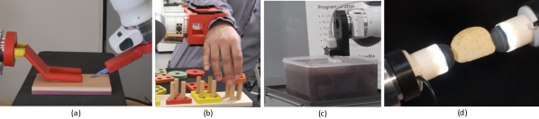
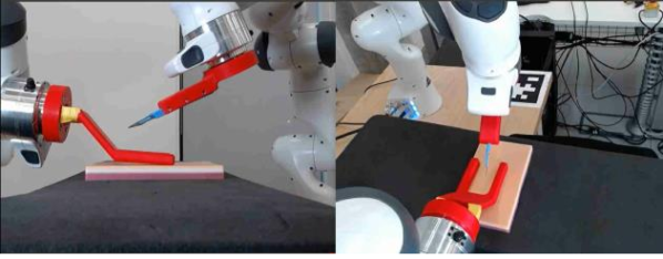
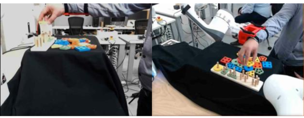
We have designed four experiments to evaluate the capabilities of the proposed method in medical robotics and identify limitations. The first experiment targets surgery, and it is specific to using a scalpel to cut a silicone model of the human skin (Fig. 4.a). The second experiment is a rehabilitation application, shown in Fig. 4.b. It evaluates the system’s capabilities to be deployed as a physical interface between the patient and the therapist during occupational therapy. The third experiment assesses the capabilities of the proposed method when performing an ultrasound scan (Fig. 4.c). We used a phantom made of gelatin balloons (i.e., bladders, water and fruit. The fourth experiments evaluate the system’s responsiveness in coordinated bi-manual manipulation of a fragile object (i.e., potato chip), evaluating the ability of the system to perform these tasks without reprogramming the controllers. However, it required the introduction of a soft force sensor at the end-effector (Fig. 4.d) to enhance the perception of the interaction forces. The parameters of the controllers are the same used in [22], and they are available in the Appendix A. We also want to remark that we are focusing on the linear components of the control because the angular components are expressed in quaternion, and the is not an intuitive way to visualise the results.
III-A Scalpel Experiment
The two end-effectors in Fig. 4.a have been developed for this experiment. One end-effector holds the scalpel, and the other keeps in place the skin model during the cutting. The operator executes multiple cuts on the phantom, trying to proceed straight when crossing previously made incisions. The cross-incision is particularly interesting because a perpendicular cut weakens the phantom. This experiment aims to validate the dexterity of the system during cutting, evaluate the impact of the system manipulability on the task, and the visual and haptic feedback performances.
The challenges of the scalpel experiment are the nonlinear soft-dynamics of interaction due both to the silicone of the phantom and the lateral flexibility of the scalpel blade, the 3D perception of the task before making contact, and the dexterity required to maintain the contact while executing long cuts in teleoperation.
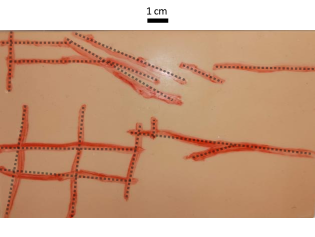
This first experiment highlighted the difficulties in handling long-distance 3D movements with multi-camera views (Fig. 5.a). Such interface for the operator does not allow the concurrent perception of the movements in the two planes. Notwithstanding, the situation improves once the scalpel makes contact with the object and the task acquires a predominant planar component. Fig. 6 shows how the cuts have undulatory shapes around the segment connecting the start and the endpoints with deviations that can reach up to for longer cuts. However, the clean cuts on the material (Fig. 7), the precise straight cut in some directions, and the presence of the undulatory behaviour in others seem to suggest that these deviations are due to the manipulability of the robots along this direction.

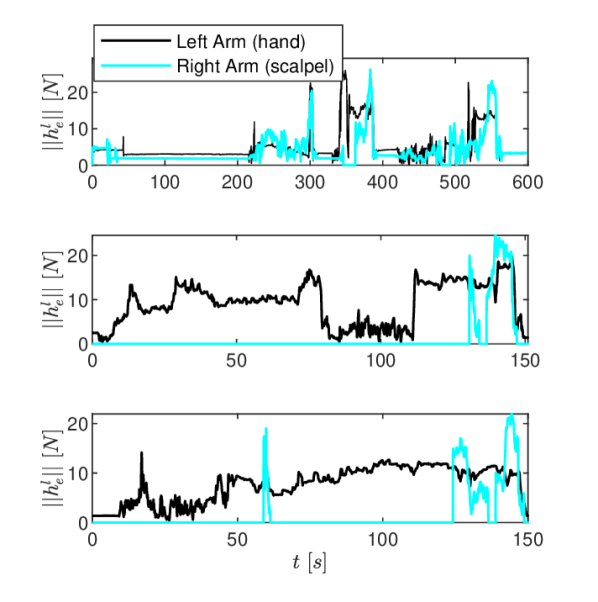
Finally, the operator also experienced difficulties with the haptic feedback for the left arm (i.e., hand end-effector), where there is the need for sustained interaction with the environment as shown in Fig. 8. In contrast, this effect has a lower impact on the scalpel arm due to the reduced force peaks and shorter interactions’ time, highlighted from the comparison of the signals’ plot in Fig. 8. Such phenomenon can be explained by the low-inertia of Sigma.7, which implies that the haptic feedback generates high tangential velocities in the master device. Thus, it requires active compensation from the user by increasing the interaction impedance and making the task tiring for the operator.
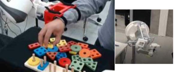
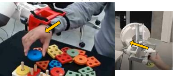
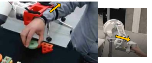
III-B Rehabilitation Experiment
The rehabilitation experiment is designed to evaluate the stability of the architecture when rigidly connected to a human via a brace while executing an activity simulating occupational therapy, as shown in Fig. 5.b.
The challenge of this test is the continuous trade-off between admittance and impedance behaviour. For example, if the patient takes the lead, the replica has to be transparent and behave as an admittance, while it has to switch to an impedance behaviour when the therapist intervenes to assist the patient. Such trade-off usually is extremely difficult for controllers because having an admittance controller acting on top of a non-rigid impedance controller tends to amplify the drift in the controller observer and eventually lead to instability.
The experiment is divided into three tasks in Fig. 9. The first investigates the transparency of the admittance controller to evaluate the level of compliance achievable without an additional end-effector force sensor by having the operator drive the robot to complete the task. The second task is about assistance with the operator assisting the patient in executing the task. Lastly, the third task is a disruptive interference from the operator, introducing perturbation to the user during the execution of the task.
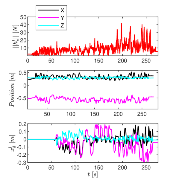
The norm of interaction forces () recorded in the experiment, the end-effector positions and the master controller linear command () are shown in Fig. 10. The proposed method is capable of switching from the full admittance behaviour during independent movement where peaks are about . This occurs in the first minute of the experiment when is close to 0. When the operator assists or perturbs the motions, the master error increases, generating the virtual force on the user. The assisted movements ends when . It is characterised by higher interaction forces compared to the autonomous motions, reaching peaks of about . In contrast, in the perturbation phase, where there is an opposition to the subject’s movements, the norm of the tangential force peaks.
III-C Ultrasound Scan Experiment
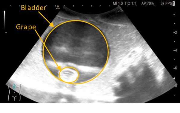
The ultrasound scan experiment evaluates the ability of the system to perform a remote diagnostic test, which requires the design of an end-effector for holding the ultrasound probe (Fig. 4.c). However, the available ultrasound scan does not allow remote control, so the experimental setup has been modified. This experiment is performed in the line of sight teleoperation. However, the phantom was placed above the operator’s line of sight to hinder the perception and promote the use of the video feedback from the ultrasound scan. We use a phantom made of commercial food gelatin mixed with psyllium husk to enhance the contrast. We have three layers of gelatin with different water components; the first has the recommended water to gelatin ratio. In the second layer, the amount of water is halved, and on the top layer, the water is reduced to one third. Multiple props are suspended in the mix. There are bladders made of water balloons with grape inside to mimic masses, and some fruit (grapes) is also distributed outside the bladder directly in the gelatine. It is worth noting that we have used a high-frequency probe that is not ideal for the quality of the image. However, it does not make any difference in evaluating the physical interaction stability and dexterity, which are objectives for this experiment.
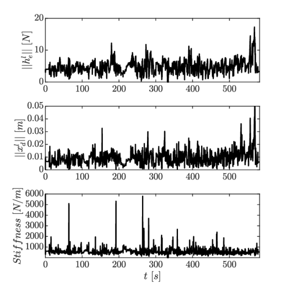
Fig. 11 shows the evolution of the interaction forces, the user input () and the stiffness of the replica arm, showing how the proposed method can dynamically adjust its stiffness to interact with the nonlinear environmental dynamics. The video also allows us better to appreciate how, once the contact is made with the phantom, the exploration can be driven mainly relying on the ultrasound monitor shown in 12. The main limitation in this experiment was that the available ultrasound did not allow remotely adjusting the image; thus, it requires being physically close to the patient.
III-D Bimanual Telemanipulation Experiment
The bimanual teleoperation experiments is designed to test the responsiveness and the accuracy of the coordination during bimanual teleoperation (Fig. 4.d). We have chosen a potato chip because it is at the same time brittle, stiff, and light enough to make gravity a negligible component of the interaction forces. We introduce a soft end-effector capable of providing an indirect estimation of the interaction force. We have mounted a sensor developed by the Bristol Robotics Laboratory called TACTIP [24]. It is based on a camera sensor placed inside a soft dome with a dotted geometric pattern, and the force estimation is obtained via the measurement of the pixel distance between the state of the deformed dome and the unperturbed state of the dotted geometrical pattern. The soft sensor enables the detection of subtle interaction forces, which could not be accurately estimated from the joint torques as in the previous experiments. The scope of this experiment is to validate the system’s transparent interaction performances by introducing an additional sensor at the robot end-effector.
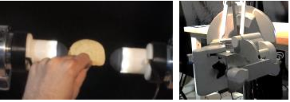
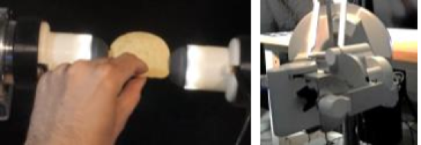
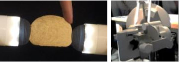
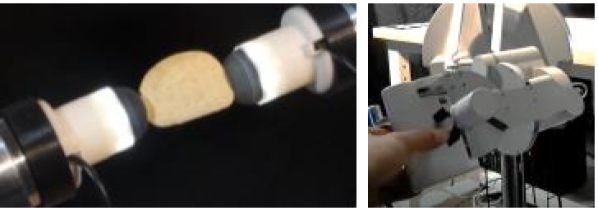
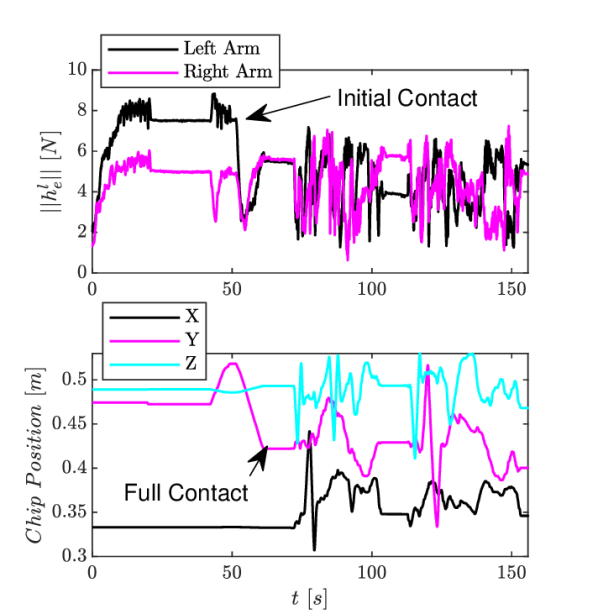
Fig. 13 shows the different stages of the experiment starting with the initial asymmetric contact made by the left arm, full contact once the right arm reached the potato chip, the user interaction with the object triggering the admittance behaviour of the controller, and the bi-manual telemanipulation showcasing the impedance behaviour of the proposed method. The interaction forces estimated from the joint torque compared with the position of the potato chip in Fig. 14 indicate that this is not a reliable way to estimate the interaction forces and the need of introducing the TACTIP end-effector for this task. We can observe multiple offsets in the contact forces estimated from the joints’ torques (Fig. 14) during and after the contact with the objects. These offsets occur where the environmental interaction does not solely generate movements. This latter condition observable for about starting at when the for the two arms are equal. Therefore, our experiments show that the flexibility of the proposed architecture allows overcoming the sensibility of the integrated admittance controller via the mounting of an instrumented end-effector that does not require any specific skillset in robotics.
IV Discussion
The experimental results indicate that the proposed modular method is adaptable to multiple applications without tuning. The operator can change the target application by mounting the proper end-effector and selecting the associated architecture configuration. However, the modality selection is at the module level and does not require any tuning of the inner parameters of each module; thus, it is well suited for applications such as medical technologies where we have an expert operator with no engineering background.
The surgery experiments validated the possibility of establishing safe interaction with the soft tissues with a scalpel. However, the current limitations of the visual and haptic feedback need to be overcome before this technology can be comprehensively evaluated in experiments using more complex phantoms and biological samples. The deployment of virtual and augmented reality could help provide a better 3D perception, which will require studying the most suited interface for providing comprehensive feedback and control on the system. Regarding the haptic feedback, employing the same robot in the master and the replica could help improve the user’s feedback. This haptics is currently compromised by the high end-effector motions induced in the master device (Sigma.7) due to its lower end-effector inertia than the replica (Panda).
The rehabilitation experiment showcased how the controller’s seamless trade-off between admittance and impedance behaviours allows robot-mediate collaboration between two human operators, which can also find application in other industries (e.g. manufacturing and logistics). Furthermore, it could also enable the deployment of commercial manipulators in rehabilitation, increasing the availability of robot-aided therapies and diversifying the market. Nevertheless, it also highlighted the same limitation in 3D perception in the visual feedback, which currently hinders the assistance from the remote operator.
The ultrasound scan experiment showcased that it is possible to accurately control the probe for conducting a scan. The feedback from the scan monitor is sufficient to conduct the test once the contact is made with the tissue; however, the 3D visual perception is essential to make contact with the desired anatomical district, which was possible thanks to the line of sight set-up used for this experiment. The main limitation to the deployment of this technology is the lack of remote control for the ultrasound scan, which limits the distance of the operator from the patient to the length of the probe. Nevertheless, this application is currently the closest to eventual clinical testing among the evaluated scenarios.
The bimanual telemanipulation experiments validated the possibility of having robot mediated collaboration while manipulating fragile objects by introducing a sensorised end-effector to detect the low interaction forces at the end-effector. This application is still in early development, but sensorised end-effector could be used for assistive technologies and applications requiring the handling of delicate objects such as in chemical laboratories.
Lastly, another major limitation encountered in all the experiments is the limited embodiment of the remote arm, which makes it difficult for the operator to understand the manoeuvrability and the residual range of motion dictated both by the robot kinematics and the presence of objects. A possible option to enhance the embodiment is to exploit the virtual haptic controller in the master () to provide such information on the residual range of motion as a virtual resistive force.
V Conclusion
We presented a preliminary evaluation of a modular control architecture that enables superimposition of manipulation and teleoperation in medical applications. Our experiments show that this method can provide robust physical interaction in a variegated set of scenarios without requiring a specialised robotic skill-set to be reprogrammed. However, they also show perception issues in visual and haptic feedback, and they need to be improved before clinical testing. The visual feedback from a multi-camera view is not ideal for 3D dynamic tasks, which could be improved with an augmented reality interface. The haptic feedback is not ideal due to the gap of end-effector inertia between the master and the replica robots used in our experimental setup.
Appendix A
The controllers and the parameters utilised in this work is the same that has been used in the experiments presented in [22]. The passive PD multidimensional controllers are constituted from multiple decoupled mono-dimensional controllers implemented as follows:
| (8) |
where is the state, is the desired state, and is the state velocity. The gains and which allows an intuitive tuning of the controllers.
The passive NLPD is also constituted by multiple decoupled mono-dimensional controller, which are defined as follows:
| (9) |
is the constant stiffness, is the state error, and is the tracking error when the force saturation occurs. , , controls the saturation speed, and control the starting of the saturation behaviour while approaching . The controllers parameters used in the controllers are reported in Table I.
| Parameter | Value | Unit | Parameter | Value | Unit |
|---|---|---|---|---|---|
| – | |||||
| degree | |||||
| degree | |||||
| degree | |||||
References
- [1] C. G. Rose, A. D. Deshpande, J. Carducci, and J. D. Brown, “The road forward for upper-extremity rehabilitation robotics,” Current Opinion in Biomedical Engineering, vol. 19, p. 100291, 2021. [Online]. Available: https://www.sciencedirect.com/science/article/pii/S2468451121000325
- [2] F. Ferraguti, N. Preda, A. Manurung, M. Bonfe, O. Lambercy, R. Gassert, R. Muradore, P. Fiorini, and C. Secchi, “An energy tank-based interactive control architecture for autonomous and teleoperated robotic surgery,” IEEE Transactions on Robotics, vol. 31, no. 5, pp. 1073–1088, 2015.
- [3] D. Laparidou, F. Curtis, J. Akanuwe, K. Goher, A. Niroshan Siriwardena, and A. Kucukyilmaz, “Patient, carer, and staff perceptions of robotics in motor rehabilitation: a systematic review and qualitative meta-synthesis,” Journal of neuroengineering and rehabilitation, vol. 18, no. 1, pp. 1–24, 2021.
- [4] H. Majidi Fard Vatan, S. Nefti-Meziani, S. Davis, Z. Saffari, and H. El-Hussieny, “A review: A comprehensive review of soft and rigid wearable rehabilitation and assistive devices with a focus on the shoulder joint,” Journal of Intelligent & Robotic Systems, vol. 102, no. 1, pp. 1–24, 2021.
- [5] N. Feizi, M. Tavakoli, R. V. Patel, and S. F. Atashzar, “Robotics and ai for teleoperation, tele-assessment, and tele-training for surgery in the era of covid-19: existing challenges, and future vision,” Frontiers in Robotics and AI, vol. 8, 2021.
- [6] O. Lambercy, R. Lehner, K. S. Chua, S. K. Wee, D. K. Rajeswaran, C. W. K. Kuah, W. T. Ang, P. Liang, D. Campolo, A. Hussain, et al., “Neurorehabilitation from a distance: can intelligent technology support decentralized access to quality therapy?” Frontiers in Robotics and AI, vol. 8, p. 126, 2021.
- [7] N. Hogan, H. I. Krebs, J. Charnnarong, P. Srikrishna, and A. Sharon, “Mit-manus: a workstation for manual therapy and training. i,” in [1992] Proceedings IEEE International Workshop on Robot and Human Communication. IEEE, 1992, pp. 161–165.
- [8] S. Crea, P. Beckerle, M. De Looze, K. De Pauw, L. Grazi, T. Kermavnar, J. Masood, L. W. O’Sullivan, I. Pacifico, C. Rodriguez-Guerrero, et al., “Occupational exoskeletons: A roadmap toward large-scale adoption. methodology and challenges of bringing exoskeletons to workplaces,” Wearable Technologies, vol. 2, 2021.
- [9] G. Tay, H.-K. Tan, T. K. Nguyen, S. J. Phee, and N. G. Iyer, “Use of the endomaster robot-assisted surgical system in transoral robotic surgery: A cadaveric study,” The International Journal of Medical Robotics and Computer Assisted Surgery, vol. 14, no. 4, p. e1930, 2018.
- [10] W. S. Ng, S. J. Phee, C. Seow, and B. L. Davies, “Development of a robotic colonoscope,” Digestive Endoscopy, vol. 12, no. 2, pp. 131–135, 2000.
- [11] W. Tian, Y. Wei, and X. Han, “The history and development of robot-assisted orthopedic surgery,” in Navigation Assisted Robotics in Spine and Trauma Surgery. Springer, 2020, pp. 1–3.
- [12] L. Vanlommel, E. Neven, M. B. Anderson, L. Bruckers, and J. Truijen, “The initial learning curve for the rosa® knee system can be achieved in 6-11 cases for operative time and has similar 90-day complication rates with improved implant alignment compared to manual instrumentation in total knee arthroplasty,” Journal of Experimental Orthopaedics, vol. 8, no. 1, pp. 1–12, 2021.
- [13] M. Minelli, F. Ferraguti, N. Piccinelli, R. Muradore, and C. Secchi, “An energy-shared two-layer approach for multi-master-multi-slave bilateral teleoperation systems,” in 2019 International Conference on Robotics and Automation (ICRA). IEEE, 2019, pp. 423–429.
- [14] K. K. Babarahmati, C. Tiseo, J. Smith, H. C. Lin, M. S. Erden, and M. Mistry, “Fractal impedance for passive controllers,” arXiv preprint arXiv:1911.04788, 2019.
- [15] G. Pennimpede, L. Spedaliere, D. Formica, G. Di Pino, L. Zollo, G. Pellegrino, V. Di Lazzaro, and E. Guglielmelli, “Hot spot hound: A novel robot-assisted platform for enhancing tms performance,” in 2013 35th Annual International Conference of the IEEE Engineering in Medicine and Biology Society (EMBC). IEEE, 2013, pp. 6301–6304.
- [16] A. Noccaro, A. Mioli, M. D’Alonzo, M. Pinardi, G. Di Pino, and D. Formica, “Development and validation of a novel calibration methodology and control approach for robot-aided transcranial magnetic stimulation (tms),” IEEE Transactions on Biomedical Engineering, vol. 68, no. 5, pp. 1589–1600, 2021.
- [17] C. Tiseo, W. Merkt, K. K. Babarahmati, W. Wolfslag, I. Havoutis, S. Vijayakumar, and M. Mistry, “Hapfic: An adaptive force/position controller for safe environment interaction in articulated systems,” IEEE Transactions on Neural Systems and Rehabilitation Engineering, pp. 1–1, 2021.
- [18] K. K. Babarahmati, C. Tiseo, Q. Rouxel, Z. Li, and M. Mistry, “Robust high-transparency haptic exploration for dexterous telemanipulation,” in Proc. IEEE International Conference on Robotics and Automation (ICRA), 2021.
- [19] C. Tiseo, Q. Rouxel, Z. Li, and M. Mistry, “Robust impedance control for dexterous interaction using fractal impedance controller with ik-optimisation,” in Proc. IEEE International Conference on Robotics and Automation (ICRA), 2022 (In Press).
- [20] ——, “Fine manipulation and dynamic interaction in haptic teleoperation,” arXiv preprint arXiv:2109.04524, 2021.
- [21] K. K. Babarahmati, C. Tiseo, Q. Rouxel, Z. Li, and M. Mistry, “Robust and dexterous dual-arm tele-cooperation using fractal impedance control,” arXiv preprint arXiv:2108.04567, 2021.
- [22] R. Wen, Q. Rouxel, M. Mistry, Z. Li, and C. Tiseo, “Collaborative bimanual manipulation using optimal motion adaptation and interaction contro,” arXiv preprint arXiv:2206.00528, 2022.
- [23] K. M. Lynch and F. C. Park, Modern robotics. Cambridge University Press, 2017.
- [24] N. Pestell, L. Cramphorn, F. Papadopoulos, and N. F. Lepora, “A sense of touch for the shadow modular grasper,” IEEE Robotics and Automation Letters, vol. 4, no. 2, pp. 2220–2226, 2019.