The BlackParrot BedRock Cache Coherence System
Abstract
This paper presents BP-BedRock, the open-source cache coherence protocol and system implemented within the BlackParrot 64-bit RISC-V multicore processor. BP-BedRock implements the BedRock directory-based MOESIF cache coherence protocol and includes two different open-source coherence protocol engines, one FSM-based and the other microcode programmable. Both coherence engines support coherent uncacheable access to cacheable memory and L1-based atomic read-modify-write operations.
Fitted within the BlackParrot multicore, BP-BedRock has been silicon validated in a GlobalFoundries 12nm FinFET process and FPGA validated with both coherence engines in 8-core configurations, booting Linux and running off the shelf benchmarks. After describing BP-BedRock and the design of the two coherence engines, we study their performance by analyzing processing occupancy and running the Splash-3 benchmarks on the 8-core FPGA implementations. Careful design and coherence-specific ISA extensions enable the programmable controller to achieve performance within 1% of the fixed-function FSM controller on average (2.3% worst-case) as demonstrated on our FPGA test system. Analysis shows that the programmable coherence engine increases die area by only 4% in an ASIC process and increases logic utilization by only 6.3% on FPGA with one additional block RAM added per core.
1 Introduction
System designers and computer architects are leveraging open-source hardware to create new processors and systems at an increasingly rapid pace. Within this movement, the RISC-V[29] ISA has been a key disruptive technology and has opened the door for computer designers, from individuals to corporations, to innovate and provide unique, bespoke systems.
As part of this movement, the open-source, Linux-capable, cache-coherent, 64-bit RISC-V BlackParrot [27] multicore processor has been developed. BlackParrot advanced the domain of processor design by adopting a software engineering approach for hardware with agile development, rapid design iteration, and continuous verification and testing to ensure a high-quality, high-performance design. The BlackParrot multicore processor has been silicon validated in a GlobalFoundaries 12-nm FinFET tapeout and FPGA validated on Xilinx Zynq and Xilinx Virtex Ultrascale+ HBM platforms [39].
In this paper, we describe the implementation of BlackParrot’s coherence system, called BlackParrot BedRock (BP-BedRock). We first provide a brief description of the BedRock cache coherence protocol, a family of directory-based invalidate cache coherence protocols using the common MOESIF coherence states. BedRock favors reducing protocol complexity rather than maximizing protocol concurrency and is well suited for small- (4-core) to medium-scale (32-core) multiprocessor designs.
We describe the implementation of BP-BedRock’s two directory-based coherence engines: (1) a directly implemented FSM, and (2) a microcode-programmable coherence engine. The microcode engine executes system firmware implementing one of the BedRock coherence protocols. The protocol code can be extended with custom system- and application-specific functionality and allows experimentation with new features post-fabrication.
The two coherence engine designs of BP-BedRock are analyzed and evaluated to understand the performance and complexity tradeoffs involved in introducing programmability into the coherence engine. We present request processing occupancy for each coherence engine and discuss how to accelerate request processing with coherence-specific ISA extensions. We provide area overheads from an ASIC implementation of BP-BedRock and show the programmable coherence engine increases die area by only 4% relative to a design utilizing the FSM-based engine. Analysis of an FPGA implementation shows the programmable engine increases logic LUT resource utilization by only 6.3% alongside one additional block RAM used per programmable engine. We evaluate the system-level performance of both coherence engine designs using the Splash-3 benchmark suite running atop a Linux-based OS on the BP-BedRock FPGA implementations, and show that the programmable coherence engine has a performance overhead of only 1% on average and 2.3% for the worst-case benchmark. These results encourage the exploration of programmability within the cache coherence engine and unique system features programmability can unlock.
The rest of this paper is organized as follows. Section 2 briefly presents the BedRock cache coherence protocol. Section 3 describes the implementation BP-BedRock’s coherence directory storage. Sections 4 and 5 describe the two cache coherence engine (CCE) implementations available in BP-BedRock. Section 6 presents the evaluation of the BP-BedRock system. Section 7 describes prior research related to BP-BedRock, and Section 8 concludes.
| Cache Action | Coherence Message | ||||||||||
| State | Load | Store | Inv | DATA | STW | WB | TR | ST-WB | ST-TR | ST-TR-WB | |
| I | ReqRd | ReqWr | CohAck/X | ||||||||
| S | Hit | ReqWr | InvAck/I | CohAck/M | |||||||
| E | Hit | Hit/M | NullWB/E | NullWB/X | DATA/X | DATA, NullWB/X | |||||
| M | Hit | Hit | DirtyWB/M | DirtyWB/X | DATA/X | DATA, DirtyWB/X | |||||
| O | Hit | ReqWr | CohAck/M | DirtyWB/O | DATA/O | DirtyWB/X | DATA/X | ||||
| F | Hit | ReqWr | CohAck/M | DATA/F | DATA/X | ||||||
| Dir State | Coherence Request | |||||
| ReqRd | ReqRd-NE | ReqWr from I | ReqWr from S | ReqWr from O/F | Replacement | |
| I | DATA to Req/E | DATA to Req/S | DATA to Req/M | |||
| S | DATA to Req/S | DATA to Req/S | Inv all S, DATA to Req/M | Inv other S, STWM to Req/M | ||
| E | STF-TRS-WB to Owner/F | STF-TRS-WB to Owner/F | STI-TRM to Owner/M | STI-WB to Req/I | ||
| M | STO-TRS to Owner/O | STO-TRS to Owner/O | STI-TRM to Owner/M | STI-WB to Req/I | ||
| O | TRS to Owner/O | TRS to Owner/O | Inv all S, STI-TRM to Owner/M | Inv other S and Owner, STWM to Req/M | Inv all S, STWM to Req/M | STI-WB to Req/I |
| F | TRS to Owner/F | TRS to Owner/F | Inv all S, STI-TRM to Owner/M | Inv other S and Owner, STWM to Req/M | Inv all S, STWM to Req/M | |
2 BedRock
The BedRock Cache Coherence Protocol [38] defines a family of directory-based invalidate cache coherence protocols using the common MOESIF cache coherence states and the coherence system components required to implement the protocol. This section provides a brief overview of the BedRock protocol, which the BP-BedRock system described in this paper implements. We refer readers to the protocol specification [38] for additional details on the design decisions of the protocol itself.
A BedRock system comprises one or more cache controllers (Local Cache Engines), one or more coherence directories (Cache Coherence Engines), and the coherence message networks. Each cache controller manages a single cache participating in the coherence protocol. The coherence directory is a standalone, inclusive, duplicate tag directory and acts as the point of serialization for all coherence transactions. Coherence is enforced using the Single-Writer, Multiple-Reader (SWMR) Invariant and Data-Value Invariant [20]. BedRock works with ordered or unordered networks and assumes the network implementation provides error free message delivery.
BedRock differs from a canonical directory protocol in a few subtle ways. First, the coherence directory has complete control over all changes to cache block coherence states, including invalidation and eviction of blocks from the cache controllers. The sole exception is a cache may silently upgrade a block from the Exclusive (E) state to the Modified (M) state on a write operation. Second, BedRock utilizes four unidirectional coherence networks, ordered in priority from highest to lowest: Response, Fill, Command, and Request. The Request and Response networks carry messages from cache controller to coherence directory, the Command network carries messages from directory to cache, and the Fill network carries cache to cache data transfers. Third, the cache controllers never hold a block in a transient state; all transient state is hidden from the controllers by the coherence directory’s processing flow. Lastly, the protocol design favors reducing complexity over maximizing concurrency.
2.1 Request Processing
The canonical processing flow for a BedRock request is divided into two stages. First, the directory is read and processed to determine if a cache block eviction (replacement) or invalidations are required. Then, the coherence engine determines the source of the cache block and initiates a cache to cache transfer, performs a memory read, or responds to the requesting cache with read/write permissions for the block if it already has a valid copy. The transaction completes when the cache controller receives the block and responds to the directory with a coherence acknowledgment. Advanced directory implementations may be able to overlap some of these actions or perform speculative memory accesses to reduce request processing latency.
2.2 Protocol Tables
Tables 1 and 2 present the complete tabular specification [32] of the BedRock MOESIF coherence protocol for the cache controller and coherence directory, respectively. Each table uses an "Action/State" notation to describe the behavior of the controllers. Given the current coherence state for a cache block (row) and an event (column), an entry in the table describes the action taken by the controller in response to the event and the next coherence state of the block at the controller. Blank entries indicate impossible state and event pairs for the controller.
2.2.1 Cache Controller Protocol Table
Table 1 describes how the cache controller responds to cache actions (load or store) and coherence commands. Cache actions may either hit in the cache or trigger a new coherence request. Coherence commands are directives issued by the directory to modify the state of a block and send a message in response on the Response or Fill network. An X state indicates a valid coherence state provided by the directory in the command message that is not known a priori by the cache controller.
2.2.2 Coherence Directory Protocol Table
Table 2 describes how the coherence directory processes coherence requests. The directory may also evict cache blocks from a controller to make room for a newly requested block (Replacement). Each "Action/State" entry describes the command messages sent by the directory to complete the request and the next state of the block at the directory. Some commands generate a response to the directory, and all transactions are finalized when the cache controller sends a coherence acknowledgment to the directory. The coherence state superscripts attached to some messages provide an associated coherence state for the message. For example, an STI-TRM message directs a cache controller to set the state of the target block to Invalid (I) and transfer that block in the Modified (M) state to another controller.
2.3 Ordering Transactions - Way Groups
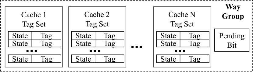
The BedRock protocol allows concurrent coherence transactions to independent cache blocks, but only one transaction at a time per group of related blocks. Two cache blocks are related if they belong to the same Way Group. A way group, shown in Figure 1, is the collection of cache blocks that map to the same cache set in any cache. A Tag Set is simply the pairs of coherence state and address tag for all ways within a single set of a single cache. The Pending Bit is set when a new transaction targeting a block in the way group starts and cleared when the active transaction completes. Transactions to way groups with a set pending bit must stall until the previous transaction completes. Requests targeting the same way group may be concurrently issued by many cache controllers and are serialized by the directory.
Every way group in the system is managed exclusively by a single coherence directory. In a system where all caches participating in coherence have the same organization with S sets, there are S way groups (one per cache set). A system with varied cache organizations has a number of way groups equal to the minimum number of cache sets across all caches.
Way groups guarantee that a coherence request will only cause changes to cache blocks within the target way group. Consequently, two transactions to two different way groups are guaranteed to be independent and can be processed concurrently. The use of way groups sacrifices protocol concurrency, but also eliminates transient states at the cache controllers that are typically required to handle that concurrency, thus simplifying the protocol for the cache controllers.111Future work will investigate efficient mechanisms to support concurrency within way groups.
3 BP-BedRock Directory
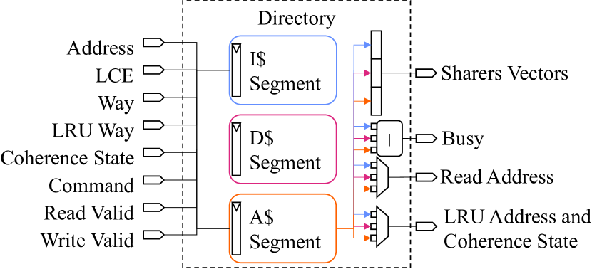
The BP-BedRock cache coherence engines (CCE) implement complete standalone duplicate tag directories. The organization of the coherence directory is identical in both the hardware-based (FSM) and microcode programmable (ucode) coherence engines. The directory is constructed from multiple directory segments with one segment per cache type in the system. BP-BedRock’s cache types are instruction, data, and optional coherent accelerator caches. Figure 2 shows a block diagram of the coherence directory. Systems without coherent accelerators do not instantiate the accelerator cache segment.
3.1 Coherence Directory Segment
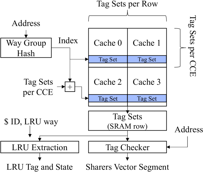
Figure 3 shows the organization of a BP-BedRock directory segment. Each segment stores a subset of the tag sets from all caches of a single type. The tag sets of all caches are spread evenly across the CCEs, with all tags sets in a single way group mapped to a single CCE. The tag sets of a single cache are stored in sequential rows in the directory SRAMs, and each row stores related tag sets from one or more caches. If the number of Tag Sets per Row is less than the number of caches being tracked by the directory segment, additional blocks of Tag Sets per CCE rows are added to track all caches.
The directory segment SRAM is a single-ported synchronous read-write memory. The width of the SRAMs are sized based on prior physical design work showing that two tag sets per row is PPA-efficient, however any power-of-two value is supported. The location of a cache block is easily computed using the cache’s ID and the block address, with the cache ID providing the first row of the cache’s tag set rows and the address providing a row offset within the block. The least significant bits of the cache’s ID also provides a horizontal offset into the target row.
3.2 Directory Operations and Access
A small FSM controls each directory segment and supports tag set entry reads, way group reads of all tag sets in a way group, tag set entry writes, and physical row clears. The directory segment organization provides single cycle writes and multiple cycle reads. Write operations have a latency of one cycle, and a new write may be issued every cycle. Tag set entry reads require two cycles. Way group reads require two or more cycles, depending on the total number of caches being tracked by the segment. In a BP-BedRock multicore, a way group read requires cycles for the default directory organization.
3.3 Tag Checker and LRU Extraction
BP-BedRock includes two modules that process the directory way group reads. The Tag Checker examines each directory row as it leaves the SRAM and produces the three Sharers Vectors. Each vector has one entry per cache, and the three vectors provide a cache hit bit, coherence state, and the cache way of the current LCE request’s cache block. The LRU extraction module processes each directory row and extracts the tag set entry at the LRU way for the specified LCE. If the directory segment requires multiple rows to store all cache’s tag sets for a single cache set, the LRU Extraction module outputs the LRU information only for the row containing the requesting LCE’s tag set. The LRU way input is provided in the coherence request from the cache controller.
4 BP-BedRock FSM CCE
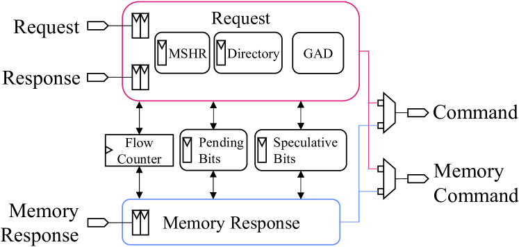
BP-BedRock’s FSM-based cache coherence engine (FSM CCE) is a direct hardware implementation of an FSM implementing the BedRock MOESIF coherence protocol of Table 2. Figure 4 shows the FSM CCE’s block diagram comprising Request and Memory Response state machines, Speculative Bits to track speculative memory reads, Pending Bits to enforce coherence transaction ordering for each way group, and a Flow Counter to provide memory network flow control.
4.1 Request FSM
The Request state machine processes coherence requests from the cache controllers. It instantiates a Miss Status Handling Register (MSHR) to hold processing state, the coherence directory, and a GAD module that processes the coherence directory output. The coherence directory implementation is described in Section 3. The MSHR and GAD modules are explained below, followed by a description of the state machine.
4.1.1 MSHR
| Flag | Description |
| Write Not Read | Write request |
| Uncached | Uncached request |
| Non Exclusive | Non-Exclusive request |
| Atomic | Atomic operation request |
| Atomic No Return | Atomic no return request |
| Cacheable Address | Request to cacheable memory |
| Pending | Pending bit set on last read |
| Cached Shared | Block cached in S at other LCE |
| Cached Exclusive | Block cached in E at other LCE |
| Cached Modified | Block cached in M at other LCE |
| Cached Owned | Block cached in O at other LCE |
| Cached Forward | Block cached in F at other LCE |
| Replacement | Replacement required |
| Upgrade | Request can be resolved with a permission upgrade |
The MSHR accumulates information related to the current LCE request during request processing. This information includes the request address, type, size, and requesting controller’s ID; information about any required cache block replacement; the current state, owner, and cache way of the requested block, and a set of control flag bits. The MSHR information is filled primarily from the request message begin processed and the required coherence directory read.
Table 3 lists the control flow flags stored in the MSHR. These flags come mostly from the current LCE request and the GAD module after a directory read, and are used to make efficient control flow decisions. The top six flags record properties of the current request. The Pending flag is set by the result of a pending bits read operation. The remaining flags are set after reading and processing the directory. The Replacement flag is set if a cache block replacement is required, and the Upgrade flag is set if the request can be resolved with a read/write permission upgrade to the requesting cache. The Cached State flags are set if the requested cache block exists in the corresponding state in any cache other than the requester.
4.1.2 GAD
During request processing, the FSM CCE reads the coherence directory to extract the current state of the target block across all caches in the system. The raw directory data is processed by the tag checker and output as the sharers vectors. The GAD, or Generate Auxiliary Directory Information, module consumes the sharers vectors and LRU information and computes a subset of the MSHR control flags; the owner, location, and coherence state of the target block, if an owner exists; and the cache way of the block within the requesting cache, if present. The GAD module takes a single cycle to execute and is invoked in the cycle following the coherence directory read.
4.1.3 Request FSM
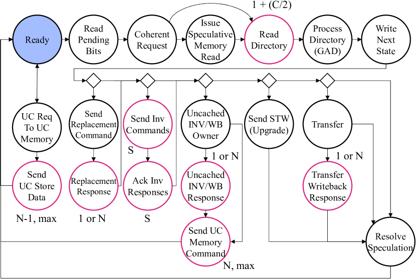
Figure 5 shows the FSM CCE’s request processing state machine. The FSM processes one request at a time and runs without interruption. States requiring multiple cycles to execute (outlined in magenta) are labelled with an execution latency. All other states execute in a single cycle. Execution begins in the Ready state, where requests are classified by request address as either coherent if they target cacheable memory or uncacheable if targeting uncacheable memory.
All requests targeting cacheable memory participate in the coherence protocol and require a coherence directory read. These requests are processed through an initial set of states that check the pending bits for an open transaction to the same way group, issue a speculative memory read for cacheable requests, read and process the directory, and then write the next state for the block into the directory. After initial processing, the FSM executes only those steps required by the request. Diamonds in the state machine diagram represent control flow decisions and have a cost of zero cycles. A key benefit of the FSM-based CCE implementation is that it can concurrently perform protocol processing and make control flow decisions, thereby incurring no overhead to transition between protocol processing steps.
Cacheable requests may require a cache block replacement to evict a block from the requesting cache or cache block invalidations to caches that contain valid copies of the requested block. After replacement and invalidations are complete, the request is resolved by either sending an upgrade command when the requester needs read/write permissions and has a valid read-only copy of the block, initiating a cache to cache transfer if the block is owned by another cache, or confirming that the block will be sourced from memory.
Uncacheable requests to cacheable memory invalidate and writeback the target block from all caches that contain a valid copy, before issuing the uncached operation to memory.
Uncacheable requests to uncacheable memory require minimal processing and result in either an uncached load or store being issued to memory. Uncacheable requests require one cycle to send the message header and first data beat plus one cycle per additional data beat. These requests do not participate in the coherence protocol.
4.1.4 Atomics
BP-BedRock supports atomics at the L1 and L2 caches, with L1 atomics enabled by default. L1 atomics result in the L1 data cache requesting write permission for the target block before the cache executes the operation after the block fill completes. RISC-V LR/SC sequences are handled similarly with the L1 data cache requesting write permissions at the LR operation, and are guaranteed to eventually succeed per the RISC-V specification. L2 atomic requests are executed at the L2 cache, with the coherence directory invalidating the target block from all L1 caches before the operation is sent to the L2 cache. All atomic operations are ordered by the coherence protocol (requesting write permissions for L1 atomic or LR/SC) or the coherence directory (serialization of requests for L2 atomic).
4.2 Pending Bits
The FSM CCE implements the pending bits attached to each way group as a collection of small counters external to the coherence directory. A way group’s pending bit is considered set if the counter is non-zero and unset if the counter is zero. Pending bit writes are synchronous, while reads are asynchronous and support write to read forwarding. The CCE increments a way group’s pending bit when beginning request processing or issuing a memory command. Pending bits are decremented by consuming memory responses or coherence acknowledgment responses, and when the CCE finishes processing uncached requests to coherent memory.
4.3 Speculative Bits
The Speculative Bits record information about speculative memory reads issued during request processing. There is one Speculative Bits entry per way group. Each entry includes a coherence state, a speculative bit, a squash bit, and a forward-modified bit. The CCE sets a way group’s speculative bit when issuing a speculative memory request and clears the bit once the source of the cache block is determined after reading the directory. A speculative memory request will be squashed if the squash bit is set, forwarded with the stored coherence state when the forward-modified bit is set, or forwarded without modification if all bits have been cleared. Memory requests are squashed when the block can be supplied by a cache to cache transfer.
4.4 Memory Response FSM
The Memory Response FSM is a three-state multi-cycle state machine that processes BP-BedRock Memory Response messages returning from the L2 cache / memory or I/O devices. The state machine examines each memory response as it arrives and either forwards it to the appropriate LCE or sinks the response from the memory network. All memory responses include a speculative bit that is set if the response was generated by a speculative memory command. Speculative responses are either squashed or forwarded to a cache controller, as explained above. Non-speculative responses either carry data from a cached or uncached read, which are forwarded to the requesting controller, or are header-only responses to memory write commands, which are sunk by the FSM.
5 BP-BedRock ucode CCE
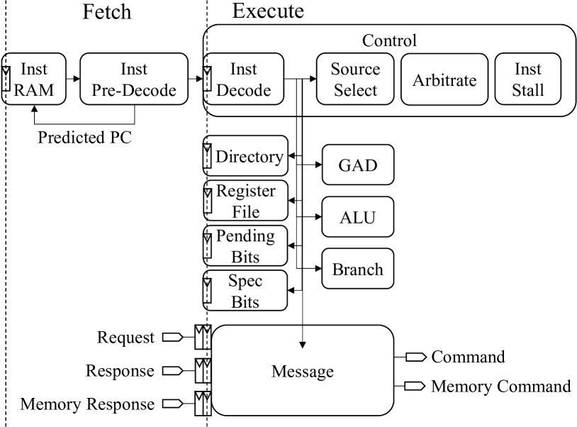
The BP-BedRock microcode-programmable CCE (ucode CCE) is a user-programmable coherence engine with a two-stage fetch-execute pipeline, 64-bit general purpose registers and datapath, specialized coherence protocol processing logic, and a custom RISC ISA specialized for coherence protocol processing. The ucode CCE is specialized for the BedRock coherence protocol and provides programmability to enable system- and application-specific functionality on top of the coherence protocol. Figure 6 shows a block diagram of the BP-BedRock ucode CCE. The programmable CCE reuses many modules from the FSM CCE, including the Coherence Directory, GAD, Pending Bits, and Speculative Bits. BP-BedRock provides microcode implementations of the BedRock MOESIF, MESI, MSI, and EI protocols. The baseline MOESIF protocol with speculative memory access closely matches the processing flow of the FSM CCE implementation. The remainder of this section describes the microcode ISA and modules unique to the ucode CCE.
5.1 Microcode ISA
| Op | Format | Function |
| sf, sfz | op flag | flag = 1, flag = 0 |
| andf, orf | op flag flag gpr | rd = flag op flag |
| nandf, notf | op flag flag gpr | rd = flag op flag |
| notf | notf flag gpr | rd = flag |
| bf | bf tgt flag [flag…] [pt] | pc = tgt if all flags 1 |
| bfnot | bfnot tgt flag [flag…] [pt] | pc = tgt if all flags 0 |
| bfz | bfz tgt flag [flag…] [pt] | pc = tgt if any flag 1 |
| bfnz | bfnz tgt flag [flag…] [pt] | pc = tgt if any flag 0 |
| rdp | rdp addr=<a> | pf = pending_bits[addr] |
| rdw | rdw addr=<a> lce=<l> lru_way=<w> [src=<ra>] | produce sharers, lru info, etc. |
| rde | rde addr=<a> lce=<l> way=<w> [src=<ra>] dst=<rd> | rd = addr, sh_states[lce] = state |
| wdp | wdp addr=<a> p=<0,1> | pending_bits[addr] +/- 1 |
| clp | clp addr=<a> | pending_bits[addr] = 0 |
| clr | clr addr=<a> lce=<l> | clear directory row |
| wde | wde addr=<a> lce=<l> way=<w> [src=<ra>] state=<s> [state_imm] | dir[addr, lce] = [tag, state] |
| wds | wds addr=<a> lce=<l> way=<w> [src=<ra>] state=<s> [state_imm] | dir[addr, lce] = […, state] |
| gad | gad | execute GAD unit |
| wfq | wfq queue [queue…] | Wait for message on queue |
| pushq | pushq queue cmd addr=<a> lce=<l> way=<w> [src=<ra>] wp=<0,1> spec=<0,1> | push message to queue queue |
| popq | popq queue [wp] | dequeue message, write pending bit |
| poph | poph queue rd | capture message header |
| specq | specq spec_cmd addr_sel [state] | speculation bits operation |
| inv | inv | send invalidations |
The ucode CCE executes a custom RISC instruction set architecture (ISA) specialized for coherence protocol processing. The ISA is divided into a Base ISA and a Coherence ISA. The Base ISA contains standard RISC instructions for arithmetic, branch, and data movement operations. The Coherence ISA contains instructions specialized for coherence processing, such as manipulating control flags, flag-based control flow, reading and writing the coherence directory, and sending or receiving messages. All branch instructions are tagged with a static taken/not-taken prediction bit and the branch mispredict penalty is one cycle. Table 4 lists the BP-BedRock Coherence ISA instructions, which are divided into Flag, Directory, and Queue operations. Directory read and queue operations may take more than one cycle to execute depending on functional unit conflicts and latencies, while all other instructions execute in a single cycle.
A key contribution of BP-BedRock is its specialized Coherence ISA that accelerates protocol processing by invoking coherence-specialized functional units. These instructions are critical to closing the performance gap between the ucode and FSM-based CCEs.
5.1.1 Flag Instructions
Flag instructions can set or clear flags, perform logic operations on pairs of flags, and make control flow decisions based on the state of a programmer-selected set of flags. The most important of these are the flag-based branch instructions (bf, bfz, bfnz, bfnot). Each flag-based branch examines a set of programmer-selected MSHR flags, encoded in a bitmask within the instruction, and branches the microcode PC to the supplied target PC if the branch condition is met. A single flag-based branch instruction is able to replace a sequence of regular branch instructions, thereby accelerating common protocol processing control flow decisions.
5.1.2 Directory Instructions
Directory instructions accelerate directory read, write, and processing operations by invoking the coherence directory and GAD modules. Directory way group reads require only cycles to execute, compared to tens or hundreds of cycles that would be required by a general-purpose implementation of the same routine using for loops. Pending bit and directory entry reads require one and two cycles, respectively. Directory writes execute in a single cycle. The GAD module executes in a single cycle, compared to a cost of tens of instructions to implement equivalent logic in general-purpose RISC code. Additionally, the flag outputs of the GAD module never need to be recomputed by the microcode program, saving many additional cycles for every flag-based branch instruction.
5.1.3 Queue Instructions
Queue instructions enable efficient sending and receiving of coherence protocol and memory messages. The ucode CCE is able to send and receive messages with a cost of one cycle per message header or data beat. The invalidate (inv) instruction further accelerates coherence protocol processing by invoking a small hardware-implemented state machine within the ucode CCE’s message unit to efficiently send invalidation commands to all caches with a Shared (S) copy of the specified cache block at a rate of one message per cycle. A general-purpose RISC routine for invalidations would require at least a few instructions per invalidation sent if executed in a tight for loop.
5.1.4 Programming the CCE
The CCE is programmed at the microcode level. A custom assembler applies a limited set of instruction transformations to map available software pseudo-ops into hardware-implemented microcode instructions. BP-BedRock’s MOESIF protocol microcode is only 125 instructions, which includes support for uncacheable access to both cacheable and uncacheable memory and system initialization.
5.2 Instruction Fetch and Predecode
The Instruction RAM and Predecode modules comprise the Fetch Stage of the ucode CCE. The instruction RAM unit contains the microcode instruction memory and logic to determine the next microcode program counter (PC). The predecode module examines the just fetched instruction to detect branches and provides a predicted PC to the fetch logic. A stall in the Execute stage halts instruction fetch, and a branch mispredict squashes the just fetched instruction while redirecting fetch to the correct PC.
5.3 Instruction Decode and Stall
The Instruction Decode unit expands the current narrow microcode instruction into a wider decoded instruction containing control signals for the Execute stage’s functional units.
The Instruction Stall unit detects functional unit hazards and message stalls due to busy or empty networks. It outputs a stall signal that is routed to the Fetch stage and the instruction decoder, causing the current instruction to replay in the following cycle. Functional unit hazards occur when the ucode engine and message unit access the same resource.
5.4 Source Select and Arbitration
The source select module routes operands to the ucode CCE’s functional units as specified by he current instruction. Source operands may come from the GPRs, MSHR, inbound messages, or directory outputs.
The arbitration unit controls access to the coherence directory, pending bits write port, and speculative bits read port. In a given cycle, each of these three resources may be used by either the microcode instruction or the message unit. The message unit has priority over the ucode engine for each resource, causing the ucode engine to stall when it loses arbitration, which helps guarantee deadlock freedom in the coherence protocol.
5.5 Register File
The Register File stores the CCE’s Miss Status Handling Register (MSHR), eight 64-bit general purpose registers (GPRs), a coherence state register, and an auto-forward control register. The coherence state register holds a default coherence state that can be used as a source operand for coherence and memory commands. The auto-forward control register is a single bit register that controls whether the ucode CCE’s message unit will automatically process memory response messages. It is set by default, but can be disabled via the microcode.
5.6 Functional Units
The ucode CCE includes functional units tailored for both general purpose and coherence specialized execution. The Coherence Directory, Pending Bits, Speculative Bits, and GAD modules are all re-used without modification from the FSM CCE design and are described in Section 4.
5.6.1 ALU and Branch
The Arithmetic Logic Unit (ALU) has a 64-bit datapath and supports add, subtract, shift, and bitwise operations. The hardware ALU is very simple, and many operations available to the programmer are supported at the software level as pseudo-ops using assembler transformations.
The Branch unit resolves branch operations and validates the Fetch stage’s speculative fetch predictions. The result of the branch is compared to the branch prediction made in the Fetch stage to determine if a mispredict occurred. Mispredicts redirect the fetch stage to the resolved PC and result in a single cycle bubble in the execute stage.
5.6.2 Message
The Message unit is responsible for sending and receiving all coherence and memory messages. It can write the pending bits, read the speculative bits, and write the coherence directory. It also contains a memory credit flow counter that limits the number of outstanding memory commands. The message unit has two state machines that process memory response messages and send or receive messages as directed by the microcode program. The memory response state machine is identical to the one found in the FSM CCE. However, it can be disabled via the microcode program by clearing the auto-forward register in the register file. The other state machine sends and receives messages based on the currently executing instruction. This FSM also implements the specialized invalidation routine logic that can issue one invalidation per cycle.
5.7 Request Processing
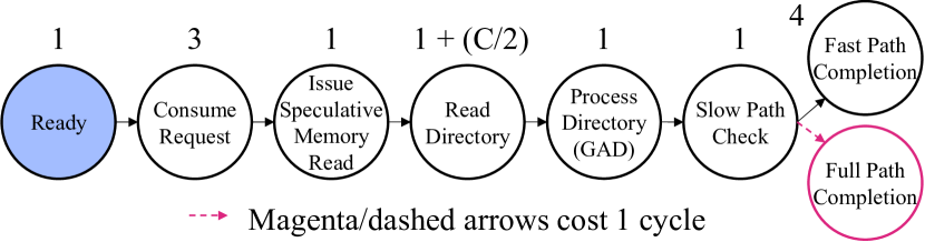
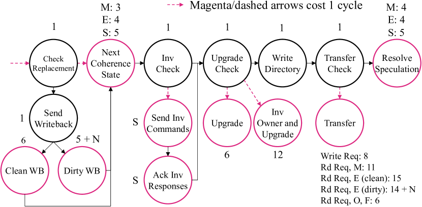
The ucode CCE’s microcode programs implement an execution flow similar to the FSM CCE. Figures 7 and 8 show the MOESIF protocol microcode processing flow for cacheable requests. Each circle represents one or more microcode instructions and is called a subroutine, and each subroutine is labelled with its execution latency in cycles. Transitions between states that are black/solid cost zero cycles and those that are magenta/dashed cost one cycle, which indicate a branch mispredict. States outlined in magenta require more than one cycle to execute.
Figure 7 shows the initial subroutines executed by the MOESIF protocol for all coherence requests to cacheable memory. The microcode is optimized to handle load requests to blocks in the Invalid state, which is called the Fast Path. All other requests are handled by the Full Path. A fast path request is fulfilled by a memory access, which is issued speculatively before the directory read occurs. The directory read latency is cycles. Following the directory read, a single cycle is required to confirm the request does not require the full path for processing before finalizing the past path processing.
The ucode CCE MOESIF protocol continues processing non-fast path requests using the flow shown in Figure 8. These requests either target a block that is already cached somewhere in the system, require a cache block replacement at the requesting LCE, or are write requests. The total execution latency of all requests can be computed directly from the processing flow diagrams by adding the cost per state visited plus one cycle per branch mispredict transition (magenta/dashed arrow). The Compute Next Coherence State and Resolve Speculation subroutines require a variable number of cycles to execute, depending on the coherence state that will be supplied to the requesting cache. Invalidations are offloaded to the message unit and require a single cycle per invalidation sent or received, for a total of cycles to complete all invalidations. Writebacks during cache block replacement or from a transfer require N cycles to forward the N cache block data beats from the LCE response to the memory network. The Transfer subroutine occupancy depends both on the type of request (read or write) and the coherence state of the block at the directory. Request processing completes after performing an Upgrade, Transfer, or Resolving Speculation (indicated by states with no out transitions).
6 Evaluation
6.1 Protocol Verification
The BedRock cache coherence protocol is similar to, yet subtly different from, commonly understood directory-based protocols [20, 33, 25, 34, 8]. Therefore, it is important that the protocol itself is shown to be correct. BedRock’s MESI protocol has been verified correct using CMurphi [26], an improved version of the Murphi [9] model checking framework, for a system with eight coherent caches and a single coherence directory. BedRock’s CMurphi description models a single cache block, a single coherence directory, and unordered networks. These assumptions are valid because, by definition, cache coherence is constrained to a single memory location, BedRock’s coherence directories operate independently from one another in a multi-directory system, and every cache block is managed by a single directory.
6.2 BedRock Directory Overhead
| Caches | BP-BedRock | Complete | Coarse (8-bits) |
| 2 | 6.25% | 7.81% | 7.81% |
| 4 | 6.25% | 7.81% | 9.38% |
| 8 | 6.25% | 9.38% | 9.38% |
| 16 | 6.25% | 10.94% | 9.38% |
| 32 | 6.25% | 14.06% | 9.38% |
| 64 | 6.25% | 20.31% | 9.38% |
BP-BedRock utilizes a standalone, duplicate tag coherence directory. However, this is not the only choice of directory organization that could have been made. Therefore, we investigate the coherence directory storage overhead of BP-BedRock’s directory and compare it to the overhead of standalone complete and coarse directories [20, 36]. The analysis assumes 8-way associative L1 caches with 64 sets and 64-byte cache blocks, which are the default for BP-BedRock, with private instruction and data caches per core. The system uses 28-bit physical address tags and 3-bit coherence states. Table 5 shows the results of the overhead analysis. BP-BedRock’s duplicate tag directories have a constant storage overhead of 6.25%, which is less than both the complete and coarse directories. This property is greatly beneficial for the physical design of BP-BedRock, where a slice of the coherence directory is instantiated on each multicore tile and the multicore is constructed by instantiating tiles in a 2D mesh. The constant overhead results in a fixed directory size per tile, regardless of core count, which enables the use of a hierarchical, tile-based backend design flow for ASIC implementations.
6.3 CCE Request Processing Occupancy
| Request | LCE State | Directory State | FSM CCE Occupancy (cycles) | ucode CCE Occupancy (cycles) |
| Read Excl | I | I | ||
| Read NE | ||||
| Read | I | S | ||
| E (clean) | ||||
| E (dirty) | ||||
| M | ||||
| O, F | ||||
| Write | I | I | ||
| S | ||||
| E, M | ||||
| O, F | ||||
| Write | S | S | ||
| O, F | ||||
| Write | O, F | O, F |
The BP-BedRock coherence engines both implement the BedRock MOESIF cache coherence protocol. The FSM CCE is a direct hardware implementation of the protocol’s request processing flow, while the ucode CCE executes a microcode program implementing the protocol and provides flexibility to add additional processing and functionality to protocol processing. The throughput and latency of cache coherence engines are important to overall system performance, therefore we first analyze each coherence engine’s request processing occupancy.
Table 6 presents the request processing occupancy for both coherence engines. Processing occupancy, given in cycles, is the number of cycles required in a best-case, no-contention execution to process a coherence request. Three constants are used in the processing occupancy computations: C is the number of cores in the multicore processor, N is the number of data beats required to send a full cache block across the coherence network data channels, and S is the number of caches holding a block in the Shared (S) coherence state, called the sharers. The data presented are the number of cycles that the coherence engine is busy processing a single request, and processing occupancy are derived directly from Figures 5, 7, and 8. The numbers presented assume that a cache block eviction (replacement) is not required. Occupancy provides insight into the maximum achievable throughput of the coherence engine designs. The request occupancy does not include the time required to process memory responses, which are handled by a separate state machine in both designs that operates concurrent to request processing. Network time is also excluded as the time for messages to transit networks is the same for both designs.
6.3.1 FSM CCE Occupancy
The FSM CCE has a base request processing occupancy of cycles, incurred by all requests, as it moves from Ready through Write Next State in Figure 5. During this initial processing, the request is consumed, the directory is read and processed, and the directory entry for the requesting cache is updated with the final next state for the block. Then, depending on the specific request and state of the target block in the system, the FSM executes only those steps required to complete the transaction. The diamonds in Figure 5 indicate control flow decisions, but have a cost of zero cycles. The key performance advantage of the FSM-based design is that control flow decisions are effectively free; in any given state, the next state is computed concurrently with the protocol processing occurring in the state. Thus, after executing the initial processing, the added cost to complete a request is simply the cost of the remaining states visited. The worst-case request, in terms of occupancy, is a write request to a block in the O or F state, which is owned by a single cache but shared by many caches and may be present in every single cache in the system. A cache block replacement adds either two or cycles of processing time for clean and dirty blocks, respectively.
6.3.2 ucode CCE Occupancy
The ucode CCE incurs execution overheads relative to the FSM-based CCE primarily due to its inability to execute protocol processing and control flow in the same instruction and the fact that each control flow decision requires a separate instruction. As described in Section 5.7, the MOESIF microcode program includes a fast path (Figure 7 to process regular reads for blocks in the Invalid state. This path has an execution overhead of only four cycles compared to the FSM-based coherence engine. The fast path is effectively a single basic-block of microcode, and therefore can be executed at a rate matching that of the FSM-based engine. However, all other requests must branch to the full path, shown in Figure 8, which is capable of performing replacements, invalidations, and cache to cache transfers. The base occupancy for both paths is only one cycle greater than the FSM-based engine at cycles. Requests processed by the full path have occupancy overheads between 15 to 25 cycles. Significant overheads are incurred for subroutines that require multiple control flow decisions. In particular, determining the proper next coherence state for the block, resolving the outcome of the speculative memory access, and initiating cache to cache transfers all add significant latency to request processing. A cache block replacement adds either seven or cycles of processing time for clean and dirty blocks, respectively.
6.3.3 Discussion
Designing a microcode programmable coherence engine with processing occupancy equivalent to an FSM-based design remains an open challenge. The ucode CCE’s contribution to this problem is its use of coherence-specific ISA extensions to efficiently offload common coherence protocol operations, such as reading and processing the directory and performing invalidations, to specialized functional units. Despite the control flow overheads experienced by the ucode CCE, processing occupancy overheads are limited to tens of cycles through the use of coherence-specific instructions. The coherence directory hardware accelerates directory operations, replacing a potentially expensive loop-based microcode routine requiring tens to hundreds of cycles with a comparatively inexpensive fixed-latency execution. Similarly, constructing and sending coherence messages are executed by the specialized message unit at a rate of one cycle per header or data beat. A reasonable software implementation might require tens of cycles per message send or receive using memory-mapped messaging queues. The ucode CCE’s inclusion of coherence-specialized functional units points to a promising path forward for programmable coherence engines that are specialized for protocol processing yet flexible enough to enable unique system features.
6.4 Area, Utilization, and Timing
| Design | Component | Resource | Overhead |
| ASIC | Multicore | Die Area | |
| Tile | 4.28% | ||
| CCE | 31.08% | ||
| FPGA | Multicore | Logic LUTs | 6.32% |
| BRAM | 1.54% | ||
| Tile | Logic LUTs | 7.08% | |
| BRAM | 1.54% | ||
| CCE | Logic LUTs | 66.19% | |
| BRAM | 1 per CCE |
BlackParrot, including BP-BedRock, has been silicon validated using GlobalFoundries 12nm FinFET process and FPGA validated in an 8-core configuration for each coherence engine using a Xilinx Ultrascale+ VCU128 development platform[39]. Table 7 provides area and resource utilization overheads for ASIC and FPGA-based designs. The overheads listed are normalized to designs using the FSM-based coherence engine. The more efficient ASIC implementations show the introduction of programmability into the coherence system comes at a small area cost of only 4.08% extra die area for the entire multicore and a 4.28% increase per BlackParrot Tile. Each BlackParrot Tile comprises a BlackParrot core, its 32 KiB L1 D$ and I$, a 64 KiB slice of the distributed L2 cache, the on-chip networks and routers to connect tiles, and an instance of the BP-BedRock coherence engine and directory. The L2 cache acts as a memory-side buffer and does not participate in the coherence protocol. All SRAM macros are hardened in the ASIC flow, and the multicore is a 2-D mesh of Tiles with minimal additional surrounding logic. These area overheads are largely due to the addition of a microcode instruction SRAM. In the FPGA implementations, the logic utilization increases by only 6.32% and 7.08% for the entire multicore and per tile, respectively, when using the ucode CCE. Each programmable CCE additionally requires a single 18 Kib block RAM resource, which amounts to a 1.54% increase in 18 Kib block RAM resources22236 Kib block RAMs are counted as two 18 Kib block RAMs for this analysis.. Additionally, both coherence engine implementations meet the same design target frequency in both the ASIC and FPGA implementations.
6.5 Splash-3 Performance
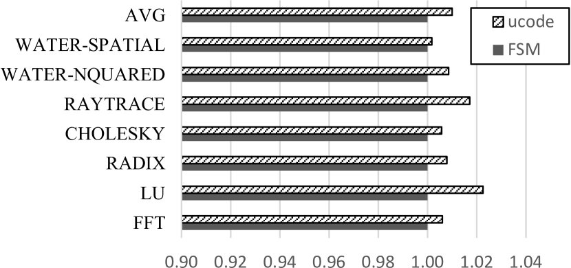
To compare the impact of coherence engine design on system performance we ran a collection of benchmarks from the Splash-3 [30] suite on FPGA-based 8-core BP-BedRock systems with the FSM-based and microcode programmable coherence engines. The benchmarks were compiled for the RISC-V ISA using gcc targeting a Linux environment, and invoked to execute on all 8 available processor cores. The FFT, LU, RADIX, and CHOLESKY programs are smaller kernel programs, while the remaining three programs are larger application programs. We refer readers to [30] and [37] for more details on the synchronization and memory characteristics of these programs. Wall-clock execution time for all benchmarks ranged between tens of seconds and tens of minutes.
The BP-BedRock FPGA designs instantiate an 8-core BlackParrot multicore with 32 KiB L1 instruction and data caches, a 512 MiB shared L2 cache, and 2 GiB of HBM-based main memory. The multicore instance was clocked at 50 MHz. The programs were run in a Linux-based OS environment constructed using BuildRoot [5] and Busybox [6] with Linux kernel v5.15 [35] and OpenSBI v1.0 [22].
Figure 9 shows total execution time measured using the time utility for each benchmark, averaged over three runs, and normalized to the FSM-based multicore design. Our experiments show that the microcode programmable coherence engine is within 1% of the hardware-based FSM’s performance on average, and only 2.3% slower at worst. Despite having a 15 to 25 cycle best-case processing occupancy overhead, the ucode CCE multicore experiences a very small performance slowdown. Intuitively, this result makes sense as any program with reasonably good cache utilization and low miss rates will only invoke the coherence system on a cache miss. If misses are infrequent, the overall impact on system performance will be small, which follows directly from the standard average memory access time computation.
This result indicates a promising path forward for further exploration of programmable coherence engines. Careful design of the protocol processing paths can keep a programmable coherence engine competitive with a fixed-function engine, while the flexibility of a programmable system can unlock exciting new system features.
7 Related Work
BP-BedRock is most closely related to prior research studying programmable cache coherence systems. Programmable coherence systems have been explored at many levels. At one extreme, software-managed cache coherence [31, 17, 16, 24] and systems without any hardware coherence support [13, 10] rely on the system or application programmer to implement correct coherence mechanisms – no easy feat! BP-BedRock provides flexibility to the system designer through its programmable coherence engine, but does not require the application developer to manage coherence.
The benefits of programmable controllers are evaluated in [19, 18], and controller designs include the MAGIC node controller [14, 11, 15, 12], Wisconsin Typhoon [28], Sun Microsystems S3.mp [21], and the Piranha chip multiprocessor [4]. Piranha and S3.mp use microprogrammed coherence engines that are more specialized than BP-BedRock, Typhoon uses an off the shelf commodity processor as the protocol engine, and MAGIC uses a customized MIPS-based RISC processor as the node controller.
| Property | MAGIC | BP-BedRock |
| Base ISA | MIPS | Custom RISC |
| ISA Extensions | Bitfield Op | Directory Rd/Wr |
| Set/Test Bit | Flag Op | |
| Tx/Rx Message | Tx/Rx Message | |
| GPRs | 32 x 64-bit | 8 x 64-bit |
| Data $ | 32 KiB off-chip | none |
| Instruction $ | 16 KiB on-chip | 1.5 KiB |
| Data Buffers | 2 KiB 6-port SRAM | none |
| Directory Memory | none | 3.625 KiB |
| Protocol Agnostic | yes | no |
| Message Passing | yes | no |
| Coherence Type | Distributed Directory | Distributed Directory |
| Coherence Domain | Inter-node | Multicore |
| Coherence Model | All memory blocks | Only cached blocks |
| HW Address Translation | no | no |
| Interrupts | no | no |
| Open Source | no | yes |
| Operation | BP-BedRock | MIPS (MAGIC) |
| Directory Read | ||
| Invalidation | ||
| Branch | 1 | 1 |
| Flag Branch | 1 | – |
| Request (Directory State) | BP-BedRock | MIPS (MAGIC) |
| Read (I) | 16 | 184 |
| Read (S) | 30 | 184 |
| Read (M) | 36 | 219 |
| Write (I) | 27 | 184 |
| Write (S) | ||
| Write (M) | 31 | 198 |
BP-BedRock is most similar to MAGIC in that both designs are effectively small, specialized integer-only RISC ISA engines. Unlike MAGIC, which is designed as a generic protocol processor, BP-BedRock’s programmable engine is designed to efficiently implement the BedRock coherence protocol while enabling unique system- and application-specific functionality via programmable routines executing alongside protocol processing. BP-BedRock is not designed to support arbitrary coherence protocols or shared memory solutions. Table 8 compares the architectural properties of MAGIC and BP-BedRock. BP-BedRock includes dedicated directory storage and a microcode instruction memory instead of general purpose instruction and data caches. Both designs use specialized RISC instruction sets with similar extensions for bit manipulations and message send and receive operations, however, BP-BedRock also includes specialized instructions for reading and processing the coherence directory and to perform efficient flag based control flow. Neither BP-BedRock or MAGIC supports virtual memory or interrupts. Tables 9 and 10 provide quantitative comparisons between BP-BedRock and a MIPS-based protocol processor like MAGIC. Table 9 compares the latency of selected directory operations such as reading and processing a duplicate tag directory, issuing invalidations, and control flow operations. BP-BedRock’s specialized functional blocks enable highly efficient coherence directory reads, while a MIPS-based protocol processor such as MAGIC requires a significant number of instructions to execute the same operation. Likewise, BP-BedRock’s specialization allows it to issue one invalidation command per cycle and consume one response per cycle, whereas a MIPS-based processor would require executing these routines as tight loops with approximately 10 instructions per send or receive operation. Table 10 shows the processing occupancy in cycles. at the coherence directory for common requests. The table assumes the requesting cache does not have a valid copy of the block, which is currently in the coherence state listed in parentheses at the directory. BP-BedRock’s specialized logic for reading and processing the directory, issuing invalidations, and executing control flow decisions based on the coherence-specific MSHR control flags give BP-BedRock a significant advantage over the MIPS-based execution of MAGIC.
Within the RISC-V and open-source hardware communities, BP-BedRock is related to OpenPiton [3], Rocket [2], BOOM [7], Chipyard [1], and Ariane [40]. Each of these processors or platforms can be used to create an open-source multicore processor, however Rocket, BOOM, and Ariane are all focused more on individual core design rather than multicore system design. Chipyard is a generator framework that is capable of creating SoCs with multiple cache-coherent cores. BP-BedRock differs from all of them in that it focuses on the design and integration of the cache coherence system into the multicore design, and the complete implementation is in industry-standard SystemVerilog. Both OpenPiton and BP-BedRockemply directory-based cache coherence, but OpenPiton contains only a fixed-function coherence engine and embeds the directory information in the L2 cache. BP-BedRock includes a programmable coherence engine that is decoupled from the L2 cache, allowing for varied L2 cache implementations. Both designs are influenced by the OpenSparc T1 architecture [23], with OpenPiton using modified OpenSparc T1 cores and BP-BedRock drawing inspiration from the T1’s cache coherence protocol. To the best of our knowledge, BP-BedRock is the first programmable coherence engine for a modern multicore design.
8 Conclusion
This paper presents BP-BedRock, the open-source cache coherence protocol and system implemented within the BlackParrot 64-bit RISC-V multicore processor. BP-BedRock implements the BedRock directory-based cache coherence protocol and includes two different open-source coherence protocol engines, one FSM-based and the other microcode programmable. BP-BedRock has been validated in both ASIC- and FPGA-based implementations. Analysis shows that the programmable coherence engine increases die area by only 4% in an ASIC process and increases logic utilization by only 6.3% on FPGA with one additional block RAM added per ucode CCE. FPGA-based experiments with the Splash-3 benchmark suite show that the programmable controller’s performance is only 1% slower than the FSM-based CCE on average (2.3% worst-case). These results show that it is possible to introduce programmability into the cache coherence system at a reasonable complexity and peformance cost, encouraging further exploration into the benefits of programmable coherence systems.
References
- [1] A. Amid, D. Biancolin, A. Gonzalez, D. Grubb, S. Karandikar, H. Liew, A. Magyar, H. Mao, A. Ou, N. Pemberton, P. Rigge, C. Schmidt, J. Wright, J. Zhao, Y. S. Shao, K. Asanović, and B. Nikolić, “Chipyard: Integrated design, simulation, and implementation framework for custom socs,” IEEE Micro, vol. 40, no. 4, pp. 10–21, 2020.
- [2] Asanovic et al, “The rocket chip generator,” UC Berkeley EECS Tech Report UCB/EECS-2016-17, 2016.
- [3] J. Balkind, M. McKeown, Y. Fu, T. Nguyen, Y. Zhou, A. Lavrov, M. Shahrad, A. Fuchs, S. Payne, X. Liang, M. Matl, and D. Wentzlaff, “Openpiton: An open source manycore research framework,” in Proceedings of the Twenty-First International Conference on Architectural Support for Programming Languages and Operating Systems, ser. ASPLOS ’16. New York, NY, USA: ACM, 2016, pp. 217–232.
- [4] L. A. Barroso, K. Gharachorloo, R. McNamara, A. Nowatzyk, S. Qadeer, B. Sano, S. Smith, R. Stets, and B. Verghese, “Piranha,” in Proceedings of the 27th annual international symposium on Computer architecture - ISCA '00. ACM Press, 2000.
- [5] Buildroot. [Online]. Available: https://buildroot.org/
- [6] Busybox. [Online]. Available: https://busybox.net/
- [7] Celio et al, “The berkeley out-of-order machine (boom): An industry-competitive, synthesizable, parameterized risc-v processor,” UC Berkeley EECS Tech. Rep. UCB/EECS-2015-167, 2015.
- [8] L. M. Censier and P. Feautrier, “A new solution to coherence problems in multicache systems,” IEEE Trans. Computers, vol. 27, no. 12, pp. 1112–1118, 1978.
- [9] D. Dill, A. Drexler, A. Hu, and C. Yang, “Protocol verification as a hardware design aid,” in Proceedings 1992 IEEE International Conference on Computer Design: VLSI in Computers & Processors. IEEE Comput. Soc. Press, 2004.
- [10] M. Gries, U. Hoffmann, M. Konow, and M. Riepen, “SCC: A flexible architecture for many-core platform research,” Comput. Sci. Eng., vol. 13, no. 6, pp. 79–83, 2011.
- [11] M. A. Heinrich, J. Kuskin, D. Ofelt, J. Heinlein, J. Baxter, J. P. Singh, R. Simoni, K. Gharachorloo, D. Nakahira, M. Horowitz, A. Gupta, M. Rosenblum, and J. L. Hennessy, “The performance impact of flexibility in the stanford FLASH multiprocessor,” in ASPLOS-VI Proceedings - Sixth International Conference on Architectural Support for Programming Languages and Operating Systems, San Jose, California, USA, October 4-7, 1994, F. Baskett and D. W. Clark, Eds. ACM Press, 1994, pp. 274–285.
- [12] M. A. Heinrich, “The performance and scalability of distributed shared-memory cache coherence protocols,” Ph.D. dissertation, Stanford University, Stanford, CA, USA, 1998.
- [13] “IntelSCC.” [Online]. Available: https://www.intel.cn/content/dam/www/public/us/en/documents/technology-briefs/intel-labs-single-chip-platform-overview-paper.pdf
- [14] J. Kuskin, D. Ofelt, M. A. Heinrich, J. Heinlein, R. Simoni, K. Gharachorloo, J. Chapin, D. Nakahira, J. Baxter, M. Horowitz, A. Gupta, M. Rosenblum, and J. L. Hennessy, “The stanford FLASH multiprocessor,” in Proceedings of the 21st Annual International Symposium on Computer Architecture. Chicago, IL, USA, April 1994, D. A. Patterson, Ed. IEEE Computer Society, 1994, pp. 302–313.
- [15] J. S. Kuskin, “The flash multiprocessor: Designing a flexible and scalable system,” Ph.D. dissertation, Stanford University, Stanford, CA, USA, 1997.
- [16] J. Lee, J. Kim, J. Kim, S. Seo, and J. Lee, “An opencl framework for homogeneous manycores with no hardware cache coherence,” in 2011 International Conference on Parallel Architectures and Compilation Techniques, 10 2011, pp. 56–67.
- [17] J. Lee, S. Seo, C. Kim, J. Kim, P. Chun, Z. Sura, J. Kim, and S. Han, “COMIC: a coherent shared memory interface for cell be,” in 17th International Conference on Parallel Architectures and Compilation Techniques, PACT 2008, Toronto, Ontario, Canada, October 25-29, 2008, A. Moshovos, D. Tarditi, and K. Olukotun, Eds. ACM, 2008, pp. 303–314.
- [18] M. M. Michael, A. K. Nanda, and B. Lim, “Coherence controller architectures for scalable shared-memory multiprocessors,” IEEE Trans. Computers, vol. 48, no. 2, pp. 245–255, 1999.
- [19] M. M. Michael, A. K. Nanda, B. Lim, and M. L. Scott, “Coherence controller architectures for smp-based CC-NUMA multiprocessors,” in Proceedings of the 24th International Symposium on Computer Architecture, Denver, Colorado, USA, June 2-4, 1997, A. R. Pleszkun and T. N. Mudge, Eds. ACM, 1997, pp. 219–228.
- [20] V. Nagarajan, D. J. Sorin, M. D. Hill, and D. A. Wood, “A primer on memory consistency and cache coherence, second edition,” Synthesis Lectures on Computer Architecture, vol. 15, no. 1, pp. 1–294, 2020.
- [21] A. Nowatzyk, G. Aybay, M. Browne, E. Kelly, D. Lee, and M. Parkin, “The s3.mp scalable shared memory multiprocessor,” in Proceedings of the Twenty-Seventh Hawaii International Conference on System Sciences HICSS-94. IEEE Comput. Soc. Press, 1994.
- [22] Opensbi. [Online]. Available: https://github.com/riscv-software-src/opensbi
- [23] “OpenSPARC T1,” Oracle. [Online]. Available: http://www.oracle.com/technetwork/systems/opensparc/opensparc-t1-page-1444609.html
- [24] S. Pai, R. Govindarajan, and M. J. Thazhuthaveetil, “Fast and efficient automatic memory management for GPUs using compiler-assisted runtime coherence scheme,” in Proceedings of the 21st international conference on Parallel architectures and compilation techniques - PACT ’12. Minneapolis, Minnesota, USA: ACM Press, 2012, p. 33.
- [25] M. S. Papamarcos and J. H. Patel, “A low-overhead coherence solution for multiprocessors with private cache memories,” ACM SIGARCH Computer Architecture News, vol. 12, no. 3, pp. 348–354, 6 1984.
- [26] G. D. Penna, B. Intrigila, I. Melatti, E. Tronci, and M. V. Zilli, “Exploiting transition locality in automatic verification of finite-state concurrent systems,” International Journal on Software Tools for Technology Transfer, vol. 6, no. 4, pp. 320–341, Jul. 2004.
- [27] D. Petrisko, F. Gilani, M. Wyse, D. C. Jung, S. Davidson, P. Gao, C. Zhao, Z. Azad, S. Canakci, B. Veluri, T. Guarino, A. Joshi, M. Oskin, and M. B. Taylor, “Blackparrot: An agile open-source RISC-V multicore for accelerator socs,” IEEE Micro, vol. 40, no. 4, pp. 93–102, 2020.
- [28] S. K. Reinhardt, J. R. Larus, and D. A. Wood, “Tempest and typhoon: User-level shared memory,” in Proceedings of the 21st Annual International Symposium on Computer Architecture. Chicago, IL, USA, April 1994, D. A. Patterson, Ed. IEEE Computer Society, 1994, pp. 325–336.
- [29] The RISC-V Instruction Set Manual Volume 1: Unprivileged ISA, 20190608th ed., The RISC-V Foundation, 6 2019.
- [30] C. Sakalis, C. Leonardsson, S. Kaxiras, and A. Ros, “Splash-3: A properly synchronized benchmark suite for contemporary research,” in 2016 IEEE International Symposium on Performance Analysis of Systems and Software, ISPASS 2016, Uppsala, Sweden, April 17-19, 2016. IEEE Computer Society, 2016, pp. 101–111.
- [31] I. Schoinas, B. Falsafi, A. R. Lebeck, S. K. Reinhardt, J. R. Larus, and D. A. Wood, “Fine-grain access control for distributed shared memory,” in Proceedings of the Sixth International Conference on Architectural Support for Programming Languages and Operating Systems, ser. ASPLOS VI. New York, NY, USA: ACM, 1994, pp. 297–306.
- [32] D. J. Sorin, M. Plakal, A. Condon, M. D. Hill, M. M. K. Martin, and D. A. Wood, “Specifying and verifying a broadcast and a multicast snooping cache coherence protocol,” IEEE Trans. Parallel Distributed Syst., vol. 13, no. 6, pp. 556–578, 2002.
- [33] P. Sweazey and A. J. Smith, “A class of compatible cache consistency protocols and their support by the IEEE futurebus,” ACM SIGARCH Computer Architecture News, vol. 14, no. 2, pp. 414–423, 6 1986.
- [34] C. K. Tang, “Cache system design in the tightly coupled multiprocessor system,” in American Federation of Information Processing Societies: 1976 National Computer Conference, 7-10 June 1976, New York, NY, USA, ser. AFIPS Conference Proceedings, vol. 45. AFIPS Press, 1976, pp. 749–753.
- [35] L. Torvalds. Linux. [Online]. Available: https://github.com/torvalds/linux
- [36] W.-D. Weber, “Scalable directories for cache-coherent shared-memory multiprocessors,” Ph.D. dissertation, Stanford University, 1993.
- [37] S. C. Woo, M. Ohara, E. Torrie, J. P. Singh, and A. Gupta, “The SPLASH-2 programs: Characterization and methodological considerations,” in Proceedings of the 22nd Annual International Symposium on Computer Architecture, ISCA ’95, Santa Margherita Ligure, Italy, June 22-24, 1995, D. A. Patterson, Ed. ACM, 1995, pp. 24–36.
- [38] M. Wyse, The BedRock Cache Coherence Protocol and System v1.1, 2022.
- [39] Xilinx, DS890 UltraScale Architecture and Product Data Sheet: Overview, v4.1.1, 2022.
- [40] F. Zaruba and L. Benini, “The cost of application-class processing: Energy and performance analysis of a linux-ready 1.7-ghz 64-bit risc-v core in 22-nm fdsoi technology,” IEEE Transactions on Very Large Scale Integration (VLSI) Systems, vol. 27, no. 11, pp. 2629–2640, Nov 2019.