Prototyping Vehicle Control Applications
Using the CAT Vehicle Simulator
Abstract
This paper demonstrates the integration model-based design approaches for vehicle control, with validation in a freely available open-source simulator. Continued interest in autonomous vehicles and their deployment is driven by the potential benefits of their use. However, it can be challenging to transition new theoretical approaches into unknown simulation environments. Thus, it is critical for experts from other fields, whose insights may be necessary to continue to advance autonomy, to be able to create control applications with the potential to transition to practice. In this article, we will explain how to use the CAT Vehicle simulator and ROS packages to create and test vehicle controllers. The methodology of developing the control system in this article takes the approach of model-based design using Simulink, and the ROS Toolbox, followed by code generation to create a standalone C++ ROS node. Such ROS nodes can be integrated through roslaunch in the CAT Vehicle ROS package.
1 Introduction
Recent advances in computing, control, and sensor technology have brought autonomous systems – especially autonomous ground vehicles (AV) into the limelight of not only academic research but also media [16]. The goal of autonomous vehicle control and related research is to improve passenger comfort and safety [6, 10] and reduce road accidents[9]. At the same time, some other researchers have been investigating the use of autonomous vehicle control in reducing traffic congestion [4, 14, 1, 3] and fuel consumption reduction [8, 11]. Such objectives and research endeavors encompass a mix of simulation study as well as experimental research using physical platforms. While there are several simulation software and packages have been developed to prototype autonomous vehicle control – both general-purpose simulators such as AirSim [13], CARLA [5]; and application-specific simulators such as CAT Vehicle [2], and [15], not all simulators are created equally. Some provide the ability to prototype a wide variety of use cases but at the same arduous and difficult to get familiar with, while others are limited in use cases but easier to understand.
In this article, we present ways in which a previously proposed autonomous vehicle simulator CAT Vehicle, written as a ROS package [12] can be used to prototype longitudinal vehicle control. The CAT Vehicle simulator is a multi-vehicle simulator that uses rigid body dynamics from the Gazebo physics engine [7]. The methodology presented in this article takes the approach of model-based design using Mathworks’ Simulink. Simulink provides ROS Toolbox that can be used to prototype ROS components along with custom control law. Further, Simulink allows code-generation of C++ standalone ROS node provides open-source C++ code, capable of executing on any Ubuntu machine.
The rest of the article is divided into the following parts. Section 2 provides a step-by-step guide to installing the CAT Vehicle ROS package. Section 3 provides a brief overview of CAT Vehicle APIs available for controller prototype. Section 4 provides an example of vehicle control. We end the article with a conclusion.
2 Installing CAT Vehicle Package
The CAT Vehicle is a ROS-based simulator written as a ROS package to facilitate the development of autonomous vehicle control applications. The simulator utilizes Gazebo 3D world and ROS tools for deploying and testing a control application in a 3D environment with realistic vehicle dynamics. In this section, we provide a hands-on on how to install the CAT Vehicle ROS package that will help you in getting started with writing an autonomous control application. The examples presented in this article use ROS Noetic on Ubuntu 20.04.
2.1 Installing ROS Noetic
Open the terminal, and execute the following commands
sudo sh -c 'echo "deb http://packages.ros.org/ros/ubuntu $(lsb_release -sc) main" \
> /etc/apt/sources.list.d/ros-latest.list'
sudo apt install curl # if you haven't already installed curl
curl -s https://raw.githubusercontent.com/ros/rosdistro/master/ros.asc | \
sudo apt-key add -
sudo apt-get update
sudo apt install ros-noetic-desktop-full
echo "source /opt/ros/noetic/setup.bash" >> ~/.bashrc
sudo apt install python3-rosdep python3-rosinstall \
python3-rosinstall-generator python3-wstool build-essential python3-rosdep
Once successfully executed above commands, close the terminal, reopen it, and execute the following command
sudo rosdep init
rosdep update
In addition, we require a few additional packages that can be installed using the following command:
sudo apt-get install python-yaml
sudo apt-get install ros-noetic-controller-manager \
ros-noetic-ros-control ros-noetic-ros-controllers \
ros-noetic-gazebo-ros-control libpcap-dev ros-noetic-velodyne
2.2 Creating Catkin Workspace
The first step in using the CAT Vehicle ROS package is to create a catkin workspace. Open a Terminal in your Ubuntu machine and type the following:
cd ~
mkdir -p catvehicle_ws/src
cd catvehicle_ws/src
catkin_init_workspace
cd ..
catkin_make
Next, we will clone a few essential repositories that are dependencies for the CAT Vehicle package
git clone https://github.com/jmscslgroup/catvehicle
git clone https://github.com/jmscslgroup/obstaclestopper
git clone https://github.com/jmscslgroup/control_toolbox
git clone https://github.com/jmscslgroup/sicktoolbox
git clone https://github.com/jmscslgroup/sicktoolbox_wrapper
git clone https://github.com/jmscslgroup/stepvel
git clone https://github.com/jmscslgroup/cmdvel2gazebo
cd catvehicle
git checkout noetic_gazebo-11
cd ~/catvehicle_ws/
catkin_make
catkin_make compiles all packages and generates two folders in ~/catvehicle_ws with the name devel and build. They contain executables and other artifacts to run the program written in ROS packages.
2.3 Sourcing Workspace to the Environment Path
We also need to tell the terminal where to find the desired program we want to run. For that, we need to “source” the catvehicle_ws catkin workspace. We do this by typing the following in the terminal:
echo "source ~/catvehicle_ws/devel/setup.bash" >> ~/.bashrc
source ~/.bashrc
Once done, close your terminal and reopen it. To test your installation, type the following in one terminal
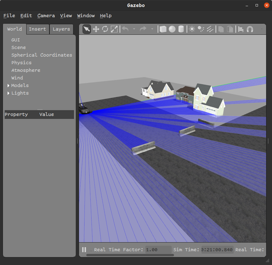
roslaunch catvehicle catvehicle_neighborhood.launch
and the following in the second terminal:
gzclient
gzclient should open a Gazebo window that should look like the one shown in Figure 1.
3 CAT Vehicle APIs for Vehicle Control Applications
While this section is not a tutorial on how to use ROS, it is necessary to understand a few basic things about ROS that can help create some simple control applications. we explain the basics using what is provided through the CAT Vehicle package.
3.1 The Launch File
ROS provides a methodology to execute a specialized program called ROS nodes through launch files. ROS nodes do some meaningful tasks (such as executing a control law) and publish messages on a named topic or subscribe to some other messages through a named topic. At the same time, some other ROS nodes can subscribe to messages being published through topics. Topics are like slots and nodes put messages on those slots – some other node can read those slots to get messages.
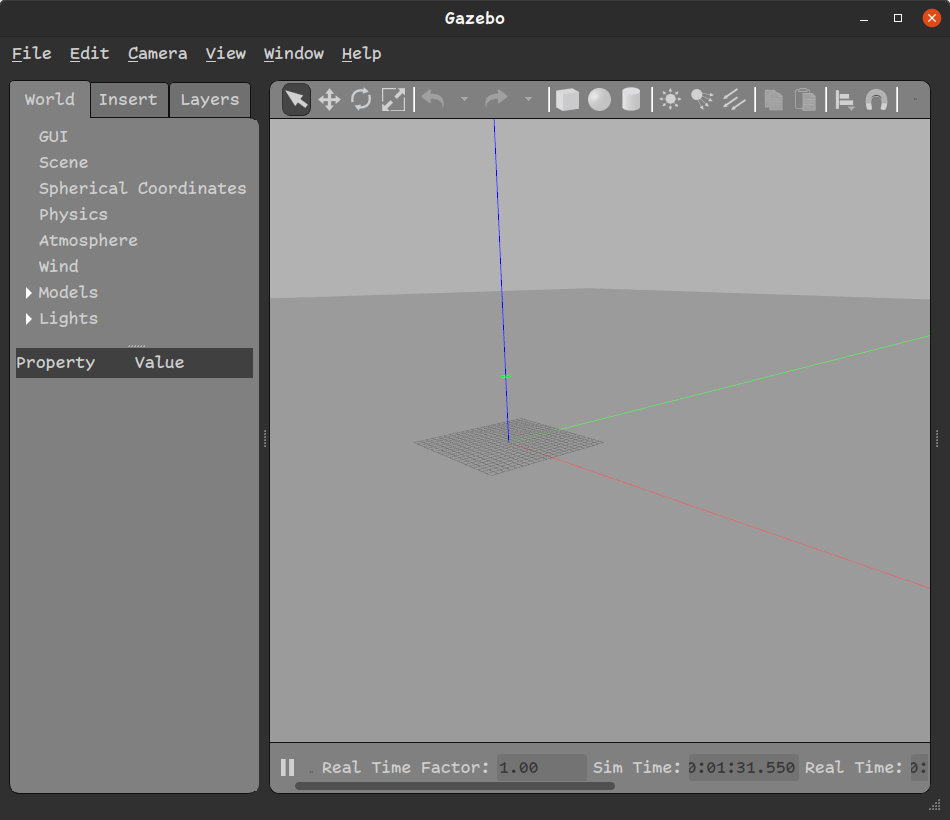
Launch files have an extension .launch and they are generally in the launch directory of a ROS package. In the case of the CAT Vehicle package, consider the launch file catvehicle_empty.launch. It can be used to create a simulation by typing the following in a terminal
roslaunch catvehicle catvehicle_empty.launch
To see the visual, we type the following in another terminal:
gzclient
The above command launches a window in the Gazebo program showing a virtual world with a ground plane and the center coordinates as shown in Figure 2.
3.2 Spawning a Vehicle
Spawning a vehicle in the virtual world is done using the catvehicle_spawn.launch file in another terminal.
roslaunch catvehicle catvehicle_spawn.launch
By default, it creates a vehicle at the origin with the name catvehicle. The launch file provides several command line arguments that can be revealed by pressing the tab a couple of times after typing roslaunch catvehicle catvehicle_spawn.launch in the terminal. We have the following command line arguments:
-
•
camera_left: to enable the left camera mounted on the car.
-
•
camera_right: to enable the right camera mounted on the car.
-
•
laser_sensor: to enable front 2-D Lidar sensor.
-
•
obstaclestopper: to enable a custom control node that prevents collision.
-
•
pitch: specify the pitch in radian.
-
•
robot: the name of the car. you must specify a unique name when spawning multiple cars in the simulation.
-
•
roll: specify the roll in radian.
-
•
triclops: enable front-mounted camera on the car.
-
•
updateRate: specify the update rate of speed of the car published.
-
•
velodyne_points: enable 3D Velodyne Lidar sensor.
-
•
X: specify the X coordinate of the car.
-
•
Y: specify the Y coordinate of the car.
-
•
yaw: specify the yaw of the car in radian.
-
•
Z: specify the Z coordinate of the car.
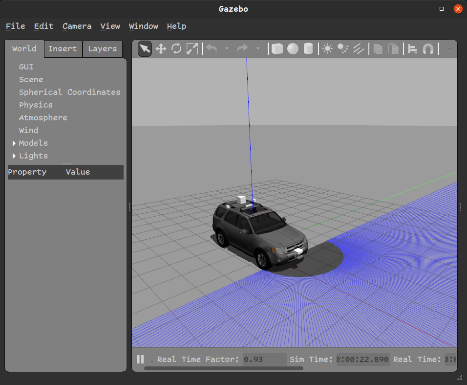
With some of the most essential options, we can spawn a car with the following command-line arguments:
roslaunch catvehicle spawn.launch robot:=ego X:=0.0 laser_sensor:=true
The above command spawns a car at the center with the name ego and a front 2D Lidar sensor enabled. Figure 3 displays the outcome.
3.3 Important ROStopics in the CAT Vehicle package
To develop a control application, we will need to know about some important ROS topics. A full list of topics can be obtained by typing rostopic list and anything that starts with /ego are topics associated with the above car we spawned. /ego/vel is where we get the current driving speed of the car on its linear.x component. Note that each topic has a message type that is equivalent to a C++ structure. You can see the message types of each topic in the output of the rostopic list. Interested readers can learn more about ROS messages at http://wiki.ros.org/msg. The relative speed of any car being followed by a car directly in its front can be found on the linear.z component of /ego/rel_vel. It will be zero if there is no car in the front. Headway distance of the leader car in front of the ego car is obtained on the topic /ego/lead_dist on the data component. A control command to the car can be sent on the topic /ego/cmd_vel where you can specify speed on the linear.x component and steering angle on the angular.z component.
4 Controller Modeling Example
For controller modeling, we take the approach of model-based design using Simulink software which is a part of Mathworks’ MATLAB. Simulink provides a library of blocks for specific purposes. One such blocks are ROS toolbox that can be used for creating controller models.
4.1 Modeling in Simulink
Open MATLAB, in the MATLAB command prompt, type simulink. Select “Create Model” in the Blank Model option. In the empty model workspace, you can see Library Browser where you can choose, drag-and-drop blocks to perform certain tasks. We are interested in blocks from ROS Toolbox. Note that my example is built in MATLAB 2022b. We are interested in a naive velocity control shown in Equation 1 which we arbitrarily came up with. This control law is merely for following a vehicle in its front if there is one.
| (1) |
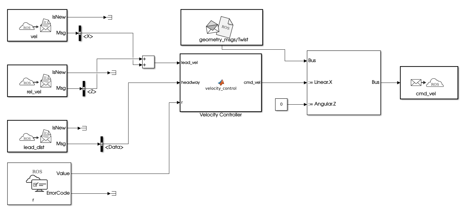
In Equation (1), is the desired velocity for the ego vehicle (The ego vehicle is the one we are interested in controlling). is the speed of the vehicle or an object directly in the range of the ego vehicle’s front LiDAR sensor. is reconstructed from LiDAR data by differentiating headway (that is available on the /ego/lead_dist topic) and adding to the ego’s current velocity (obtained from the topic /ego/vel). Differentiated relative velocity is published on /ego/rel_veltopic. is published on the topic /ego/cmd_vel. Note that /ego/cmd_vel and /ego/vel are different because a vehicle has dynamics so it won’t exactly be driving with what it is commanded to do so. We have a hidden transfer function to represent the vehicle dynamics but we don’t model it separately. It is done by rigid body dynamics implemented in the CAT Vehicle package.
A full model of Equation (1) in Simulink is shown in Figure 4 where the Equation is contained in MATLAB function block.
4.2 Settings for the model
In the Simulink Simulation tab, we set the stop time of the simulation to be inf. Now, we specify ROS-related parameters in the Modeling tab -> Model Settings to generate a ROS node. In Model Settings, we use the following settings:
-
1.
Solver -> Type: Fixed Step, Fixed-Step Size: 0.05 (which is in seconds)
-
2.
Hardware implementation-> Hardware Board: Robot Operating System, Target Hardware Resources-> Build Options: Build and Load, Catkin Workspace: ~/catvehicle_ws/ (or /home/<username>/catvehicle_ws/)
Then we press OK. We save the model as velocity_control.slx. The Simulink file used in this example can be downloaded from https://github.com/rahulbhadani/medium.com/blob/master/10-30-2022/velocity_control.slx.
4.3 Generating ROS node and corresponding launchfile from the Simulink model
To generate the ROS node, we type roscore in a terminal window, and then in the Simulink ROS tab, press Build & Load. It compiles the model and generates a C++ standalone ROS node in ~/catvehicle_ws/src. The first step in running the simulation is to create a launch file. We first create a new text file in an editor and copy the following code:
<?xml version="1.0" encoding="UTF-8"?>
<launch>
<arg name="robot" default="ego"/>
<arg name="r" default="20.0"/>
<param name="/$(arg robot)/r" type="double" value="$(arg r)"/>
<group ns="ego">
<node pkg="velocity_control" type="velocity_control"
name="velocity_control_node" output="screen"/>
</group>
</launch>
We save the text file as velocity_control.launch in the launch folder of the catvehicle package (which may be in the ~/catvehicle_ws/src/catvehicle/launch directory).
4.4 Simulation Setup
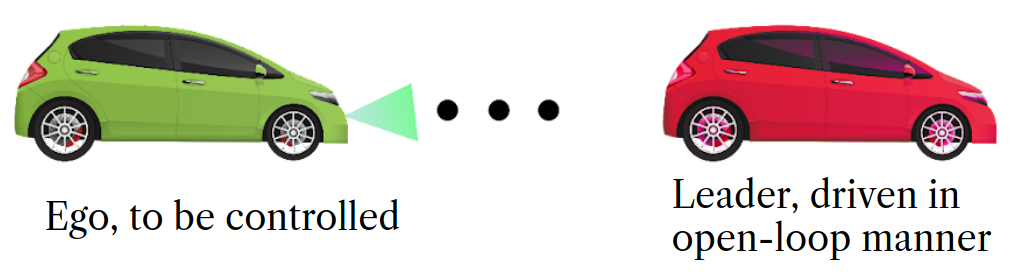
We consider a two-vehicle simulation where the first vehicle or the leader vehicle drives with an open loop trajectory specified from a data file. The data file can be downloaded from https://github.com/rahulbhadani/medium.com/releases/download/data/test_data.csv The leader vehicle control is executed using velinjector.launch. For the purpose of this tutorial, we save data in the home directory. A whole setup is illustrated in Figure 4.
4.5 Running the Simulation
To run the simulation with our velocity controller developed in the Simulink, we need to execute several roslaunch files in different terminal windows. To make things easier, we can use the bash script below which executes all roslaunch one by one.
#!/bin/bash
gnome-terminal -- roslaunch catvehicle catvehicle_empty.launch
sleep 5
gnome-terminal -- roslaunch catvehicle catvehicle_spawn.launch robot:=leader X:=30.0
sleep 5
gnome-terminal -- gzclient
sleep 5
gnome-terminal -- roslaunch catvehicle spawn.launch robot:=ego X:=0.0 laser_sensor:=true
sleep 5
velinjectfile="roslaunch catvehicle velinjector.launch
csvfile:=/home/ubuntu/test_data.csv input_type:=CSV
time_col:=Time vel_col:=speed robot:=leader str_angle:=0.0"
gnome-terminal -- $velinjectfile
sleep 5
gnome-terminal -- roslaunch catvehicle velocity_control.launch robot:=ego r:=2.5
sleep 5
gnome-terminal -- rosparam set /execute true
We save the above bash script as run_controller.sh and execute the following to run the simulation
chmod +x run_controller.sh
./run_controller.sh
The above command opens a series of terminal windows and executes all commands one by one.
To log the data in a .bag format, type rosbag record -a. The .bag file can be analyzed using the bagpy python package. How to use the bagpy package can be found at https://jmscslgroup.github.io/bagpy. To terminate the simulation, we press Ctrl-C in every terminal window that was opened through the bash script. To stop the rosbag recording, we also need to press Ctrl-C.
5 Conclusion and Discussion
In this article, we have discussed how to use the CAT Vehicle ROS package and Simulink’s model-based design approach to prototype a vehicle control law and test it in the Simulation. The example presented in this article uses local data corresponding to the ego vehicle, however, a more complex control law that uses non-local data is also possible. Further other sensor information such as front and side-camera can be used for improving the decision-making ability of the velocity control. However, based on the current implementation of the simulator in the CAT Vehicle package, only a velocity control command is possible. If acceleration-based control law needs to be prototyped, one needs to take an indirect approach of adding an integrator block in Simulink to integrate the commanded acceleration to produce a velocity command.
References
- [1] Rahul Bhadani, Matthew Bunting, Benjamin Seibold, Raphael Stern, Shumo Cui, Jonathan Sprinkle, Benedetto Piccoli, and Daniel B Work. Real-time distance estimation and filtering of vehicle headways for smoothing of traffic waves. In Proceedings of the 10th ACM/IEEE International Conference on Cyber-Physical Systems, pages 280–290, 2019.
- [2] Rahul Bhadani, Jonathan Sprinkle, and Matthew Bunting. The CAT Vehicle Testbed: A Simulator with Hardware in the Loop for Autonomous Vehicle Applications. In Proceedings 2nd International Workshop on Safe Control of Autonomous Vehicles (SCAV 2018), Porto, Portugal, 10th April 2018, Electronic Proceedings in Theoretical Computer Science 269, volume 269, pages 32–47, 2018.
- [3] Rahul Kumar Bhadani, Benedetto Piccoli, Benjamin Seibold, Jonathan Sprinkle, and Daniel Work. Dissipation of emergent traffic waves in stop-and-go traffic using a supervisory controller. In 2018 IEEE Conference on Decision and Control (CDC), pages 3628–3633. IEEE, 2018.
- [4] Maria Laura Delle Monache, Thibault Liard, Anais Rat, Raphael Stern, Rahul Bhadani, Benjamin Seibold, Jonathan Sprinkle, Daniel B Work, and Benedetto Piccoli. Feedback control algorithms for the dissipation of traffic waves with autonomous vehicles. In Computational Intelligence and Optimization Methods for Control Engineering, pages 275–299. Springer, 2019.
- [5] Alexey Dosovitskiy, German Ros, Felipe Codevilla, Antonio Lopez, and Vladlen Koltun. Carla: An open urban driving simulator. In Conference on robot learning, pages 1–16. PMLR, 2017.
- [6] Yuchuan Du, Chenglong Liu, and Yishun Li. Velocity control strategies to improve automated vehicle driving comfort. IEEE Intelligent transportation systems magazine, 10(1):8–18, 2018.
- [7] Nathan Koenig and Andrew Howard. Design and use paradigms for gazebo, an open-source multi-robot simulator. In 2004 IEEE/RSJ International Conference on Intelligent Robots and Systems (IROS)(IEEE Cat. No. 04CH37566), volume 3, pages 2149–2154. IEEE, 2004.
- [8] Nathan Lichtle, Eugene Vinitsky, George Gunter, Akash Velu, and Alexandre M Bayen. Fuel consumption reduction of multi-lane road networks using decentralized mixed-autonomy control. In 2021 IEEE International Intelligent Transportation Systems Conference (ITSC), pages 2068–2073. IEEE, 2021.
- [9] Maria Michalowska and Mariusz Oglozinski. Autonomous vehicles and road safety. In International Conference on Transport Systems Telematics, pages 191–202. Springer, 2017.
- [10] Navid Mohajer, Saeid Nahavandi, Hamid Abdi, and Zoran Najdovski. Enhancing passenger comfort in autonomous vehicles through vehicle handling analysis and optimization. IEEE Intelligent Transportation Systems Magazine, 13(3):156–173, 2020.
- [11] Yanyan Qin, Hao Wang, and Bin Ran. Stability analysis of connected and automated vehicles to reduce fuel consumption and emissions. Journal of Transportation Engineering, Part A: Systems, 144(11):04018068, 2018.
- [12] Morgan Quigley, Ken Conley, Brian Gerkey, Josh Faust, Tully Foote, Jeremy Leibs, Rob Wheeler, Andrew Y Ng, et al. Ros: an open-source robot operating system. In ICRA workshop on open source software, volume 3, page 5. Kobe, Japan, 2009.
- [13] Shital Shah, Debadeepta Dey, Chris Lovett, and Ashish Kapoor. Airsim: High-fidelity visual and physical simulation for autonomous vehicles. In Field and service robotics, pages 621–635. Springer, 2018.
- [14] Raphael E Stern, Shumo Cui, Maria Laura Delle Monache, Rahul Bhadani, Matt Bunting, Miles Churchill, Nathaniel Hamilton, Hannah Pohlmann, Fangyu Wu, Benedetto Piccoli, et al. Dissipation of stop-and-go waves via control of autonomous vehicles: Field experiments. Transportation Research Part C: Emerging Technologies, 89:205–221, 2018.
- [15] Cathy Wu, Aboudy Kreidieh, Kanaad Parvate, Eugene Vinitsky, and Alexandre M Bayen. Flow: Architecture and benchmarking for reinforcement learning in traffic control. arXiv preprint arXiv:1710.05465, 10, 2017.
- [16] Ge Zhu, Yuche Chen, and Jiali Zheng. Modelling the acceptance of fully autonomous vehicles: a media-based perception and adoption model. Transportation research part F: traffic psychology and behaviour, 73:80–91, 2020.