Abstract
We consider the Casimir pressure between two metallic plates and calculate the four contributions to it determined by the propagating and evanescent waves and by the transverse magnetic and transverse electric polarizations of the electromagnetic field. The range of interplate separations is considered where nearly the whole pressure has its origin in the electromagnetic response of conduction electrons. In the Casimir physics, this response is described either by the dissipative Drude model resulting in contradictions with the measurement data or by the experimentally consistent but dissipationless plasma model. It is shown that the total transverse magnetic contribution to the Casimir pressure due to both the propagating and evanescent waves and the transverse electric contribution due to only the propagating waves, computed by means of the Drude model, correlate well with the corresponding results obtained using the plasma model. The conclusion is made that a disagreement between the theoretical predictions obtained using the Drude model and precision measurements of the Casimir force is not caused by the account of dissipation in itself, but arises from an incorrect description of the response of metals to the low-frequency transverse electric evanescent waves by this model. It is demonstrated that the Drude model has no supporting experimental evidence in the range of transverse electric evanescent waves, so that the above conclusion is consistent with all available information. The alternative test of the Drude model for the transverse electric evanescent waves suggested in the framework of classical electrodynamics is discussed.
keywords:
Casimir force; Lifshitz theory; Drude model; plasma mode; propagating waves; evanescent waves; transverse electric and transverse magnetic polarizations; dissipation of conduction electrons5 \issuenum4 \articlenumber062 \datereceived24 July 2023 \daterevised24 August 2023 \dateaccepted31 August 2023 \datepublished27 September 2023 \hreflinkhttps://doi.org/10.3390/physics5040062 \TitleCasimir Effect Invalidates the Drude Model for Transverse Electric Evanescent Waves \TitleCitationCasimir Effect Invalidates the Drude Model for Transverse Electric Evanescent Waves \AuthorGalina L. Klimchitskaya 1,2*\orcidA and Vladimir M. Mostepanenko 1,2,3\orcidB \AuthorNamesGalina L. Klimchitskaya, Vladimir M. Mostepanenko \AuthorCitationKlimchitskaya, G.L.; Mostepanenko, V.M. \corresCorrespondence: g.klimchitskaya@gmail.com
1 Introduction
The Casimir effect is the relativistic and quantum phenomenon which has attracted widespread attention in the 75 years since its prediction in 1948 1 . This effect is very popular owing to its unusual character. Casimir predicted that two parallel uncharged ideal metal planes at zero temperature attract each other with the force which depends only on the interplate separation and the fundamental constants and . In 1955, Lifshitz demonstrated 2 that the Casimir force falls into the general theory of dispersion forces, which act between any material bodies. From the point of view of the Lifshitz theory, both the van der Waals and and Casimir forces are the manifestations of a single dispersion force, but in different regions of separations and temperatures. The Lifshitz theory makes it possible to calculate the Casimir force between two thick material plates by using the response functions of plate materials to the electromagnetic field in the form of frequency-dependent dielectric permittivities.
The Casimir force is unique in being important for such diverse fields of physics as theory of elementary particles, gravitation and cosmology, quantum electrodynamics, condensed matter physics, atomic physics, and also for nanotechnology. As a result, a great number of papers was devoted to this subject during the last decades (see the lists of references in the monographs 3 ; 4 ; 5 ; 6 ; 7 ; 8 ; 9 ; 10 ; 11 ; 12 ). In doing so, much attention has been paid to precision measurements of the Casimir force.
The present stage in measuring the Casimir force started with an experiment 13 , which used the configuration of an Au-coated spherical lense of centimeter-size radius above an Au-coated plate. As was understood later, the presence of the so-called patch potentials 14 and surface imperfections 15 on the centimeter-size surfaces prevents from reaching the highly precise results in measuring the Casimir force. The highly accurate measurements were performed between a microscopic sphere and a plate by means of an atomic force microscope and a micromechanical torsional oscillator pioneered in 16 and 17 , respectively.
The many times repeated measurements of the Casimir force performed by means of a micromechanical torsional oscillator 18 ; 19 ; 20 ; 21 ; 22 ; 23 and an atomic force microscope 24 ; 25 ; 26 ; 27 ; 28 ; 29 ; 30 led to the unexpected result. It was found that the measurement data are in a very good agreement with theoretical predictions of the Lifshitz theory if the low-frequency response of metals to the electromagnetic field is described by the dissipationless plasma model. If the dissipative Drude model is used, which should describe the conduction electrons correctly, the theoretical predictions are excluded by the data with certainty 18 ; 19 ; 20 ; 21 ; 22 ; 23 ; 24 ; 25 ; 26 ; 27 ; 28 ; 29 ; 30 . Only in a single experiment 31 , the force values computed by means of the Drude model were confirmed, but the measurements were performed by means of a centimeter-size spherical lens. As a result, the theoretical uncertainty due to patch potentials removed by means of the fitting procedure exceeded the Casimir force value by an order of magnitude. Moreover, the surface imperfections, which are always present on lens surfaces, were not taken into account in this experiment 15 ; 31a .
The contradiction between theoretical predictions of the Lifshitz theory obtained using the apparently well-tested Drude model and measurements of the Casimir force is often named the Casimir puzzle 32 ; 33 ; 34 . A rich variety of approaches has been suggested in the literature in an effort to resolve it. One could mention an employment of the alternative sets of the optical data 35 ; 36 , modeling the patch effect 14 ; 31 ; 37 , a more accurate account of the surface roughness 38 ; 39 ; 40 , refined theory for the sphere-plate geometry 41 ; 42 ; 43 ; 44 ; 45 ; 46 etc. (see 11 ; 47 ; 48 ; 49 for a review).
Particular emphasis has been placed on the frequency region of the anomalous skin effect where the Drude dielectric function becomes inapplicable due to the spatial nonlocality 50 ; 51 ; 52 . It was found, however, that the corresponding correction to the Casimir force is too small and cannot explain the discrepancy between the measurement data and theory which uses the Drude model 50 .
The important step was made in 53 ; 54 where it was shown that
large thermal correction to the Casimir force predicted by the Drude
model arises from the transverse electric
(s-polarized) evanescent waves
with low frequencies. This result was obtained by analyzing the
frequency spectrum of the thermal correction along the real frequency
axis. The predicted large thermal correction to the Casimir force, which
distinguishes the Drude model from the plasma model and the model of an
ideal metal, was also interpreted as arising from the contribution of
eddy (Foucault) current modes 55 ; 56 .
Furthermore, it was shown that at separations exceeding the thermal length (i.e., above approximately 6 m at K) the contributions of the transverse electric propagating and evanescent waves to the total Casimir force calculated using the Drude model are equal in magnitude and cancel each other 57 . According to 58 , at large separations the contributions of the transverse magnetic (p-polarized) and transverse electric propagating waves are equal regardless of what dielectric model (Drude or plasma) is used in computations. As to the contribution of transverse magnetic evanescent waves, it is equal to zero for both the Drude and plasma models. Thus, at large separations, the difference in Casimir forces computed using the Drude and plasma models originates solely from the contribution of transerse electric evanescent waves.
In this paper, we investigate the contributions of both the transverse magnetic and transverse electric propagating and evanescent waves into the Casimir force per unit area (i.e., the Casimir pressure) for two parallel Au-coated plates in the experimentally relevant separation region from 0.5 to 4 m where the total force value, in the limits of measurement errors, is determined by the dielectric response of conduction electrons. The contributions of the transverse magnetic and transverse electric propagating and evanescent waves are calculated in the framework of the Lifshitz theory employing either the Drude or the plasma model. For this purpose, we combine the computational results obtained using the formalisms represented in terms of the pure imaginary and real frequencies.
It is shown that the contributions of the transverse magnetic waves to the total Casimir force computed using the Drude and plasma models nearly coincide. The contributions of the transverse electric propagating waves to the Casimir force computed using the Drude and plasma models also turned out to be rather close. As a result, the relatively big difference between the theoretical predictions for the total Casimir force made by means of the Drude and plasma models over the experimentally relevant range of separations comes from different contributions of the transverse electric evanescent waves. Taking into account that this big difference is experimentally excluded by the measurement data of numerous experiments mentioned above, the conclusion is made that the Drude model breaks down in the region of transverse electric evanescent waves. We demonstrate that this conclusion is not in conflict with numerous experimental tests of the Drude model. The obtained results are discussed in connection with the role of dissipation of conduction electrons in the Lifshitz theory.
The paper is organized as follows. In Section 2, we briefly present the formalisms of the Lifshitz theory in terms of either pure imaginary or real frequencies separating the contributions of the transverse magnetic and transverse electric polarizations and the propagating and evanescent waves. Section 3 is devoted to computations of the Casimir pressure between metallic plates using the Drude and the plasma models and the optical data for the complex index of refraction. In Section 4, the contributions of the propagating and evanescent waves are studied for the transverse magnetic and transverse electric polarizations using the Drude and plasma models. Section 5 discusses the failure of the Drude model for the transverse electric evanescent waves, the role of dissipation of conduction electrons, and the possibilities of alternative tests disconnected with the Casimir effect. Section 6 contains our conclusions.
2 Formalisms of the Lifshitz Theory in Terms of Real or Pure Imaginary Frequencies
We consider the Casimir force per unit area of two similar metallic plates described by the dielectric permittivity , i.e., the Casimir pressure. The plates are at temperature in thermal equilibrium with the environment and are separated by a distance . Then, the Casimir pressure can be expressed by the Lifshitz formula 2 . This formula can be presented in terms of real frequencies or pure imaginary (Matsubara) frequencies.
In terms of real frequencies, the Casimir pressure is given by the sum of contributions from the propagating and evanescent waves each of which, in its turn, consists of two components determined by the transverse magnetic (TM) and transverse electric (TE) polarizations
| (1) |
Here 11
| (2) |
and
| (3) |
In these equations, the following notations are introduced. The Boltzmann constant is , the magnitude of the wave vector projection on the plane of plates is , the reflection coefficients for the TM and TE polarizations are
| (4) |
and
| (5) |
Note that by solving the Maxwell equations with the continuity boundary conditions on the surfaces of metallic plates, one determines the Casimir energy via the sum of discrete photon eigenfrequencies (or the cavity modes or the wave guide modes, as they are often referred to 58a ). The continuous frequencies in Equation (3) appear after performing a summation over the discrete frequencies by means of the argument principle.
As is seen from (2), for the propagating waves in accordance to the mass-shell equation in free space. The quantity in this case is pure imaginary and the integrand in (2) contains the rapidly oscillating function that plagues numerical computations. For the evanescent waves in (3), the mass-shell equation is violated , but the quantity takes real values making accessible computations of by means of (3).
One can conclude that equations (1)–(3) are not convenient for computations of the total Casimir pressure (1), but the contributions from the evanescent waves can be computed by (3).
In terms of the pure imaginary Matsubara frequencies, with , the Casimir pressure is expressed by the most commonly used Lifshitz formula
| (6) |
where 11
| (7) |
The prime on the summation sign in (7) divides the terms with by 2, and the reflection coefficients are again defined by (4) with , so that in line with (5)
| (8) |
where
Equation (7) is convenient for numerical computations of , but it alone does not allow computation of the contributions from the propagating and evanescent waves. In fact all the four components of the Casimir pressure on the right-hand side of (1) can be found by the combined application of the Lifshitz formulas (3) in terms of real frequencies and (7) in terms of the Matsubara frequencies. For this purpose, it is necessary to compute the contributions by (3) and the total Casimir pressures by (7). Then, the remaining contributions are found from
| (9) |
The numerical computations of all four components of the total Casimir pressure between metallic plates using different dielectric functions of a metal are presented in the next sections.
3 Calculation of the Casimir Pressure Between Metalic Plates Using the Drude and Plasma Models
It has been known that the dielectric response of metals to the electromagnetic field is determined by the combined action of conduction and bound (core) electrons. In doing so, the corresponding contributions to the dielectric permittivity make a substantially different impact on the Casimir pressure 11 . At short separations between the plates (up to tens of nanometers), the major contribution to the Casimir pressure is given by the region of very high frequencies, where is fully determined by the core electrons. In the transition region (from tens to hundreds of nanometers), both the conduction and core electrons determine the value of at the frequencies contributing to the Casimir pressure. Finally, at separations exceeding several hundreds of nanometers, only the conduction electrons determine the dielectric response of metals at the characteristic (low) frequencies.
Taking into account that the problem of disagreement between experiment and theory discussed in Section 1 arises exclusively due to the role of conduction electrons, it is appropriate to consider the separation region where the role of core electrons in computations of the Casimir pressure is negligibly small. In this section, the sought for region is found for two Au plates at room temperature K (the same results are valid for the plates made of any material coated with an Au layer of thickness exceeding several tens of nanometers 11 ).
As discussed in Section 1, the conduction electrons are commonly described by the dielectric permittivity of the dissipative Drude model
| (10) |
where, for Au, the plasma frequency rad/s and the relaxation parameter at K takes the value rad/s 59 .
The dielectric permittivity of the plasma model, which disregards the dissipation properties of conduction electrons, is obtained from (10) by putting
| (11) |
This model is physically applicable only at high frequencies in the region of infrared optics. However, as mentioned in Section 1, the theoretical results obtained using the plasma model at low frequencies, including the zero frequency, agree with measurements of the Casimir force. As to the Drude model, which is physically applicable at low frequencies, it leads to contradictions between theoretical predictions of the Lifshitz theory and the measurement data.
As it was discussed many times in the literature starting from 60 ; 61 , the important formal difference between the dielectric permittivities (10) and (11) is that they lead to radically different values of the TE reflection coefficient defined in (4) at zero frequency
| (12) |
It immediately follows that at large separations, where the Casimir pressure is determined by the terms of (7) with ,
| (13) |
where is the Riemann zeta function. This is one half of the result obtained at large separations for the ideal metal planes.
For the plasma model, the case of ideal metal planes is obtained in the limit where
| (14) |
and the terms of (7) with are
| (15) |
These are the same results as are obtained for the ideal metal planes. The quantities (13) and (15) do not depend on . They represent the classical limit of the Casimir pressure at large separations found using the Drude and plasma models, respectively.
To determine the region of separations, where the dielectric permittivities of the Drude and plasma models (10) and (11) determine nearly the total Casimir pressure, we, first, compute the values of and and then compare the obtained results with the Casimir pressures computed using the available optical data of Au extrapolated down to zero frequency by means of the Drude or plasma models.
Numerical computations of the Casimir pressure at K were performed by (6) and (7) with the reflection coefficients (4) and the dielectric permittivities (10) and (11). The computational results for the ratios of obtained pressures to defined in (13) are presented in Figure 1 as a function of separation by the top and bottom solid lines computed using the plasma and Drude models, respectively. The two dashed lines indicate the corresponding limiting values of the pressure ratios at large separations.
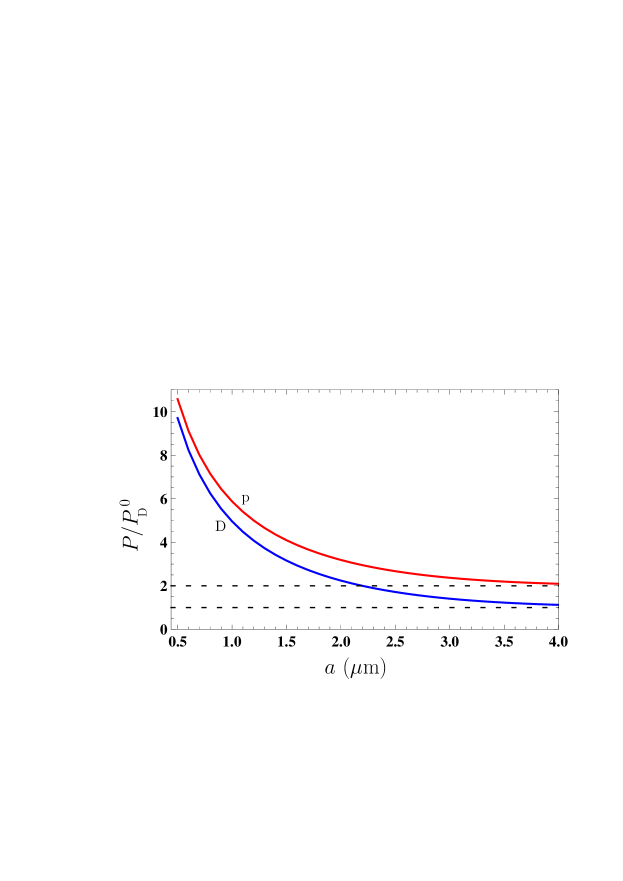
As is seen in Figure 1, the theoretical predictions obtained using the plasma and Drude models differ by the factors of 1.09 at m, 1.2 at m, and 1.86 at m. In the limit of large separations (classical limit) the difference is by the factor of 2.
Now we determine the error in Casimir pressures made by omitting the contribution of core electrons in the dielectric permittivity. For this purpose, we find the dielectric permittivity of Au along the imaginary frequency axis by means of the Kramers-Kronig relation where the imaginary part of this permittivity is given by the tabulated optical data of Au 59 extrapolated down to zero frequency by means of the plasma or the Drude model (see, e.g., 11 ; 47 for details). Then the Casimir pressure is again computed by (4), (6) and (7).
The relative deviation between the Casimir pressures obtained using the simple Drude and plasma models and using the optical data taking into account the core electrons can be characterized by the quantity
| (16) |
In Figure 2, the computational results for are shown as a function of separation by the top and bottom lines computed using the Drude and plasma models and corresponding extrapolations of the optical data, respectively. In the inset, the region of separations from 2 to m, where the two lines are partially overlapping, is shown on an enlarged scale for better visualization.
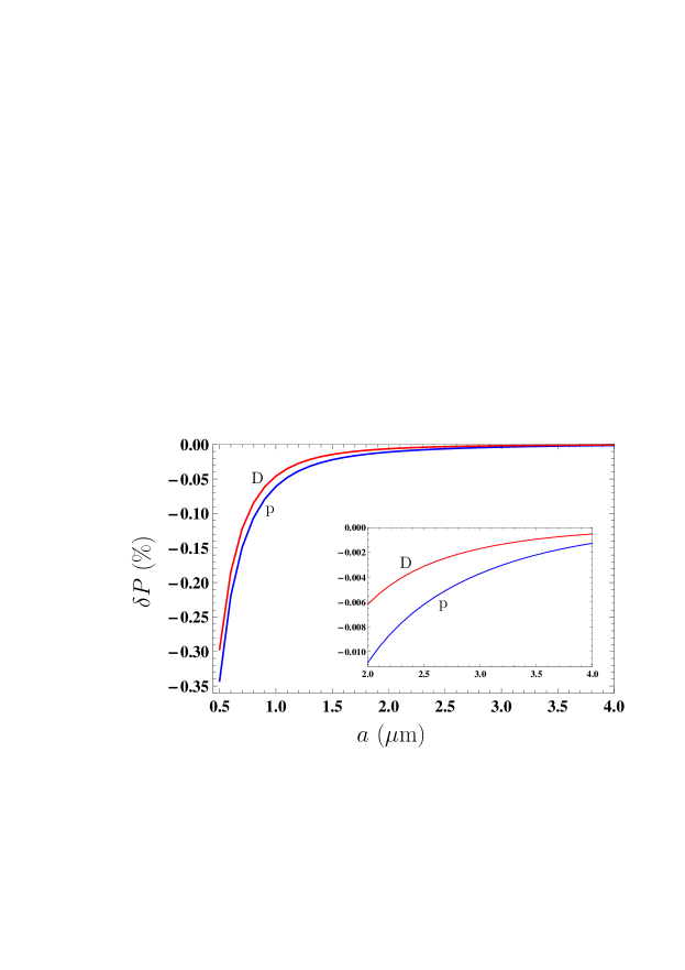
As is seen from Figure 2, at m the simple Drude and plasma models reproduce the Casimir pressure computed with due regard for core electrons with the relative errors less than 0.3% and 0.35%, respectively. These errors quickly decrease with increasing separation. Thus, at m they are below 0.05% and 0.052%, respectively.
Note that in the separation region above m the already performed precision determinations of the effective Casimir pressure between two parallel plates by measuring the force gradient in the sphere-plate geometry 18 ; 19 ; 20 ; 21 ; 22 ; 24 ; 25 ; 26 ; 27 ; 28 ; 29 ; 30 reliably distinguish between the top and bottom lines in Figure 1 in favor of the former at m. However, at m the same experiments cannot discriminate between the theoretical predictions made by means of only the simple Drude or plasma model and taking into account the core electrons. As an example, the total experimental error in measuring the Casimir pressure determined at the 67% confidence level is % at m 20 ; 21 and % at m 29 ; 30 (by measuring the Casimir force in the sphere-plate geometry, the theoretical description using the Drude model was excluded at all separations m 23 ).
4 Comparison Studies of Contributions from the Propagating and Evanescent Waves
Now we are in a position to find all the four contributions to the Casimir pressure (1) when using the simple Drude and plasma models and determine which of them is responsible for a disagreement between experiment and theory. In accordance with the results of Section 3, this should be done at separations between the plates exceeding m where the dielectric permittivities of the simple Drude and plasma models contribute nearly total value of the pressure. There is no point also in considering too large separations because the experimental situation there is uncertain. We begin with contribution of the TM polarized waves to the Casimir pressure.
4.1 Transverse Magnetic Polarization
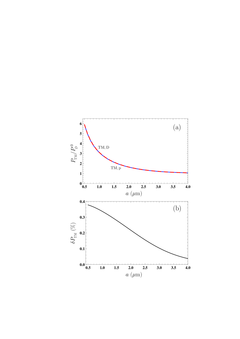
The contribution of the TM polarized waves, , is calculated by (7) where the reflection coefficient is given by the first equality in (4) taken at . Depending on whether we use the Drude (10) or the plasma (11) model of the dielectric permittivity, we obtain either or .
The computational results for normalized to at K are shown in Figure 3(a) as a function of separation by the solid and dashed lines computed using the Drude and plasma models, respectively. As can be seen in this figure, the solid and dashed lines coincide very closely.
In order to understand the measure of agreement between the theoretical predictions of the Lifshitz theory using the Drude and plasma models we consider the relative deviation
| (17) |
In Figure 3(b), the computational results for at K are shown by the solid line as a function of separation. As is seen in this figure, the relative deviation between the predictions obtained using these models decreases from approximately 0.38% at m to 0.04% at m. Remembering that the Drude model takes into account the dissipation processes, which are fully disregarded by the plasma model, one can conclude that the transverse magnetic contribution to the Casimir pressure between metallic plates is scarcely affected by the dissipation of conduction electrons. It becomes clear also that the impact of dissipation in different contributions to should be somehow compensated (see below).
Let us now determine the contributions of propagating and evanescent waves to when using the Drude and plasma models in computations. The contribution of evanescent waves is found by (3) with the reflection coefficient defined in (4), whereas the contribution of propagating waves can be obtained by (9), where the total TM contribution to the Casimir pressure is already computed [see Figure 3(a)].
First of all, it is evident from (3) that
| (18) |
This is because the dielectric permittivity of the plasma model (11) and, thus, the reflection coefficient in (4) are the real functions for evanescent waves.
Then, from (9) one concludes that
| (19) |
where is already shown by the red dashed line in Figure 3(a).
For the Drude model, the computations of are again performed by (3) with the reflection coefficient defined in (4) and the dielectric permittivity (10). The quantity is obtained from (9) where the already computed is shown by the solid line in Figure 3(a).
Figure 4 shows the computational results for and at K by the top short-dashed and bottom long-dashed lines as a function of separation. Both these lines are blue. For comparison purposes, in Figure 4 we also reproduce from Figure 3(a) the blue solid line and the overlapping with it red dashed line demonstrating the separation dependence of and , respectively (the latter also depicts the behavior of ).
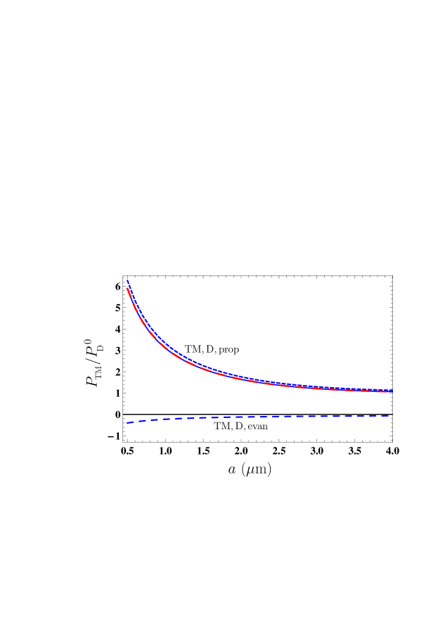
From Figure 4 it is seen that, although the quantities and are almost equal, their constituent parts due to the propagating and evanescent waves are different. For the plasma model, is determined entirely by the propagating waves, whereas for the Drude model the contribution of to is partially compensated by which is of the opposite sign, i.e., corresponds to the Casimir repulsion. This explains why there is no eventual impact of dissipation on , even though the Drude model is dissipative.
4.2 Transverse Electric Polarization
We calculate the contribution of the transverse electric polarization, , to the Casimir pressure by (7) with the reflection coefficient from (4) using the dielectric permittivities of the Drude model (10) and the plasma model (11). In Figure 5, the computational results for and normalized to at K are shown as a function of separation by the lower (blue) and upper (red) solid lines for the Drude and plasma models, respectively.
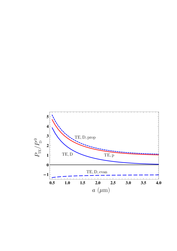
From Figure 5 it is seen that the lower and upper solid lines differ considerably. Keeping in mind that, according to the results of Section 4.1, and are equal with a high degree of accuracy, it becomes clear that this difference completely determines the discrepancy between the total Casimir pressures computed using the Drude and plasma models, and . The question arises what is the physical origin of this discrepancy.
To answer this question, we compute the quantities and by (3). As to the latter, it is evident that
| (20) |
because the dielectric permittivity of the plasma model (11) and the reflection coefficient from (4) are the real functions in the region of evanescent waves.
Taking into account (9), we also find that
| (21) |
i.e., that for the plasma model the total Casimir pressure determined by the transverse electric polarization is equal to the contribution of TE-polarized propagating waves. This is the same as was proven above for the TM polarization. Thus, is given by the upper solid line in Figure 5(a) already drawn for .
The computational results for obtained by (3), (4) and (10) at K are shown as a function of separation in Figure 5 by the bottom long-dashed line. As to the computational results for , they are found from (9) and shown by the top short-dashed line in Figure 5 as a function of separation.
All contributions to are now computed using both models of the dielectric response of Au and it is possible to analyze the role of each of them. First of all, from Figure 5 it is seen that the deviation between and shown by the top short-dashed line and the upper solid line, respectively (we recall that the latter line also shows ), is reasonably small and cannot be responsible for a much larger discrepancy between and . The latter is equal to the discrepancy between and shown by the two solid lines. In fact, the deviation between and demonstrates the impact of dissipation of conduction electrons on the TE contribution to the Casimir pressure, which is taken into account by the Drude model and disregarded by the plasma one. It is significant that this impact carried out through the TE propagating waves is not in contradiction with the experimental data on measuring the Casimir force.
A completely different type of situation occurs for shown by the bottom long-dashed line in Figure 5. The magnitude of is much larger than , and this leads to a significant deviation between and resulting ultimately in a contradiction between the measurement data and theoretical predictions of the Lifshitz theory obtained using the Drude model.
For better understanding of this situation, we should take into account that the Drude model has a wealth of alternative experimental confirmations in the area of propagating waves with any polarization, as well as for the transverse magnetic evanescent waves, but lacks of confirmation for the transverse electric evanescent waves (see a discussion of experimental situation in the next section). On this basis one can conclude that experiments on measuring the Casimir force between metallic test bodies invalidate the dielectric permittivity of the Drude model in the area of transverse electric evanescent waves. It is apparent that the alternative experimental confirmations of such a conclusion are highly desirable (see the next section).
5 Discussion: Failure of the Drude Model for Transverse Electric Evanescent Waves, the Role of Dissipation, and Possibilities of Alternative Tests
As discussed in Section 1, the theoretical predictions of the fundamental Lifshitz theory are in conflict with the measurement data of many precision experiments of Casimir physics if the dielectric response of conduction electrons is described by the dissipative Drude model. However, by disregarding the dissipation properties of conduction electrons, i.e., by using the plasma model, one can bring the measurement data in agreement with the theoretical predictions. This situation is unacceptable because the dissipation of conduction electrons at low frequencies is the much studied and confirmed by many experiments physical effect.
According to the results presented above, an account of dissipation by means of the Drude model in the transverse magnetic contribution to the Casimir pressure leads to the same results as are obtained using the dissipationless plasma model. This is because the dissipation-induced terms in the Casimir pressure arising from the evanescent and propagating waves cancel each other. The dissipation-induced term in the contribution to the Casimir pressure from the transverse electric propagating waves is found to be reasonably small and does not bring the theoretical predictions found using the Drude model in contradiction with the measurement data.
The performed computations show that the roots of contradiction are not in the account of dissipation in itself, but in how the Drude model describes the response of metals to the low-frequency transverse electric evanescent waves. These computations compared with the measurement data lead us to conclude that the theoretical description of the electromagnetic response of metals to the transverse electric evanescent waves given by the Drude model is in error. In this context, it is necessary to discuss what are the alternative experimental evidences about the validity of the Drude model other than the Casimir effect.
In the area of both the transverse magnetic and transverse electric propagating waves there is an abundance of experimental confirmations of the Drude model in physics, electrotechnics, and even in the day-to-day life, so that it makes no sense to discuss them. However, direct measurement of the reflection coefficients of a metal in the case of evanescent waves presents difficulties because all commonly used methods (ellipsometry, for instance) are adapted for the propagating waves.
Great interest to the evanescent waves during the last decades is connected with the fact that they made it possible to surmount the optical diffraction limit 62 . Thus, the physics of plasmons polaritons gives the possibility to obtain the great deal of evidence about the reflection of evanescent waves on metallic surfaces, but only for the transverse magnetic polarization 63 . The reflectivity properties of weakly evanescent waves (for which is only just above ) can be examined by means of the total internal reflection and frustrated total internal reflection 64 ; 65 ; 66 . The widely used in various technological applications near-field optical microscopy is reasonably sensitive to only the transverse magnetic evanescent waves 67 ; 67a (see also the discussion in 58 for more details).
The information provided above allows to conclude that the failure of the Drude model demonstrated by experiments on measuring the Casimir force does not contradict to all the available experimental evidences in favor of this model which are irrelevant to the area of transverse electric evanescent waves.
Despite the fact that there are many experiments mentioned above, which demonstrate the failure of the Drude model resulting from the region of transverse electric evanescent waves, it would be highly desirable to perform one more independent test disconnected with the Casimir effect. Recently such an alternative test in the field of classical electrodynamics was proposed in 58 ; 68 . It was shown that the lateral components of magnetic field of an oscillating magnetic dipole spaced in the proximity of metallic plate are determined by solely the transverse electric evanescent waves. According to the results of 58 ; 68 , by choosing the suitable dipole frequency and using either the Drude or the plasma model for the dielectric permittivity of metallic plate, the lateral components of the dipole field are varied by up to several orders of magnitide depending on the model used. Thus, by measuring these components for some fixed dipole parameters, it is possible to reliably conclude whether the Drude model describes correctly the response of plate metal to the transverse electric evanescent waves.
As an example, in 58 ; 68 the magnetic dipole of 1 mm size with the dipole moment of oscillating with the frequency of 100 rad/s at 1 cm height above the Cu plate was considered. Small dipoles of such kind are manufactured in the form of coils containing of about 10 turns 69 ; 70 ; 71 . In this case, the lateral component of the dipole magnetic field at the same height of 1 cm above the plate computed using the Drude model was found to be T 58 ; 68 . If the plasma model is used in computations, the larger by a factor of 10 magnetic field is obtained 58 ; 68 . Keeping in mind that the current resolution limit in measurements of weak magnetic fields is of about T 72 ; 73 ; 74 , the proposed alternative test of the Drude model in the region of transverse electric evanescent waves seems quite feasible.
Finally, if it is confirmed that the Drude model is really invalid in the region of low-frequency transverse electric evanescent waves, the question arises on how it could be corrected. Recently the modifications of the Drude model at low frequencies caused by the spatial dispersion were again considered 75 ; 76 in connection with the problems of Casimir physics. The suggested modifications, however, are incapable to bring the theoretical predictions in agreement with the measurement data for the Casimir force. The phenomenological spatially nonlocal alterations in the Drude model, which bring the theoretical predictions in agreement with all performed experiments on measuring the Casimir force, were suggested in 77 ; 78 ; 79 , but they are still lacking of fundamental theoretical justification. Thus, the proper form of the response function of metals to the transverse electric evanescent waves remains to be found.
6 Conclusions
To conclude, in this paper we have performed the comparison studies of four contributions to the Casimir pressure between metallic plates caused by the transverse magnetic and transverse electric polarizations of the electromagnetic field and by the propagating and evanescent waves. The region of separations was determined where the major contribution to the pressure is given by the electromagnetic response of free electrons described by the dissipative Drude model or the experimentally consistent but dissipationless plasma model used in comparisons between experiment and theory.
According to our results, the transverse magnetic contributions to the Casimir pressure computed by using the Drude or plasma models are equal to a high degree of accuracy. In so doing, if the Drude model is used, the relatively small contribution from the evanescent waves (which is equal to zero when using the plasma model) is canceled by an excessive contribution from the propagating waves. Thus, the use of the Drude model for computation of the Casimir pressure determined by the transverse electric polarization does not lead to contradictions between experiment and theory.
It was shown also that the transverse electric contribution to the Casimir pressure caused by the propagating waves, which is computed by using the Drude model, deviates reasonably small from the transverse electric contribution computed using the plasma model (the latter is again determined by the propagating waves alone). This deviation is due to the dissipation processes of propagating waves taken into account by the Drude model. It cannot explain a discrepancy between the theoretical predictions obtained using the Drude model and the measurement data because of its smallness.
Next, it was found that the experimental inconsistency of the Drude model is determined by the relatively large contribution of the transverse electric evanescent waves. This leads to a conclusion that the response of metals to the transverse electric evanescent waves is described by the Drude model incorrectly. In such a manner, the reason why the Lifshitz theory using the Drude model is experimentally inconsistent is not that it takes into account dissipation of free electrons, as opposed to the plasma model, but that it takes it into account incorrectly in the region of the transverse electric evanescent waves.
The presented analysis of experimental tests of the Drude model demonstrates that it is lacking experimental confirmation in this important region of the wave vectors and frequencies. Therefore, the recently proposed alternative test of the Drude model as a response function to the transverse electric evanescent waves should shed new light on the problem of disagreement between theoretical predictions of the Lifshitz theory and the measurement data.
G.L.K. was partially funded by the Ministry of Science and Higher Education of Russian Federation ("The World-Class Research Center: Advanced Digital Technologies", contract No. 075-15-2022-311 dated April 20, 2022). The research of V.M.M. was partially carried out in accordance with the Strategic Academic Leadership Program "Priority 2030" of the Kazan Federal University.
References
References
- (1) Casimir, H.B.G. On the attraction between two perfectly conducting plates. Proc. Kon. Ned. Akad. Wet. B 1948, 51, 793–795.
- (2) Lifshitz, E.M. The theory of molecular attractive forces between solids. Zh. Eksp. Teor. Fiz. 1955, 29, 94–110; Translated: Sov. Phys. JETP 1956, 2, 73–83.
- (3) Mahanty, J.; Ninham, B.W. Dispersion Forces; Academic Press: London, UK, 1976.
- (4) Israelachvili, J. Intermolecular and Surface Forces; Academic Press: San Diego, USA, 1992.
- (5) Milonni, P.W. The Quantum Vacuum. An Introduction to Quantum Electrodynamics; Academic Press: San Diego, CA, USA, 1994.
- (6) Mostepanenko, V.M.; Trunov, N.N. The Casimir Effect and Its Applications; Clarendon Press: Oxford, UK, 1997.
- (7) Milton, K.A. The Casimir Effect: Physical Manifestations of Zero-Point Energy; World Scientific: Singapore, 2001.
- (8) Parsegian, V.A. Van der Waals Forces: A Handbook for Biologists, Chemists, Engineers, and Physicists; Cambridge University Press: Cambridge, UK, 2005.
- (9) Buhmann, S.Y. Disperson Forces; Springer: Berlin, Germany, 2012; Volumes 1 and 2.
- (10) Langbein, D. Theory of Van der Waals Attraction; Springer-Verlag: Berlin and Heidelberg, Germany, 2013.
- (11) Bordag, M.; Klimchitskaya, G.L.; Mohideen, U.; Mostepanenko, V.M. Advances in the Casimir Effect; Oxford University Press: Oxford, UK, 2015.
- (12) Sernelius, B.E. Fundamentals of van der Waals and Casimir Interactions; Springer: New York, USA, 2018.
- (13) Lamoreaux, S.K. Demonstration of the Casimir Force in the 0.6 to 6 m Range. Phys. Rev. Lett. 1997, 78, 5–8.
- (14) Speake, C.C.; Trenkel, C. Forces between Conducting Surfaces due to Spatial Variations of Surface Potential. Phys. Rev. Lett. 2003, 90, 160403.
- (15) Bezerra, V.B.; Klimchitskaya, G.L.; Mohideen, U.; Mostepanenko, V.M.; Romero, C. Impact of surface imperfections on the Casimir force for lenses of centimeter-size curvature radii. Phys. Rev. B 2011, 83, 075417.
- (16) Mohideen, U.; Roy, A. Precision Measurement of the Casimir Force from 0.1 to 0.9 m. Phys. Rev. Lett. 1998, 81, 4549–4552.
- (17) Decca, R.S.; López, D.; Fischbach, E.; Krause, D.E. Measurement of the Casimir Force between Dissimilar Metals. Phys. Rev. Lett. 2003, 91, 050402.
- (18) Decca, R.S.; Fischbach, E.; Klimchitskaya, G.L.; Krause, D.E.; López, D.; Mostepanenko, V.M. Improved tests of extra-dimensional physics and thermal quantum field theory from new Casimir force measurements. Phys. Rev. D 2003, 68, 116003.
- (19) Decca, R.S.; López, D.; Fischbach, E.; Klimchitskaya, G.L.; Krause, D.E.; Mostepanenko, V.M. Precise comparison of theory and new experiment for the Casimir force leads to stronger constraints on thermal quantum effects and long-range interactions. Ann. Phys. (N.Y.) 2005, 318, 37–80.
- (20) Decca, R.S.; López, D.; Fischbach, E.; Klimchitskaya, G.L.; Krause, D.E.; Mostepanenko, V.M. Tests of new physics from precise measurements of the Casimir pressure between two gold-coated plates. Phys. Rev. D 2007, 75, 077101.
- (21) Decca, R.S.; López, D.; Fischbach, E.; Klimchitskaya, G.L.; Krause, D.E.; Mostepanenko, V.M. Novel constraints on light elementary particles and extra-dimensional physics from the Casimir effect. Eur. Phys. J. C 2007, 51, 963–975.
- (22) Bimonte, G.; López, D.; Decca, R.S. Isoelectronic determination of the thermal Casimir force. Phys. Rev. B 2016, 93, 184434.
- (23) Bimonte, G.; Spreng, B.; Maia Neto, P.A.; Ingold, G.-L.; Klimchitskaya, G.L.; Mostepanenko, V.M.; Decca, R.S. Measurement of the Casimir Force between 0.2 and m: Experimental Procedures and Comparison with Theory. Universe 2021, 7, 93.
- (24) Chang, C.-C.; Banishev, A.A.; Castillo-Garza, R.; Klimchitskaya, G.L.; Mostepanenko, V.M.; Mohideen, U. Gradient of the Casimir force between Au surfaces of a sphere and a plate measured using an atomic force microscope in a frequency-shift technique. Phys. Rev. B 2012, 85, 165443.
- (25) Banishev, A.A.; Chang, C.-C.; Klimchitskaya, G.L.; Mostepanenko, V.M.; Mohideen, U. Measurement of the gradient of the Casimir force between a nonmagnetic gold sphere and a magnetic nickel plate. Phys. Rev. B 2012, 85, 195422.
- (26) Banishev, A.A.; Klimchitskaya, G.L.; Mostepanenko, V.M.; Mohideen, U. Demonstration of the Casimir Force between Ferromagnetic Surfaces of a Ni-Coated Sphere and a Ni-Coated Plate. Phys. Rev. Lett. 2013, 110, 137401.
- (27) Banishev, A.A.; Klimchitskaya, G.L.; Mostepanenko, V.M.; Mohideen, U. Casimir interaction between two magnetic metals in comparison with nonmagnetic test bodies. Phys. Rev. B 2013, 88, 155410.
- (28) Xu, J.; Klimchitskaya, G.L.; Mostepanenko, V.M.; Mohideen, U. Reducing detrimental electrostatic effects in Casimir-force measurements and Casimir-force-based microdevices. Phys. Rev. A 2018, 97, 032501.
- (29) Liu, M.; Xu, J.; Klimchitskaya, G.L.; Mostepanenko, V.M.; Mohideen, U. Examining the Casimir puzzle with an upgraded AFM-based technique and advanced surface cleaning. Phys. Rev. B 2019, 100, 081406(R).
- (30) Liu, M.; Xu, J.; Klimchitskaya, G.L.; Mostepanenko, V.M.; Mohideen, U. Precision measurements of the gradient of the Casimir force between ultraclean metallic surfaces at larger separations. Phys. Rev. A 2019, 100, 052511.
- (31) Sushkov, A.O.; Kim, W.J.; Dalvit, D.A.R.; Lamoreaux, S.K. Observation of the thermal Casimir force, Nat. Physics 2011, 7, 230–233.
- (32) Klimchitskaya, G.L.; Bordag, M.; Mostepanenko, V.M. Comparison between experiment and theory for the thermal Casimir force. Int. J. Mod. Phys. A 2012, 27, 1260012.
- (33) Klimchitskaya, G.L.; Mostepanenko, V.M. Experiment and theory in the Casimir effect. Contemp. Phys. 2006, 47, 131–144.
- (34) Bimonte, G.; Emig, T.; Kardar, M.; Krüger, M. Nonequilibrium Fluctuational Quantum Electrodynamics: Heat Radiation, Heat Transfer, and Force. Ann. Rev. Condens. Matter Phys. 2017, 8, 119–143.
- (35) Milton, K.A.; Li, Y.; Kalauni, P.; Parashar, P.; Guérout, P.; Ingold, G.-L.; Lambrecht, A.; Reynaud, S. Negative Entropies in Casimir and Casimir-Polder Interactions. Fortschr. Phys. 2017, 65, 1600047.
- (36) Svetovoy, V.B.; van Zwol, P.J.; Palasantzas, G.; De Hosson, J.Th.M. Optical properties of gold films and the Casimir force. Phys. Rev. B 2008, 77, 035439.
- (37) Bimonte, G. Making precise predictions of the Casimir force between metallic plates via a weighted Kramers-Kronig transform. Phys. Rev. A 2011, 83, 042109.
- (38) Behunin, R.O.; Intravaia, F.; Dalvit, D.A.R.; Maia Neto, P.A.; Reynaud, S. Modeling electrostatic patch effects in Casimir force measurements. Phys. Rev. A 2012, 85, 012504.
- (39) van Zwol, P.J.; Palasantzas, G.; De Hosson, J.Th.M. Influence of random roughness on the Casimir force at small separations. Phys. Rev. B 2008, 77, 075412.
- (40) Broer, W.; Palasantzas, G.; Knoester, J.; Svetovoy, V.B. Roughness correction to the Casimir force at short separations: Contact distance and extreme value statistics. Phys. Rev. B 2012, 85, 155410.
- (41) Maia Neto, P.A.; Lambrecht, A.; Reynaud, S. Casimir effect with rough metallic mirrors. Phys. Rev. A 2005, 72, 012115.
- (42) Canaguier-Durand, A.; Maia Neto, P.A.; Cavero-Pelaez, I.; Lambrecht, A.; Reynaud, S. Casimir Interaction between Plane and Spherical Metallic Surfaces. Phys. Rev. Lett. 2009, 102, 230404.
- (43) Fosco, C.D.; Lombardo, F.C.; Mazzitelli, F.D. Proximity force approximation for the Casimir energy as a derivative expansion. Phys. Rev. D 2011, 84, 105031.
- (44) Bimonte, G.; Emig, T.; Jaffe, R.L.; Kardar, M. Casimir forces beyond the proximity force approximation. Europhys. Lett. 2012, 97, 50001.
- (45) Teo, L.P. Material dependence of Casimir interaction between a sphere and a plate: First analytic correction beyond proximity force approximation. Phys. Rev. D 2013, 88, 045019.
- (46) Bimonte, G. Going beyond PFA: A precise formula for the sphere-plate Casimir force. Europhys. Lett. 2017, 118, 20002.
- (47) Hartmann, M.; Ingold, G.-L.; Maia Neto, P.A. Plasma versus Drude Modeling of the Casimir Force: Beyond the Proximity Force Approximation. Phys. Rev. Lett. 2017, 119, 043901.
- (48) Klimchitskaya, G.L.; Mohideen, U.; Mostepanenko, V.M. The Casimir force between real materials: Experiment and theory. Rev. Mod. Phys. 2009, 81, 1827–1885.
- (49) Mostepanenko, V.M. Casimir Puzzle and Conundrum: Discovery and Search for Resolution. Universe 2021, 7, 84.
- (50) Klimchitskaya, G.L.; Mostepanenko, V.M. Current status of the problem of thermal Casimir force. Int. J. Mod. Phys. A 2022, 37, 2241002.
- (51) Esquivel, R.; Svetovoy, V.B. Correction to the Casimir force due to the anomalous skin effect. Phys. Rev. A 2004, 69, 062102.
- (52) Svetovoy, V.B.; Esquivel, R. Nonlocal impedances and the Casimir entropy at low temperatures. Phys. Rev. E 2005, 72, 036113.
- (53) Sernelius, Bo E. Effects of spatial dispersion on electromagnetic surface modes and on modes associated with a gap between two half spaces.
- (54) Torgerson, J.R.; Lamoreaux, S.K. Low-frequency character of the Casimir force between metallic films. Phys. Rev. E 2004, 70, 047102.
- (55) Bimonte, G. Comment on “Low-frequency character of the Casimir force between metallic films”. Phys. Rev. E 2006, 73, 048101.
- (56) Intravaia, F.; Henkel, C. Casimir Interaction from Magnetically Coupled Eddy Currents Phys. Rev. Lett. 2009, 103, 130405.
- (57) Intravaia, F.; Ellingsen, S.A.; Henkel, C. Casimir-Foucault interaction: Free energy and entropy at low temperature. Phys. Rev. A 2010, 82, 032504.
- (58) Svetovoy, V.B.; Esquivel, R. The Casimir free energy in high- and low-temperature limits. J. Phys. A Math. Gen. 2006, 39, 6777–6784.
- (59) Klimchitskaya, G.L.; Mostepanenko, V.M.; Svetovoy, V.B. Experimentum crusis for electromagnetic response of metals to evanescent waves and the Casimir puzzle. Universe 2022, 8, 574.
- (60) Bordag, M. The Casimir effect for thin plasma sheets and the role of the surface plasmons. J. Phys. A: Math. Gen. 2006, 39, 6173–6185.
- (61) Palik, E.D. (Ed.) Handbook of Optical Constants of Solids; Academic Press: New York, USA, 1985.
- (62) Boström, M.; Sernelius, Bo E. Thermal Effects on the Casimir Force in the 0.1-5 m Range. Phys. Rev. Lett. 2000, 84, 4757–4760.
- (63) Bordag, M.; Geyer, B.; Klimchitskaya, G.L.; Mostepanenko, V.M. Casimir Force at Both Nonzero Temperature and Finite Conductivity. Phys. Rev. Lett. 2000, 85, 503–506.
- (64) Greffet, J.-J.; Carminati, R. Image formation in near-field optics. Prog. Surf. Sci. 1997, 56, 133–237.
- (65) Törmä, P.; Barnes, W.L. Strong coupling between surface plasmon polaritons and emitters: A review. Rep. Progr. Phys. 2015, 78, 013901.
- (66) Culshaw, W.; Jones, D.S. Effect of a Metal Plate on Total Reflection. Proc. Phys. Soc. B 1953, 66, 859–864.
- (67) Brady, J.J.; Brick, R.O.; Pearson, V.D. Penetration of Microwaves into the Rarer Medium in Total Reflection. J. Opt. Soc. Am. 1960, 50, 1080–1084.
- (68) Zhu, S.; Yu, A.W.; Hawley, D.; Roy, R. Frustrated total internal reflection: A demonstration and review. Am. J. Phys. 1986, 54, 601–606.
- (69) Hsu, J.W.P. Near-field scanning optical microscopy studies of electronic and photonic materials and devices. Mater. Sci. Engin R Rep. 2001, 33, 1–50.
- (70) Aigouy, L.; Lahrech, A.; Grésillon, S.; Cory, H.; Boccara, A.C.; Rivoal, J.C. Polarization effects in apertureless scanning near-field optical microscopy: An experimental study. Opt. Lett. 1999, 24, 187–189.
- (71) Klimchitskaya, G.L.; Mostepanenko, V.M.; Svetovoy, V.B. Probing the response of metals to low-frequency s-polarized evanescent waves. Europhys. Lett. 2022, 139, 66001.
- (72) Ulvr, M. Design of PCB search coils for AC magnetic flux density measurement. AIP Adv. 2018, 8, 047505.
- (73) Ramadan, Q.; Samper, V.; Poenar, D.; Yu, C. On-chip micro-electromagnets for magnetic-based bio-molecules separation. J. Magn. Magnet. Mater. 2004, 281, 150–172.
- (74) Wensink, H.; Benito-Lopez, F.; Hermes, D.C.; Verboom, W.; Gardeniers, H.J.G.E.; Reinhoudt, D.N.; van den Berg, A. Measuring reaction kinetics in a lab-on-a-chip by microcoil NMR. Lab Chip 2005, 5, 280–284.
- (75) Liu, Z.-X.; Wang, B.; Kong, C.; Si, L.-G.; Xiong, H.; Wu, Y. A proposed method to measure weak magnetic field based on a hybrid optomechanical system. Sci. Rep. 2017, 7, 12521.
- (76) Murzin, D.; Mapps, D.J.; Levada, K.; Belyaev, V.; Omelyanchik, A.; Panina, L.; Rodionova, V. Ultrasensitive Magnetic Field Sensors for Biomedical Applications. Sensors 2020, 20, 1569.
- (77) Huang, J.-H.; Duan, X.-Y.; Wang, G.-J.; Hu, X.-Y. Enhancing the precision of detecting weak magnetic fields based on weak-value amplification. J. Opt. Soc. Amer. B 2022, 39, 1289.
- (78) Hannemann, M.; Wegner, G.; Henkel, C. No-Slip Boundary Conditions for Electron Hydrodynamics and the Thermal Casimir Pressure. Universe 2021, 7, 108.
- (79) Brevik, I.; Shapiro, B. A critical discussion of different methods and models in Casimir effect. J. Phys. Commun. 2022, 6, 015005.
- (80) Klimchitskaya, G.L.; Mostepanenko, V.M. An alternative response to the off-shell quantum fluctuations: A step forward in resolution of the Casimir puzzle. Eur. Phys. J. C 2020, 80, 900.
- (81) Klimchitskaya, G.L.; Mostepanenko, V.M. Casimir effect for magnetic media: Spatially non-local response to the off-shell quantum fluctuations. Phys. Rev. D 2021, 104, 085001.
- (82) Klimchitskaya, G.L.; Mostepanenko, V.M. Theory-experiment comparison for the Casimir force between metallic test bodies: A spatially non-local dielectric response. Phys. Rev. A 2022, 105, 012805.