Optimizing Fronthaul Quantization for Flexible User Load
in Cell-Free Massive MIMO
Abstract
We investigate the physical layer (PHY) spectral efficiency and fronthaul network load of a scalable user-centric cell-free massive MIMO system. Each user-centric cluster processor responsible for cluster-level signal processing is located at one of multiple decentralized units (DUs). Thus, the radio units in the cluster must exchange data with the corresponding DU over the fronthaul. Because the fronthaul links have limited capacity, this data must be quantized before it is sent over the fronthaul. We consider a routed fronthaul network, where the cluster processor placement and fronthaul traffic routing are jointly optimized with a mixed-integer linear program. For different numbers of users in the network, we investigate the effect of fronthaul quantization rates, a system parameter computed based on rate-distortion theory. Our results show that with optimized quantization rates, the fronthaul load is quite stable for a wide range of user loads without significant PHY performance loss. This demonstrates that the cell-free massive MIMO PHY and fronthaul network are resilient to varying user densities.
I Introduction
Cell-free massive MIMO is one of the promising technologies to meet the demands of future 6G wireless communications. As each user equipment (UE) is served by the joint processing of spatially distributed infrastructure antennas, i.e., a user-centric cluster of radio units (RUs), the effects of pathloss and blocking are mitigated, while the macrodiversity is increased and cell boundaries are removed. If the system is well designed and each UE can be served by every RU with a significant channel gain, this design results in a system with highly reduced interference compared to cellular networks.
While the physical layer (PHY) has been investigated in countless works, the fronthaul has only recently been considered in few works (see [1] and references therein). A scalable fronthaul network is considered in [2, 3], where each user-centric cluster processor is located at one of decentralized units (DUs).111We use the scalability definition of [4], where a system is considered scalable if the communication and computation complexity at each network component remains finite if the network area grows infinitely with constant density of UEs, RUs and DUs. In [2, 3], the maximum fronthaul link load is minimized by routing the fronthaul traffic and placing the cluster processors at one of the DUs. The traffic routing is done via dedicated routers placed in the fronthaul network [2] or routers collocated at DUs, utilizing inter-DU links [3]. In these works, a constant user load is considered.
In a practical network however, the number of UEs in the network can vary drastically, e.g., on a university campus or at a sports venue. By scheduling active UEs out of the total number of UEs in the network on time-frequency resources, the long-term average throughput rate and idle time of each UE can be optimized. Depending on the user demands, it may be more beneficial to serve many users simultaneously at lower data rates than to serve fewer users at high data rates but with longer idle times. In this case, even with optimized fronthaul routing and cluster placement, increased fronthaul link load is expected due to the larger number of simultaneously active UEs. However, another possible optimization variable to optimize the fronthaul load is the distortion level with regard to the quantization accuracy.
Fronthaul network planners are generally interested in two metrics: the expected average fronthaul load and the worst-case fronthaul load at peak data traffic events (i.e., very high user load). The average load is important because designing and deploying networks only around peak traffic is costly and will leave vast amounts of unused capacity most of the time [5]. However, it is also crucial to understand what peak traffic events look like due to an increase of demanded user data rates or simultaneously active users in the network. Then, even PHY data rates for the most basic functions such as text messages or calls are hard to achieve, e.g., during sports games or emergencies [6]. Understanding peak traffic events allows operators to design the fronthaul and RAN to be resilient so that they do not collapse under such conditions.
For these reasons, it is important to understand how a relatively small number of users with high data rates will affect the fronthaul network compared to many users with lower data rates. Especially for user-centric cell-free massive MIMO with a routed fronthaul and distributed DUs and RUs, this is a complex and not well-studied problem.
I-A Contributions
This paper contributes a first study of how the number of simultaneously active UEs affects the fronthaul load. This is relevant as it will enable network planners to make RANs more resilient during peak data traffic events. We identify the user load, for which the RAN operates at full PHY performance, and optimize the fronthaul quantization distortion level . Our results show that the fronthaul load for high user loads is virtually the same as in a lightly loaded system. Further, the PHY spectral efficiency (SE) is degraded only very slightly for optimized with regard to the fronthaul compared to smaller distortion levels.
II System Model
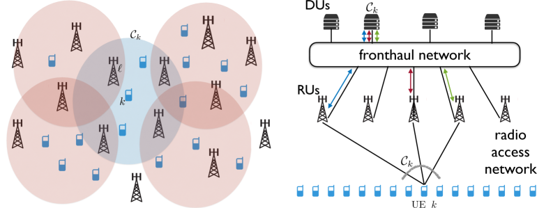
We consider a cell-free massive MIMO RAN and a fronthaul network with a set of routers and DUs , respectively. The RAN consists of single-antenna UEs and RUs , where each RU is equipped with antennas. The UE-RU associations in the RAN are described by a bipartite graph with two classes of nodes (UEs and RUs). The user-centric RU cluster serving user is denoted by . The set of UEs served by RU is denoted by . The set of edges of is such that iff (or, equivalently, iff ). The fronthaul network connects each RU with a subset of the routers, which are partially connected to the other routers and DUs. It is described as a graph , where the edges represent the connections between RUs, routers and DUs. The overall network topology is described by the union of and obtained by merging the common nodes (see Fig. 1).
The matrix describes the channels between the UEs and RU antennas. It consists of the vectors representing the channel between UE and RU . Each channel is a correlated complex circularly symmetric Gaussian vector with mean zero and covariance matrix , where we use the well-known notation . The large-scale fading coefficient (LSFC) corresponding to is defined as It describes the average signal attenuation between RU and user due to distance and other macroscopic effects. The channel coefficients remain constant over blocks of signal dimensions (time-frequency channel uses), referred to as “resource blocks” (RBs). This is a standard model in the (cell-free) massive MIMO literature (see [7, 4]). For simplicity, we focus on a generic resource block and we omit the resource block index in this paper.
II-A Cluster and pilot allocation
The user-centric clusters and uplink (UL) pilots for channel estimation are assigned following the subspace information aided overloaded pilot assignment scheme from [8]. All UEs transmit with the same average energy per symbol and we define the system parameter , where denotes the complex baseband noise power spectral density. Each UE is associated to a cluster of RUs of cardinality at most (a system parameter) with the largest LSFC, provided that
| (1) |
where is a suitable threshold that defines how much larger the useful signal in the presence of maximum possible beamforming gain (equal to ) should be compared to the noise floor. We assume that out of signal dimensions per RB are dedicated to pilots and use a codebook of orthogonal pilot sequences . Let denote the matrix of the orthonormal eigenvectors of spanning the dominant channel subspace, i.e., the subspace containing a sufficiently large fraction of the total channel energy (e.g., see [9, 10]). A RU can assign a pilot to multiple UEs under the condition that the user channel subspaces are approximately mutually orthogonal [2].
We let denote the pilot index of UE . Then, each RU obtains an estimate of the channel vectors using the subspace projection method of [9], given by
where is projected additive white Gaussian noise (AWGN) with i.i.d. components and the sum in the second term contains the channels of co-pilot users with respect to UE . Since orthogonal pilots are used, the contributions of non-co-pilot users are removed from the received pilot signal by multiplying with UE ’s pilot sequence. When and are nearly mutually orthogonal, i.e. , the subspace projection is able to significantly reduce the pilot contamination effect. Since the subspace estimation scheme in [9] achieves virtually the same performance as perfect channel subspace knowledge, we assume channel subspaces to be known in this paper.
II-B Uplink data rates with fronthaul quantization
Let be the UL data symbol of UE (i.i.d. with mean zero and unit variance) at a given channel use of a generic RB. In this work, we consider “smart RUs” that operate according to O-RAN split option 7.2x in the upstream direction. More specifically, our chosen split option is most similar to 7.2x Cat-B ULPI-A, where RUs do channel estimation and equalization locally [11]. As in [9, 2], we consider “local detection with cluster-level combining”, so that the equalized symbol (i.e., a local observation of ) at RU for each UE is sent to the cluster processor of located at some DU over the fronthaul. The cluster-level symbol estimate is then computed at the DU.
In particular, the received UL signal at RU is given by
| (2) |
where is AWGN with components . The local observation is obtained as a linear projection of onto a suitably defined receiver vector , such that
| (3) |
The receiver vectors are computed at RU using the local channel estimates . We consider linear MMSE receivers based on the partial local CSI at RU , given by
| (4) |
where accounts for unknown interference and noise [9]. The cluster processor for user collects the local observations from all RUs and forms a cluster-level combined observation which is then passed to the channel decoder for user as the soft-output of a virtual single user additive noise channel.
Since the fronthaul network has finite capacity links, we let each RU quantize its local observation with bits per sample before sending it to the cluster processor. We use the quantization scheme from [2] based on rate-distortion theory, where depends on the signal strength at RU regarding UE defined as . For a given desired distortion level , each RU uses quantization rate
| (5) |
to send the to the corresponding cluster processor. Note that if for some , then is simply not sent from the RU to the cluster processor since the quantization rate is . This is equivalent to removing RU from cluster . The quantized local observation is given by [2]:
| (6) |
where
| (7) |
and where is a zero-mean Gaussian random variable uncorrelated with and with variance
| (8) |
We let denote the vector of the quantized local observations . The cluster-level combined observation is then given by
| (9) |
where with elements is the cluster-level combining vector that weighs the different local observations. It is computed to maximize the nominal Signal to Interference plus Noise Ratio (SINR) of the channel with input and output , given the local knowledge of the cluster processor . Due to the limited local knowledge of cluster processor , we differentiate between the actual and nominal SINR. The nominal SINR is only used to compute , while the actual SINR is used to compute the actual achievable physical layer user rate. The maximization of the nominal SINR with respect to the vector of combining coefficients is a classical generalized Rayleigh quotient maximization problem and is given in [2].
The resulting actual SINR conditioned on the realization of all the channel vectors is given by [2]
where and . As a performance measure of the physical layer, we consider the UL Optimistic Ergodic Rate (OER) [12] given by
| (10) |
where the expectation is with respect to the small-scale fading, for given values of the LSFCs that depend on the placement of UEs and RUs, the pathloss function and cluster formation.
II-C Downlink data rates with fronthaul quantization
In the downlink (DL), the RUs operate according to split option 7.3 of 3GPP (e.g., see [13]), where the cluster processor sends the information bits to the RU, which carries out the modulation and precoding of the data symbols. Since each RU sends the same signal to UE , the cluster processor sends the same information bits over the fronthaul to the RUs. The DL fronthaul traffic is thus of type multiple-multicast, requiring routers that enable multicast routing. Since the information bits are sent, no quantization is necessary.222However, note that the choice of still affects the DL physical layer rates. If for some , the corresponding RU is removed from .
We use the approximate UL-DL reciprocity of [9, 2] for the DL precoding vectors . We let where are the local linear MMSE combiners for the UL defined in (4) and are the cluster-level combining coefficients as in (9) for the case of zero quantization distortion. The actual local precoding vectors k are obtained by stacking the blocks for all and all-zero blocks for , and normalizing the resulting vector of dimension to have unit norm. In this way, except for the common normalization factor, can be calculated from the local CSI at RU , with sufficiently high resolution finite arithmetic.
We let k denote the -th column of the overall channel matrix and the (coded) information symbol for UE (independent with mean zero and variance ). The received signal sample at UE corresponding to one DL channel use is given by
| (11) |
where, without loss of generality, we scale the received signal such that the noise is . The corresponding DL SINR is given by [2]
| (12) |
We choose uniform power allocation to all data streams, i.e., for all . The corresponding DL OER is given by
| (13) |
Since the information bits are directly sent from the cluster processor located at some DU to the RUs, the fronthaul load corresponding to the DL is equal to the physical layer user rate, i.e., .
II-D Remarks on the fronthaul load
The choice of the split options aims to reduce the fronthaul load by allocating many PHY functions to the RUs, thereby limiting the DU to cluster-level signal processing. We notice that the fronthaul load in this paper only considers quantities directly related to combining and detection in the UL and the information bits in the DL. The coefficients needed to compute the weights and for UL combining and DL precoding, respectively, are not considered. Note that these coefficients are constant during a coherence block of signal dimensions and that channel uses are dedicated to UL and DL data transmission. Assuming and typically in the hundreds or thousands (see [14]), the fronthaul load related to the channel uses for data transmission is relatively large compared to the number of coefficients needed to compute the UL combining and DL precoding weights (see [2]). We assume that these coefficients can be quantized very accurately without increasing significantly the fronthaul load. Therefore, we do not take into account the fronthaul traffic to exchange the coefficients for computing and when defining the UL and DL fronthaul load per RB.
III Problem Statement
In this section, we will describe how the user PHY data rates translate to the UL and DL fronthaul load of the whole system. The network operates in time division duplex mode, where denotes the resource fraction allocated to the DL, and as a consequence is allocated to the UL. We use half-duplex fronthaul links as in [2], i.e., the fronthaul flow constraints must incorporate the fact that the data rate generated by the RUs in the UL is weighted by a factor and the data rate generated by the DUs in the DL is weighted by a factor . The amount of UL fronthaul load transmitted from RU to router , from router to router , and from router to DU regarding user is denoted as , , and , respectively. For the DL, we use a similar notation, where , and is the amount of DL fronthaul data with respect to user sent from router to RU , from router to router , and from DU to router , respectively. The load of any fronthaul link is given by , where is one of the load variables previously introduced.
III-A UL fronthaul load flow
As defined in (5), RU generates a quantization rate of bits per channel use that must be sent via the fronthaul to the DU that is the cluster processor of the user-centric cluster . Since the UL fronthaul contains only unicast flows, for each user every router must satisfy
| (14) |
Considering the TDD resource allocation fraction , the UL fronthaul flow constraint for UE-RU pair is
| (15) | |||
| (16) |
where the UE-RU association binary variable if , and if . Now, let denote the cluster processor placement variable, defined by
We have the constraints that each must be hosted by exactly one DU and a computation capacity constraint per DU, i.e.,
| (17) | |||
| (18) |
where is a computation limit for the number of cluster processors at any DU . Given the cluster processor placement, we note that the received flow relative to user to DU hosting must be not smaller than the sum of source rates over all RUs , i.e.,
| (19) |
We also introduce the individual load variables upper bounds
| (20) |
In particular, this means that if , the rate relative to user from any connected router to will be zero.
III-B DL fronthaul load flow
As explained in Section II-C, the DL fronthaul traffic is of type multiple multicast and the number of information bits per channel use necessary to encode the DL signal for user at each RU is equal to the DL PHY rate . Since the DL fronthaul traffic is of multicast type, the flow conservation at the routers no longer applies (e.g., intermediate nodes may duplicate some input to multiple output links). Considering the data of user , the output data of a router to any RU or router must be less than or equal to the sum input data from the cluster processor and other routers, i.e.,
| (21) |
and
| (22) |
In the DL, the DU hosting must transmit at least bits per channel use to the connected routers, i.e.,
| (23) |
On each individual link to a router , the DU needs to transmit at most bits and only the DU hosting cluster transmits fronthaul data for user . These two constraints are summarized as
| (24) |
The constraint that guarantees that each RU receives fronthaul bits for user is formulated as
| (25) |
III-C Fronthaul optimization problem
Let the maximum link loads for RU-router, router-router, and router-DU links (with corresponding weights ). Further, , and denote the ensemble of all , UL load and DL load variables, respectively. Then, we can use the mixed-integer linear program (MILP) of [2] for joint optimization:
| (26a) | |||||
| s. t. | (26e) | ||||
where constraints (26e)-(26e) ensure that each link load is less than the link capacity. Note that MILPs can be solved by existing highly efficient optimization tools [15]. To implement (26), we utilize the MATLAB function intlinprog.
IV Numerical Results
We start this section with an overview of the considered network and parameters, before showing the impact of different and on the PHY SE and fronthaul load. Our cell-free massive MIMO network has an area of with a torus topology to avoid boundary effects. The LSFCs are given by the 3GPP urban microcell pathloss model from [16, Table 7.4.2-1]. The spatial correlation between antennas follows the one-ring scattering model with angular support , i.e., it is centered at angle of the LOS between RU and UE with angular spread . Then, the channel between UE and RU is given by
where the index set includes all integers such that (where angles are taken modulo ), is the submatrix extracted from the unitary DFT matrix by taking the columns indexed by , and has i.i.d. components . Hence, is a Gaussian zero-mean random vector confined in the subspace spanned by the columns of .
IV-A Simulation setup
We consider a system with RUs, each equipped with antennas and placed on a rectangular grid. We set , , the maximum cluster size , and the SNR threshold in (1). We define the expected pathloss at distance between UE and RU, where is the radius of a disk of area equal to . The UL energy per symbol of each UE is (i.e., 0 dB) and thus depends on the RU density and the number of RU antennas. This choice leads to a certain level of coverage overlap among RUs, such that each UE is likely to associate with several RUs. The complex baseband noise power density is . The RUs are partially connected to routers, which in turn are partially connected to DUs.333We use the same fronthaul links as [2] and refer the reader to [2] for a description and illustration of what links exist between RUs, routers and DUs. For each of the DUs, we impose . The optimization weights , , are set to .
Each coherence block contains signal dimensions, of which are used for UL pilots and . We compute the expectation in (10) and (13) over channel realizations and define the total UL/DL SE, i.e., the UL/DL PHY SE in bits per channel use (or bit/s/Hz) of all users, as and . The total sum PHY SE is given by .
IV-B Evaluation of the user load and quantization level
We evaluate the impact of the user load and distortion level on the fronthaul load and PHY SE. We let , which ranges from a lightly loaded to an overloaded system compared to (see [17]). Recall that a UE-RU association is removed if . Therefore, the smallest distortion level is chosen such that , where . As is increased, in (5) decreases and more UE-RU associations are removed.
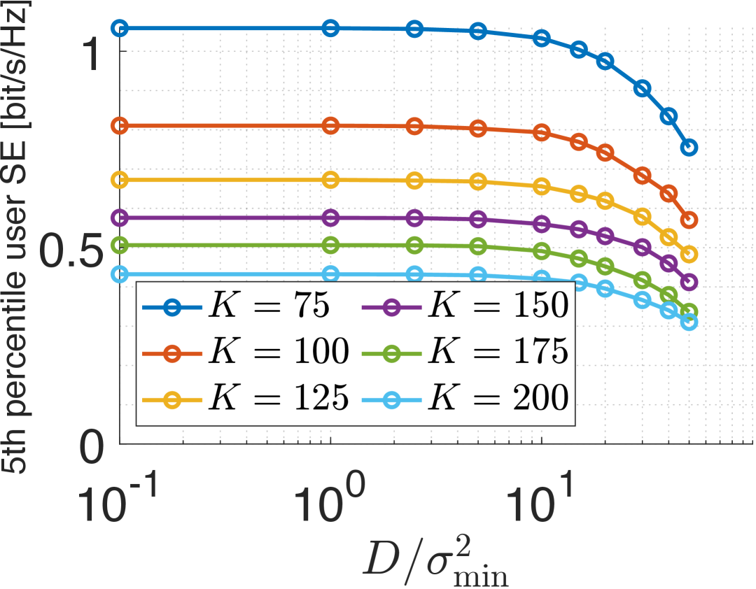
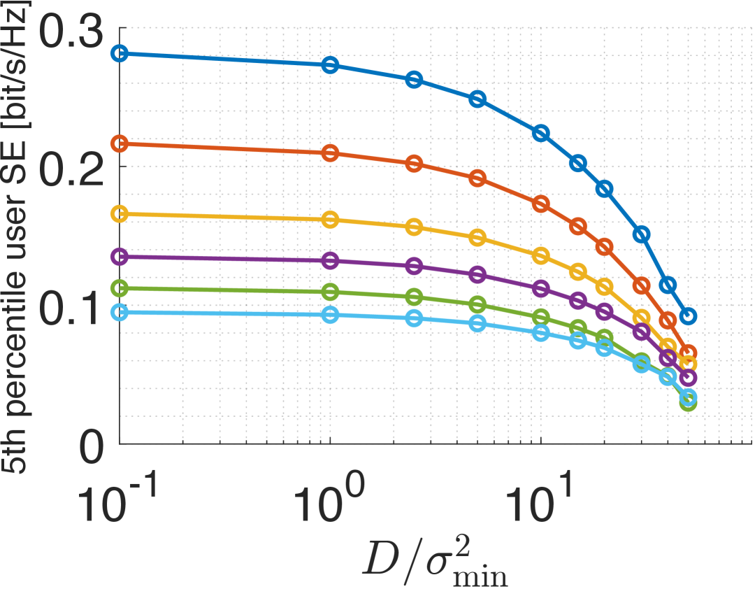
As Fig. 2 shows, each increase of leads to a significant reduction of the fronthaul load, i.e., , while the sum PHY SE only decreases for large . We note that as is increased, the fronthaul load becomes smaller for large than for small in some cases. This is explained by smaller for large due to multi-user interference. Increasing leads to more UE-RU associations being removed and reduced quantization rates compared to a low user load. When is increased in the high distortion regime, the sum PHY SE first decreases slightly and then, as more UE-RU associations are removed, significantly. Fig. 3 confirms and explains this behavior. The degradation of the 5th percentile DL user SE is observed at . No quantization is needed in the DL, so this effect is caused solely by removing UE-RU associations. The degradation of in the UL occurs for smaller due to fronthaul quantization distortion. Since a larger fraction of resources is used in the DL, the impact of on in Fig. 2 becomes more significant for . We further notice that the average cluster size decreases from nearly RUs with to and RUs at and , respectively.
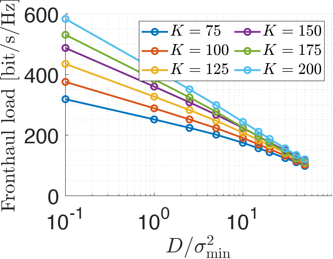
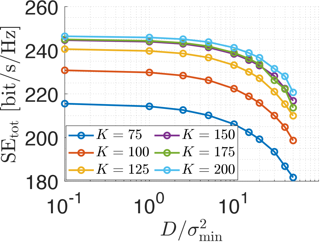
As another result from Fig. 2 we observe that the sum SE grows with larger , but only in the range . For , multi-user interference becomes more severe and it is recommended not to serve much more than UEs.
IV-C Concluding remarks and future work
A wide range of user loads can be supported by the same cell-free massive MIMO RAN and fronthaul network if the distortion level is optimized. For example, in this setup, for and for are good choices. Then, the fronthaul load for the recommended user load is between and bit/s/Hz (i.e., in a relatively small margin) and the PHY SE is degraded only very slightly compared to smaller . This is also an interesting result for scheduling problems. If the total number of users in the network area is varying, the scheduler can flexibly react to different user loads and demands, and change the number of simultaneously active users without overloading the fronthaul network. We conclude that dense cell-free massive MIMO deployments are a very promising approach to achieve resilient 6G (radio access and fronthaul) networks with regard to varying user densities.
Future work includes investigating the impact of the distortion level for different fronthaul network topologies and fronthaul load optimization algorithms, and to study scheduling with flexible user loads under fronthaul constraints.
V Acknowledgments
The authors acknowledge the financial support by the Federal Ministry of Research, Technology and Space of Germany in the programme of “Souverän. Digital. Vernetzt.” Joint project 6G-RIC, project identification number 16KISK030.
References
- [1] H. Q. Ngo et al., “Ultradense Cell-Free Massive MIMO for 6G: Technical Overview and Open Questions,” Proceedings of the IEEE, 2024.
- [2] Z. Li et al., “Joint Fronthaul Load Balancing and Computation Resource Allocation in Cell-Free User-Centric Massive MIMO Networks,” IEEE Transactions on Wireless Communications, vol. 23, no. 10, pp. 14 125–14 139, 2024.
- [3] A. Joshi et al., “Fronthaul Resource Optimization for Cell-Free Massive MIMO Networks,” in 2024 14th International Workshop on Resilient Networks Design and Modeling (RNDM), to appear. IEEE, 2024.
- [4] E. Björnson et al., “Scalable Cell-Free Massive MIMO Systems,” IEEE Transactions on Communications, vol. 68, no. 7, pp. 4247–4261, 2020.
- [5] I. Chih-Lin et al., “Rethink fronthaul for soft RAN,” IEEE Communications Magazine, vol. 53, no. 9, pp. 82–88, 2015.
- [6] R. B. Dilmaghani et al., “On designing communication networks for emergency situations,” in 2006 IEEE International Symposium on Technology and Society. IEEE, 2006, pp. 1–8.
- [7] T. L. Marzetta, “Noncooperative cellular wireless with unlimited numbers of base station antennas,” IEEE Transactions on Wireless Communications, vol. 9, no. 11, pp. 3590–3600, 2010.
- [8] N. Osawa et al., “Overloaded Pilot Assignment with Pilot Decontamination for Cell-Free Systems,” in 2023 IEEE Wireless Communications and Networking Conference (WCNC), 2023, pp. 1–6.
- [9] F. Göttsch et al., “Subspace-Based Pilot Decontamination in User-Centric Scalable Cell-Free Wireless Networks,” IEEE Transactions on Wireless Communications, vol. 22, no. 6, pp. 4117–4131, 2023.
- [10] A. Adhikary et al., “Joint Spatial Division and Multiplexing—The Large-Scale Array Regime,” IEEE Transactions on Information Theory, vol. 59, no. 10, pp. 6441–6463, 2013.
- [11] Ericsson, “Driving Open RAN forward – An improved open fronthaul interface bringing performance to Open RAN,” Tech. Rep., 2023.
- [12] G. Caire, “On the Ergodic Rate Lower Bounds With Applications to Massive MIMO,” IEEE Transactions on Wireless Communications, vol. 17, no. 5, pp. 3258–3268, 2018.
- [13] ITU-T G-series Recommendations – Supplement 66, “5G Wireless Fronthaul Requirements in a Passive Optical Network Context,” Geneva, Switzerland, Sep 2020.
- [14] R. P. Torres et al., “A lower bound for the coherence block length in mobile radio channels,” Electronics, vol. 10, no. 4, p. 398, 2021.
- [15] E. El Haber et al., “Joint Optimization of Computational Cost and Devices Energy for Task Offloading in Multi-Tier Edge-Clouds,” IEEE Transactions on Communications, vol. 67, no. 5, pp. 3407–3421, 2019.
- [16] 3GPP, “Study on channel model for frequencies from 0.5 to 100 GHz (Release 16),” 3GPP Tech. Spec. 38.901, 12 2019, Version 16.1.0.
- [17] F. Göttsch et al., “Fairness Scheduling in User-Centric Cell-Free Massive MIMO Wireless Networks,” IEEE Transactions on Wireless Communications, vol. 23, no. 9, pp. 11 942–11 957, 2024.