Excited two-dimensional magnetopolaron states in quantum well
of resonant tunnel junction
Abstract
Tunnel spectroscopy is used to probe the electronic structure in GaAs quantum well of resonant tunnel junction over wide range of energies and magnetic fields normal to layers. Spin degenerated high Landau levels () are found to be drastically renormalised near energies when the longitudinal optical-phonon () and cyclotron energy () are satisfied condition , where . This renormalisation is attributed to formation of resonant magnetopolarons, i.e. mixing of high index Landau levels by strong interaction of electrons at Landau level states with LO-phonons.
In polar semiconductors, such as GaAs, electrons interact with LO phonons to form polarons, i.e. the bare electron states are renormalized. If a magnetic field B is applied perpendicular to the plane of the GaAs quantum well, 2D electron states are quantized into Landau levels (LL) of index . Filling of empty Landau levels in the QW by tunnelling current causes excitation of resonant magnetopolarons Sarma (1984); Peeters and Devreese (1985) when resonant condition , where are integers, is satisfied. The resulting magnetopolarons can be measured experimentally by monitoring density of states in the quantum well by tunnel spectroscopy. Previously only interaction of ground Landau state with and ones via LO-phonons have been detected by means of phonon assisted tunnelling spectroscopy G.S.Boebinger et al. (1990). It was displayed as anticrossing of the position of the peaks related to the double phonon assisted tunnelling into LL () and single phonon assisted tunnelling into LL () in the fan diagram.
In this work we present studies of electron structure of the QW in a magnetic field normal to the well plane by means of tunnel spectroscopy. The AlGaAs/GaAs/AlGaAs heterostructure was double barrier structure incorporating a layer of InAs quantum dots (QD) in the center of the well. The dots are charged and create a considerable amount of disorder in the well. In this case the number of elastic scattering assisted tunnelling events with only energy conservation, but not momentum conservation is increased considerably. It means that direct tunnelling between different LL’s in the emitter and collector is permitted and one can monitor the density of states in a magnetic field in the QW by means of both elastic and inelastic tunnelling spectroscopy. The phonon assisted tunnelling channel is opened independently of sample quality. As the result we have found strong interaction between LL’s of different indices () in the well near energies when the longitudinal optical-phonon () and cyclotron energy () are satisfied condition , where . This was attributed to formation of resonant magnetopolaron states, i.e. mixing of different LLs by interaction with LO-phonons.
Samples grown by MBE comprised (in the order of growth): a lightly -doped, -nm–thick GaAs layer ( cm-3); a -nm–thick GaAs layer ( cm-3); a -nm–thick undoped GaAs spacer layer; a -nm–thick barrier layer; a nm undoped GaAs layer; a monolayer (ML) InAs (with growth rate ML/s to form InAs QD); a -nm–thick undoped GaAs layer; a -nm–thick barrier; a nm undoped GaAs; a -nm–thick GaAs layer ( cm-3); and a -nm–thick GaAs layer () cap-layer. The samples were characterised by photoluminescence (PL) spectroscopy, which confirmed the existence of the corresponding QD or WL emission. Ohmic contacts were obtained by successive deposition of layers and subsequent annealing. Mesa structures, with diameter between and , were fabricated by conventional chemical etching.
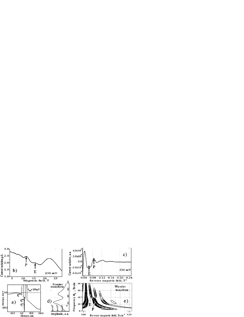
The band diagram of the structure under voltage bias is shown in Figure 1(a). With the application of a sufficient bias to the structure, an accumulation layer is formed adjacent to the barrier, which serves as two-dimensional emitter. The details of resonant tunnelling through this double barrier structures with disorder introduced by QD was published earlier Yu.V.Dubrovskii et al. (2001). The tunnelling current oscillates with varying magnetic field with constant bias applied to structure (Fig. 1(b)). Peaks are observed, corresponding to tunnelling into Landau states of the ground subband in the well with and without phonon emission. We analyse only the data for fields above , when only the lowest energy Landau level is occupied in the emitter. All measurements were carried out at temperature K.
Careful analysis of the experimental data at each allowed us to identify all peaks in a magnetotunnelling spectrum. Three different techniques have been used to do this: identification of peak position in vs. LL number, Fourier analysis, and more sophisticated wavelet analysis. The wavelet analysis Yu.V.Dubrovskii et al. (2001) is a mathematical tool, which allows to decompose a signal in the locally confined waves (Wavelets).
The general expression for WL transform is , where is so called ”mother” wavelet function. The transform result is a function of two variables. Parameter is analog of frequency in the Fourier transform. Each is localized around . For WL decomposition of our experimental data we have used the Morlet Louis et al. (1997) ”mother” function , which is a trigonometric function modulated by Gaussian. The parameter determines the number of oscillations one wants to use for the analysis and should be optimised in each specific case. In more details the procedure of wavelet analysis is described in paper web .
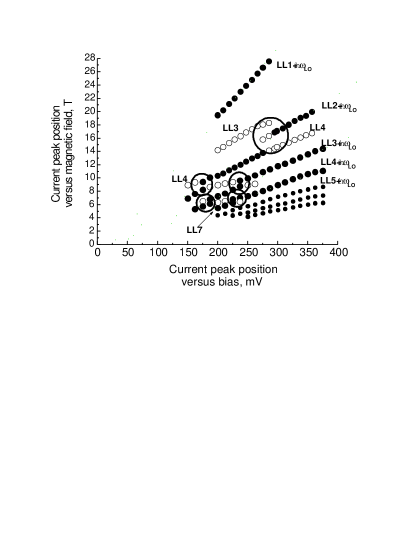
The result of WL analysis of tunnelling spectra recorded at mV is shown in Figure 1. Fig. 1(b) and Fig. 1(c) show recorded signal versus magnetic field and reverse magnetic field respectively. The result of Fourier transform is shown in Fig 1(d). Figure 1(e) shows result of WL transform. This is the 3-dimensional picture, where the amplitude of the Wavelet transform (z-axis) is presented versus frequency (y-axis) and the inverse magnetic field (x-axis). As usual tunnelling with and without phonon emission Chukalina et al. (2004) results in two sets of oscillations periodical in reverse magnetic field in tunnelling spectrum at constant bias, with frequencies and respectively. Here and are the effective mass and charge of an electron; is the Plank constant; , , are the energies of the ground quasibound states in the emitter and in the quantum well (QW) respectively, is the longitudinal optical phonon energy. Peaks in the tunnelling spectrum related to phonon assisted tunnelling into LL belong to low frequency set of oscillation and the elastic scattering peaks to high frequency set. Fourier transform spectrum (Fig. 1(d)) shows evidently two frequencies separated by T. Than meV, which is equal to energy of LO-phonon ( meV) in GaAs with good accuracy as expected. Wavelet transform permits one to determine the origin of each peak in the tunnelling spectrum. For example, arrows labelled by ”E” in Figures 1(b) and 1(c) indicate the same peak. Appropriate maximum in the amplitude of the Wavelet transform (Figure 1(e)), also indicated by arrow ”E”. Wavelet data indicate that the peak belongs to the high frequency set of oscillations and therefore is related to the elastic tunnelling into LL with . The LL index could be easy determined by standard procedure. In the same manner one can conclude that peak labelled by ”P” appears due to the phonon assisted tunnelling into LL with . (More precisely one should say that peak ”P” is the superposition of two peaks, one with higher amplitude related with phonon assisted tunnelling and another of the smaller amplitude with direct tunnelling into LL with ). In this way we have identified all the peaks in the tunnelling spectra at different bias voltages. Fan diagram in Figure 2 summarised peak positions versus magnetic field in tunnelling spectra. Solid circles - position of peaks due to phonon assisted tunnelling. Open circles - direct tunnelling from the ground Landau level in the emitter to Landau level of higher indexes in the quantum well.
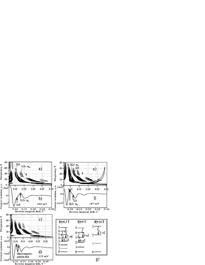
Strong interaction between LL of different indexes have been observed in tunnelling spectra with . The details of this interaction between and Landau levels () is shown in Figure 3, as example. Tunnelling spectra versus reverse magnetic field for three different biases are presented in Figures 3(b), (d), and (f). Figures 3(a), (c), (e) show Wavelet transforms of the tunnelling spectra, respectively. Since these peaks move versus bias with different velocity, one could expect that without interaction they should crossed at the intermediate bias voltage, mV in this case. Contrary we see typical anticrossing behaviour of the peaks, first, the exchange of oscillator intensity, second, the same peak is related to direct tunnelling on one side or phonon assisted-tunnelling on another side away from strong interaction point. Circles in the fan diagram (Figure 2) indicate the regions where different levels are anticrossing. Next magnetopolaron states have been identified in this work:
This is illustrated in Figure 3(g).
In conclusion, we have observed and identified a set of two-dimensional resonant excited magnetopolaron states, i.e. mixing of different high indexes Landau levels by optical phonons, for electron tunnelling into a quantum well with embedded quantum dots.
Acknowledgements.
This work was supported by RFBR (04-02-16870, 02-02-22004), PICS (1577), RAS programs ”Quantum Macrophysics”, and ”Low-Dimensional Quantum Nanostructures”, FTNS program, EPSRC, and RS (UK). We are grateful to Dr. H. Funke for the support during the software development.References
- Sarma (1984) S. D. Sarma, Phys. Rev. Lett. 52, 859 (1984).
- Peeters and Devreese (1985) F. Peeters and J. Devreese, Phys. Rev. B 31, 3689 (1985).
- G.S.Boebinger et al. (1990) G.S.Boebinger, A. Levi, S. Schmitt-Rink, A. Passner, L. Pfeiffer, and K. West, Phys. Rev. Lett. 65, 235 (1990).
- Yu.V.Dubrovskii et al. (2001) Yu.V.Dubrovskii, E. Vdovin, A. Patane, P. Brunkov, I. Larkin, L. Eaves, P. Main, D. Maude, J.-C. Portal, D. Ivanov, et al., Nanotechnology 12, 491 (2001).
- Louis et al. (1997) A. Louis, P. Maass, and A. Rieder, Wavelets: Theory and Applications (John Wiley& Sons Ltd, 1997).
-
(6)
(The MathWorks,
http://www.mathworks.com/products/wavelet
/description/overview.shtml). - Chukalina et al. (2004) M. Chukalina, H. Funke, and Y. Dubrovskii, Low Temperature Physics 30, 930 (2004).