Measurement of the Longitudinal Polarization of the
HERA Electron Beam Using Crystals and
the ZEUS Luminosity
Monitor111Contribution to the Workshop on Channeling
and Other Coherent Crystal Effects at Relativistic
Energies, Århus, Denmark, July 10–14, 1995
Abstract
A measurement of the longitudinal polarization of the electron beam at HERA utilizing coherent interactions of high energy photons in crystals is described. Modification of existing facilities would allow an independent polarization measurement and a verification of birefringence phenomena in crystals for 20–30 GeV photons. Relevant experimental issues and systematic uncertainties are also presented.
1 Introduction
High longitudinal polarization (%) of the electron beam has been routinely achieved at HERA since the installation of so-called spin rotators which convert the naturally acquired transverse polarization to the experimentally required longitudinal polarization [1]. Longitudinal polarization is currently available only at the interaction point of the fixed-target experiment HERMES; spin rotators are planned for installation at the collider experiments, ZEUS and H1. The success of the physics program with polarized electrons (and possibly polarized protons) at HERA relies heavily on the precision of the polarization measurement.
Measurement of the polarization of the electron beam at HERA is currently performed by Compton-scattering laser photons off the electron beam and measuring the spatial asymmetry of the scattered photons [2]. The estimated accuracy of this method is about 2%. An independent polarization measurement is of interest as it would allow for better control of systematic errors and cross-calibration of the polarimeters222Recently, a measurement of asymmetries in large angle ep bremsstrahlung was proposed as an interesting method of polarization monitoring at colliders [3]..
In 1988 the measurement of the electron beam polarization using bremsstrahlung attenuation in crystals was proposed for use at the LEP collider [4]. We developed a similar method for use at HERA utilizing an existing detector of high energy bremsstrahlung which is presently used for the luminosity measurement in the ZEUS experiment [5].
2 Principles of the Method
It is aimed to achieve at least 2% accuracy of the measurement of the electron beam longitudinal polarization. The measurement would be done in three steps:
-
1.
calculation of the correlation between the electron longitudinal polarization and the circular polarization of high energy bremsstrahlung (including detector effects);
-
2.
conversion of the photon polarization from circular to linear (or at least to strongly elliptic);
-
3.
measurement of the linear polarization of the photon.
The first point is well understood and theoretical relations are available; the second step has been demonstrated theoretically but has never been realized experimentally, and it is very interesting on its own; the third step has been demonstrated experimentally confirming the theoretical predictions, therefore should not pose many problems.
For a longitudinally polarized electron beam, bremsstrahlung photons with energies close to the incident electron energy are circularly polarized to the same degree as the electron beam. The bremsstrahlung polarization can be deduced for an initial electron longitudinal polarization, , and bremsstrahlung photon circular polarization, , from the following differential cross-section [6]:
| (1) |
where y is the fraction of the initial electron energy, , carried by the bremsstrahlung photon, is proton beam energy, and are the proton and electron masses, is the fine structure constant and is the classical electron radius, and it is assumed that the polarization of the scattered electron is not measured. From Eq. 1 one can derive the following relation between the electron beam longitudinal polarization333Beam polarization is defined as , where are numbers of particles with ‘+’ and ‘–’ polarization, respectively., , and the bremsstrahlung circular polarization, :
| (2) |
It follows that at y=1 , and that is near if y is close to 1, e.g. if y=0.9 then .
In 1962 Cabibbo et al. proposed the use of crystals for producing and analyzing the linear polarization of high energy photons [7, 8]. Photons which impinge on a crystal under small angles with respect to the crystallographic axes (or planes) undergo a coherent interactions with strings of atoms residing in lattice sites when the direction of the recoil momentum, q, coincides with one of the crystal axes and its value is related to the interplanar distance a, . For linearly polarized photons the cross-section for pair creation, and hence the photon attenuation in a crystal, depends significantly on the angle between the plane of the photon polarization and the crystal symmetry plane. A crystal can be used as a polarizer, since an initially unpolarized photon beam becomes linearly polarized after traversing the thick crystal, as shown experimentally at Cornell and SLAC [9, 10]. The crystal can also be used as an analyzer by measuring the attenuation of the photon beam as a function of the crystal orientation. One infers the linear polarization of the incident photon beam from the variation of the photon attenuation for different crystal positions, e.g. if the incident photons have a linear polarization and hit the crystal under a small angle with respect to the (110) axis, then the attenuation of the photon beam changes with angle between the polarization and the (001) planes as follows [7]:
| (3) |
where I(0) is the initial intensity and I(x) is the intensity of the photon beam after traversing the crystal thickness x, A is the crystal analyzing power and is equal to the linear polarization of an initially unpolarized photon beam after traversing the crystal. The crystal should be rotated around the photon beam axis in such a way that the angle is fixed.
However, bremsstrahlung is circularly polarized therefore to use such crystal analyzers one needs to convert the polarization of high energy photons from circular to linear polarization. A polarization converter for high energy photons was proposed by Cabibbo et al. [11] who discovered (and utilized) the property of birefringence of crystals, i.e. the non-zero difference of the refractive indices, , for parallel and perpendicular polarizations (with respect to the crystallographic planes or axes) of high energy photons. The appropriate converter thickness, d, can be obtained from the following formula:
| (4) |
where is the photon energy. The converter is however also a polarizer, therefore the linear polarization behind it, , is higher than the initial photon circular polarization [12]:
| (5) |
where is the converter analyzing power.
The other aim of the proposed experiment is to verify experimentally the exciting theoretical prediction of crystal birefringence for high energy photons. To show, in particular, that not only visible light but also many-GeV photons can travel at a speed smaller than the speed of light in vacuum! In fact, only when this effect has been demonstrated can the proposed method of polarization measurement be implemented.
3 Experimental Set-Up
A polarization measurement using crystals could be performed utilizing existing detectors of the ZEUS luminosity monitor. A detailed description of the luminosity detectors can be found elsewhere [5, 14]. The ‘branch’ used for the bremsstrahlung photon detection is briefly described here. The photon detector is located about 100 m from the interaction point (IP), upstream of the proton beam (see Fig. 1). It consists of a mm thick circular (100 mm in diameter) copper-beryllium exit window in the HERA vacuum chamber at 92 m from the IP, a 12 m long vacuum pipe, a carbon-lead absorber ( one radiation length) shielding against synchrotron radiation, and a lead-scintillator ‘sandwich’ calorimeter at about 107 m from the IP. The calorimeter sampling step is with the first scintillator plate (‘presampler’) being 4 times thicker than the nominal 0.26 mm thickness, to compensate for the energy loss in the absorber ( in total). The signal from the calorimeter scintillator plates is read-out by two (up and down) wavelength shifter plates connected by light guides to two photomultiplier tubes. The calorimeter is equipped with a position detector with separate readout at a depth of .

Here, we propose to change the experimental setup of the ZEUS luminosity monitor in order to accommodate a simultaneous polarization measurement. The modification requires replacement of the carbon filter and the first 1 lead plate with two thick crystals serving as the polarization converter and analyzer. Additionally, for the detection of the photon interaction in the crystals (needed in the photon attenuation measurement) a detector sensitive to charged particles has to be placed behind the analyzer, see Fig. 2.
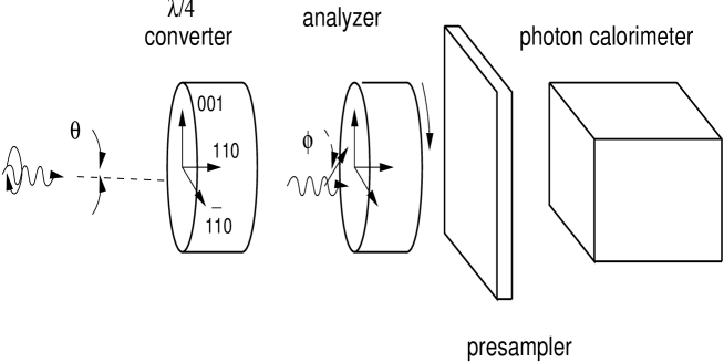
Both crystals would be installed on remotely controlled goniometers, providing three degrees of freedom. A 3 thick plate would be installed at a fixed (but adjustable) angle between its crystallographic axes and the incident photon direction. A 1.5–2 thick analyzer would be placed directly behind the converter with a small angle between one of its symmetry axes and the incident photon beam direction, and would continuously rotate about the photon beam axis. To detect photon interactions in the crystals the lead plate in front of the presampler has to be removed and an additional separate readout must be installed. The detector would tag a photon interaction in the crystals if the energy deposit in the presampler would exceed the signal from one minimum ionizing particle.

4 Experimental Issues
The transverse size of the photon beam at the photon detector is about 8 cm horizontally and 6 cm vertically which requires crystals with cross-sections of about . The total thickness of the crystals is limited to about 5 to keep the photon beam attenuation at an acceptable level (1/50) and to avoid large non-linearities in the photon energy measurement. There are only three types of crystals available in such large bulk quantities: highly oriented pyrolytic graphite, and silicon and germanium crystals. Pyrolytic graphite behaves as a single crystal only in one dimension and was used in the Cornell and SLAC experiments.
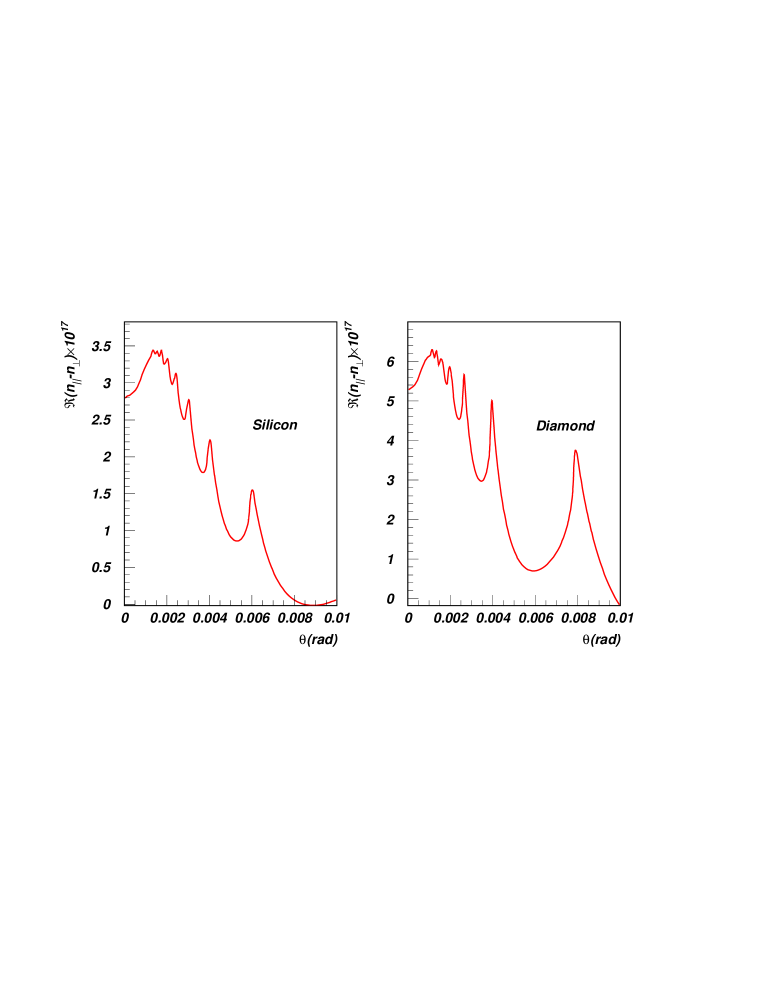
In Tab. 1 the crystal parameters used in the calculation of for five crystal types (diamond and copper were considered for reference) are shown, following the notation and definitions in [8, 11]. In Fig. 4 in diamond and silicon crystals is shown for 27 GeV photons as a function of the incident angle, , measured with respect to the (110) axis444The re-calculation of for a copper crystal using analytic formulae from [11, 8] yielded results different than those given in [11] (as was also observed in [13]). We believe that it is due to some numerical mistake in [11] as we found good agreement between our calculations and results published in [15] for in silicon crystals.. The distributions show similar behavior – series of narrow, small peaks on top of a broad (about 1 mrad wide) peak at 1.5–2 mrad incident angle. Additional smearing is expected due to spread of direction of crystal axes (‘mosaic spread’), which is particularly large for graphite crystals.
| Crystal | Lattice Constant | Screening Parameter | Thermal Factor |
|---|---|---|---|
| (Lattice Type) | a () | b () | A () |
| Graphite (pyrolytic) | 869 | 3731 | 227 |
| Silicon (diamond) | 1400 | 2112 | 282 |
| Copper (fcc, at 77 K) | 935 | 1360 | 166 |
| Germanium (diamond) | 1463 | 1316 | 286 |
| Diamond | 922 | 3731 | 126 |
| Crystal Type | d () | (mrad) |
|---|---|---|
| Graphite (pyrolytic) | 1.7 | |
| Silicon (diamond) | 3.5 | 1.5 |
| Copper (fcc, at 77 K) | 1.0 | 1.2 |
| Germanium (diamond) | 4.4 | 1.3 |
| Diamond | 1.5 | 1.1 |
In Tab. 2 results are given for the thickness of the converter, d, at the best angle of incidence, , for 27 GeV photons (for all crystals was measured between the photon momentum and the (110) axis, except for the graphite crystal where it was measured with respect to (002) axis). It is clear that the required converter thickness (in radiation lengths) decreases for heavier crystals favoring usage of silicon or germanium crystals. The converter thickness is unfortunately rather large, which does not leave much room for the analyzer.
The crystals would be subjected to huge synchrotron radiation dosages of Gy/year which should not pose major problems according to recent results from SPS beam extraction experiments where protons/ fluences (equivalent to about Gy energy deposits) did not change significantly the performance of silicon crystals [16]. As synchrotron light would deposit about 300 W power in the crystals, the crystals might require cooling (as in the SLAC experiment [10]) to avoid large temperature-dependent effects.
The crystal alignment is not critical (of the order of rad) due to the photon beam divergence (rad) and the crystal mosaic spread of at least 3 mrad for pyrolytic graphite, for example.
The rotating analyzer will cause a time dependent photon absorption and could bias the simultaneous luminosity measurement, however recent results from CERN indicate that the change of energy absorption in crystal is small [17]. Additionally, if the rotation is uniform and not too slow (i.e. faster than the updates of the integrated luminosity every 16 s or so) this effect should average out.
Beside many experimental effects which would have to be well controlled, as efficiency of the presampler or contribution of the backgrounds and accidental coincidences, there are three major parameters which have to be calibrated: converter phase shift, , and the analyzing powers of the converter and of the analyzer. If the crystals are made of the same material, A and can be measured using standard procedures – measurement of the product, , polarizing linearly an initially unpolarized photon beam with the converter and measuring the resulting polarization with the analyzer [12, 4]. Then, A and can be resolved according to the crystal thicknesses.
The phase shift measurement is more involved and we propose to utilize the converter behavior for energies different than the nominal energy when should be equal to . It would require the simultaneous measurement of the bremsstrahlung polarization at the electron beam energy and, for example, at a half of the beam energy. For y=0.5 , and A, can be predicted and/or calibrated. The remaining change of the measured polarization will be due to the change of the phase shift. This effect may be used for the measurement of the nominal phase shift according to the following formula:
| (6) |
where are the converter analyzing powers, and are the linear polarizations measured with analyzer, at high and low photon energies, respectively. Such a calibration procedure can be repeated at many photon energies and its precision is limited only by the uncertainty of the analyzing powers A and , as the energy scale in the ZEUS luminosity monitor is precisely controlled [18]. Most probably the calibration data would be taken using electron-gas bremsstrahlung which offers more stable and clean experimental conditions, although at the cost of the data statistics.
5 Conclusions
Polarized high energy bremsstrahlung at HERA offers unique opportunity for studying coherent effects in crystals. Existing detectors used in the ZEUS experiment for the luminosity measurement, after some modifications, would allow for detailed studies of these effects in a 5–30 GeV photon energy range. The calibration procedures of the relevant crystal parameters, in particular the calibration procedure of crystal phase shift proposed in this paper, could be done with experimental data rather than with theoretical models. This opens opportunity of the novel technique of the measurement of the the electron beam longitudinal polarization using crystals. Although this is a very demanding task in the difficult HERA environment (huge beam collision rates and severe background conditions) we believe that polarization measurement with 2% precision is feasible.
Acknowledgment
The author would like to thank Vladimir Maisheev for pointing out the numerical problems with the published data on and for useful comments and explanations. I thank very much Antonio Di Domenico for early discussions on this subject and for providing me with useful information. I am very grateful to Mark Lomperski for critical reading of the manuscript. I wish to thank very much the Workshop organizers for inviting me to Århus and supporting my stay there.
References
- [1] D.P. Barber et al., Phys. Lett. B343 (1995) 436.
- [2] D.P. Barber et al., Nucl. Instr. Meth. A329 (1993) 79.
- [3] A.B. Arbuzov et al., One-Spin Asymmetries in Pair Production and Bremsstrahlung Processes, E2–95–44 preprint, submitted to Phys. Lett. B, Dubna, 1995.
- [4] G. Zorzi, G. Diambrini-Palazzi and A. Di Domenico, Use of Single Bremsstrahlung with Crystals for Measuring Longitudinal Polarization at LEP, in: Polarization at LEP, Vol.2, 64–81, CERN, 1988.
- [5] J. Andruszków et al., First Measurements of HERA Luminosity by ZEUS Lumi Monitor , DESY 92–066, May 1992.
- [6] M. Caffo, R. Gatto, E. Remiddi and F. Semeria, Nucl. Phys. B327 (1989) 93.
- [7] N. Cabbibo, G. Da Prato, G. De Franceschi and U. Mosco, Phys. Rev. Lett. 9 (1962) 270.
- [8] N. Cabbibo, G. Da Prato, G. De Franceschi and U. Mosco, Nuovo Cimento, 27 (1963) 979.
- [9] C. Berger et al., Phys. Rev. Lett., 25 (1970) 1366.
- [10] R.L. Eisele et al., Nucl. Instr. Meth., 113 (1973) 489.
- [11] N. Cabbibo, G. Da Prato, G. De Franceschi and U. Mosco, Phys. Rev. Lett. 9 (1962) 435.
- [12] D. Clarke and J.F. Grainger, Polarized Light and Optical Measurements, Oxford, Pergamon Press, 1971.
- [13] A. Di Domenico, PhD Thesis, Rome 1990, unpublished.
- [14] K. Piotrzkowski, Experimental Aspects of the Luminosity Measurement in the ZEUS Experiment, DESY–F35D–93–06, Oct 1993, PhD Thesis.
- [15] V.A. Maisheev, V.L. Mikhalev and A.M. Frolov, Sov. Phys. JETP, 74 (1992) 740.
- [16] K.Kirsebom et al., these proceedings.
- [17] C.Biino et al., these proceedings.
- [18] K. Piotrzkowski, Zeit. f. Phys. C67 (1995) 577.