A measurement of parity-violating gamma-ray asymmetries in polarized cold neutron capture on 35Cl, 113Cd, and 139La
Abstract
An apparatus for measuring parity-violating asymmetries in gamma-ray emission following polarized cold neutron capture was constructed as a 1/10th scale test of the design for the forthcoming experiment at LANSCE. The elements of the polarized neutron beam, including a polarized 3He neutron spin filter and a radio frequency neutron spin rotator, are described. Using CsI(Tl) detectors and photodiode current mode readout, measurements were made of asymmetries in gamma-ray emission following neutron capture on 35Cl, 113Cd, and 139La targets. Upper limits on the parity-allowed asymmetry were set at the level of for all three targets. Parity-violating asymmetries were observed in 35Cl, , and 139La, , values consistent with previous measurements.
keywords:
parity violation , polarized neutrons , radiative neutron capturePACS:
11.30.Er , 13.75.Cs , 07.85.-m , 25.40.Lw, , , , , , , , , , , , ,
1 Introduction
The NPDGamma experiment [1, 2] is under construction at the Los Alamos Neutron Science Center (LANSCE) at Los Alamos National Laboratory. This includes construction of Flight Path 12 at the Manuel Lujan Jr. Neutron Scattering Center at LANSCE, which will be a pulsed cold neutron beamline dedicated to fundamental physics. The goal of the experiment is to measure the parity-violating directional gamma-ray asymmetry in the reaction to an accuracy of , which is approximately 10% of its predicted value [3]. This measurement will provide a theoretically clean determination of the weak pion-nucleon coupling and resolve the long-standing controversy over its value [4, 5, 6]. The experiment will consist of a pulsed, cold neutron beam, transversely polarized by transmission through polarized 3He, incident on a liquid para-hydrogen target. The 2.2 MeV gamma-rays from the capture reaction will be detected by an array of CsI(Tl) scintillators coupled to vacuum photodiodes and operated in current mode. In Fall 2000, an engineering run was completed using prototypes of all major components to measure parity-violating asymmetries in neutron capture on several nuclei. Accuracies of order , limited by counting statistics, were obtained after several hours of running using Cl, Cd, and La capture targets. This paper will discuss the results of this engineering run and its implications for the design of the NPDGamma experiment.
Parity violation permits a term in the differential cross section for the (,) reaction proportional to , where is the neutron spin direction and is the photon momentum vector. A constant, , measures the size of this term in the differential cross section for gamma-ray emission. The cross section is proportional to , where is the angle between the neutron polarization and photon momentum. The parity violation arises due to weak interactions inside and between the nucleons in the nucleus, which introduces new opposite-parity components into the initial and final states and allows mixing and interference between electromagnetic transitions from opposite parity states [4]. For example, in the reaction weak effects allow a small amount of E1 transition to interfere with the primary M1 amplitude. In systems with the interference is typically much more complicated, involving many states and many transitions. Parity-allowed asymmetries in the differential cross section with nontrivial angular distributions such as , where is the neutron momentum vector, are also possible [7]. A general analysis of the various angular and polarization correlations in (,) reactions is given in [8].
The correlation has been observed in 35Cl and 139La in previous experiments [9, 10]. While parity violation is observed in neutron capture on 113Cd in -wave resonances at epithermal neutron energies, for cold neutron capture the process is dominated by a strong -wave resonance and no parity violation is expected. The origin of the parity-violating effect in 139La is known to be due to mixing with a narrow -wave resonance at 0.734 eV. The huge (%) parity-odd effects at resonance in this [11] and many other heavy nuclei [12] are now understood in terms of two mechanisms: dynamical enhancement, which comes from the close spacing of two levels of opposite parity in the compound resonance regime; and kinematic enhancement, which is due to the difference in widths of the and resonances involved in the interference. The size of the effect for cold neutron energies below the 139La resonance is as expected from the tail of this resonance. The origin of the parity-violating effect in 35Cl is thought to be due to the mixing of two opposite-parity levels, a -wave level at 398 eV and a subthreshold -wave resonance at -130 eV. The presence of a wave in the intermediate state in combination with final state effects in the reaction can also give rise to the parity-allowed correlation. It was therefore possible that a significant parity-allowed asymmetry in gamma-ray emission following polarized cold neutron capture in 35Cl or 139La might exist.
There are several motivations to measure parity-violating and parity-allowed asymmetries on Cl, La, and Cd targets in preparation for the experiment. Foremost, the measurement of the parity-violating correlations can be used to test a 1/10th scale version of the planned apparatus at the few parts per million level, with the Cd target as a null test. In addition, the discovery of a large parity-allowed asymmetry would be useful for a detector alignment scheme for the NPDGamma experiment. Knowledge of the detector element angles to a precision of 20 mrad with respect to the neutron spin direction (determined by a magnetic holding field) is required in order to suppress systematic effects associated with parity-allowed neutron spin-correlated gamma-ray signals leaking into the orthogonal direction associated with the parity violation signal. Finally, the measurement also provided an opportunity to check calculations of the neutron moderator brightness and to measure relative intensity fluctuations in the neutron beam and limit this potential source of extra noise into the measurement.
2 Description of Setup
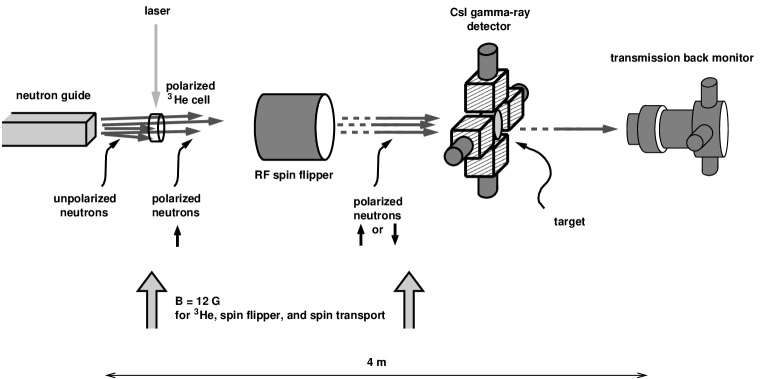
This section describes the apparatus used in Fall 2000 to measure directional asymmetries in gamma-ray emission following polarized cold neutron capture on nuclear targets. A schematic picture of the setup is shown in Fig. 1.
2.1 Pulsed Cold Neutron Beam
The LANSCE linear accelerator provides 800 MeV protons to a proton storage ring, which after compression of the beam delivers 250 ns wide (at the base) pulses at 20 Hz to a split tungsten spallation target. The downstream target is surrounded by several moderators, including a partially coupled cold hydrogen moderator viewed by Flight Path 11A (FP11A). The performance of the moderator is modeled in [13]. The neutron flux is directed through FP11A by a 58Ni-coated cm2 guide which begins 1 m from the moderator and is 18.5 m long. On the scale of 50 ms between pulses, the proton pulse width is very short and thus has an insignificant effect on the width of the neutron pulse from the moderator. An experiment located m from the source will see a time of flight spectrum of cold neutrons: for the typical energies of interest (1–100 meV, 1–9 Å) neutrons will arrive 4.5–45 ms after the proton pulse. Knowledge of time of flight and the flight path length determines the neutron energy.
2.2 Measurement of Cold Neutron Flux
An absolute measurement of the cold neutron flux was made by tightly collimating the beam with a 4 mm diameter Gd foil collimator. The collimator was placed in a shielding assembly 15 cm from the end of the guide. A 4.1 mm diameter 6Li-loaded glass scintillator was mounted on a photomultiplier tube which was itself mounted in an x-y positioner. This detector was located 2.65 m from the end of the guide. The collimation reduced the neutron rate enough to permit normal pulse counting techniques (to less than 60 kHz for energies less than 15 meV). With incident proton current of 90 A, the peak neutron flux out of the end of the uncollimated FP11A guide was neutrons/ms per pulse at 8 meV, and the total flux from 2.5 to 40 meV was neutrons per pulse. (Over the same energy range, including collimation to 5 cm diameter and transmission through the polarizer, there were neutrons/pulse incident on the target for the asymmetry measurements discussed below.) Using the geometry of the flight path and the collimation to convert from the measured rates, the result was a measured peak moderator brightness of neutrons/cm2/s/sr/meV/A at 4 meV, which is 20% lower than predicted by [13]. While the new FP12 is predicted to have a 50% larger brightness than FP11A [14], scaling by the measured FP11A flux indicates that FP12 will only be sufficient for the full NPDGamma experiment to make a raw asymmetry measurement of per neutron pulse. This corresponds to a physics asymmetry measurement of per pulse. Thus in the planned run time of three six month run cycles, where a run cycle consists of 2500 hours of 120 A proton beam, the predicted sensitivity of the experiment to is at the level of (30% of the DDH prediction [3]).
2.3 Intensity Fluctuations
Several possible processes, such as density fluctuations in the moderator or position fluctuation of the proton beam striking the tungsten spallation target, can produce pulse-to-pulse position fluctuations of the neutron beam which will induce noise in the asymmetry measurement that is greater than the counting statistics of the experiment. For the NPDGamma experiment, noise sources must be negligible compared to neutron counting statistics. A simple Monte Carlo study of intensity-induced position fluctuations of the neutron beam showed that relative intensity fluctuations with a variance of lead to noise in the asymmetry measurement equal to neutron counting statistics. Three sets of measurements were made of correlations between a proton current toroid monitor and a 3He ion chamber neutron flux monitor. The neutron intensity fluctuations for constant incident proton current were for each set of measurements, an order of magnitude better than the requirement. These measurements of the intensity fluctuations of the beam for constant proton current incident on the spallation target show that density fluctuations or bubbles in the cold hydrogen moderator were not a problem for the asymmetry measurements in this engineering run, and will not be a problem for NPDGamma.
2.4 3He Spin Filter
Cold neutron beams can be polarized in several ways, but the best technology for NPDGamma is a 3He spin filter [15]. 3He spin filters are compact, possess a large phase space acceptance, and produce a negligible fraction of capture gamma-ray background. In contrast to a polarizing supermirror, a 3He spin filter does not require strong magnetic fields or produce field gradients. This is important for the control of systematic errors in the NPDGamma measurement. The direction of the neutron beam motion due to Stern-Gerlach steering in a magnetic field gradient is correlated with the neutron spin direction and can therefore lead to a false asymmetry due to the solid angle change of the capture gamma-ray distribution in the target as seen by the gamma-ray detectors. For this engineering run a system with a double-chambered glass cell was used to contain the 3He. The cell also contained a small amount of Rb and N2. The 3He was polarized by spin-exchange optical pumping. The polarization of the 3He proceeds by optically pumping the 795 nm transition for the Rb valence electron, which transfers its spin to the 3He nucleus by a hyperfine interaction upon collision. The cross section for cold neutron absorption by 3He is essentially zero for parallel neutron and nuclear spins, but due to a large spin zero resonance in 4He, there is a large absorption cross section for anti-parallel spins. Thus a polarized volume of 3He can filter out one spin state of an unpolarized neutron beam and produce large neutron polarizations. The thickness of the spin filter can be optimized for polarization versus transmission.
A 12 G holding field was used to provide a uniform field parallel to the polarization direction and to prevent depolarization of the 3He by diffusion in transverse magnetic field gradients. Circularly polarized 795 nm laser light for electronic polarization of the Rb was provided by two 15 W laser diode arrays. One chamber of the cell, the pumping chamber, was in a small oven which was kept at 175 ∘C to control Rb vapor density, and this part was illuminated by the diode lasers; the other part of the cell, the polarizer, was the volume placed in the neutron beam and used to filter out the undesired polarization state. The polarizer chamber as seen by the neutron beam was circular, 7 cm in diameter, and 1.6 cm thick. Both upstream and downstream surfaces were concave with respect to the beam direction, in order to provide a uniform cell length to the beam while maintaining curved surfaces to prevent cell explosion. The polarizer chamber was connected by a 1 cm long glass feedthrough tube to the roughly spherical and 6 cm diameter pumping chamber.
The absolute neutron polarization was measured using a supermirror [16] and an ion chamber back monitor (discussed below), and the 3He polarization direction was reversed using an NMR adiabatic fast passage spin flip. Relative measurements of the 3He polarization were performed during data taking by an NMR system. Since in the test run it was discovered that the stray magnetic fields from the supermirror polarization analyzer interfered with the operation of the neutron spin rotator, the experiment will use a polarized 3He neutron polarization analyzer instead.
Measured neutron polarization varied from to for neutron energies of 10 meV to 2 meV, shown in Fig. 2. The neutron polarization is given by where is the number density of 3He, kb, is neutron energy in meV, is the length of the polarizer volume, and is the 3He polarization. At typical operating temperature, the 6.0 atm cm polarizer section of this cell had 3He polarization of . The relative error on the neutron polarization is 2%, a combination of three roughly equal sources of error from knowledge of the supermirror analyzing power, absolute accuracy of the NMR system, and statistical spread of individual NMR measurements.
2.5 Spin Flipper
To isolate a small parity-violating asymmetry, a common technique is to reverse the polarization of the incident beam and observe a correlated change in the direction of emission of the reaction products. For NPDGamma and for this test run, the neutron spins are flipped on a 20 Hz pulse-by-pulse basis with a radio frequency spin rotator, or spin flipper (RFSF). The RFSF is a shielded solenoid, 30 cm in diameter and 30 cm long, with the aluminum shielding canister a total of 10 cm larger in each dimension. The windows encountered by the neutron beam are 2 mm thick. The RFSF is similar to that employed in [17] with two modifications: the aluminum shielding, and the amplitude of the RF field is ramped down with an inverse time dependence every pulse to match the time the neutrons spend traversing the length of the coil.
The RFSF operates according to the well-known principles of NMR. In the presence of a homogeneous DC magnetic field and an oscillating magnetic field in a perpendicular direction, the neutron spin will precess [18]. For a DC field of and an RF field given by , transforming into a frame which rotates (at the same frequency as the oscillating field) about the DC magnetic field direction, the effective field is
| (1) |
where Hz/T is the neutron gyromagnetic ratio. For , a neutron initially polarized along will precess about the effective field direction . If the RF field is applied for a time equal to then the neutron spin direction will be reversed relative to .
The RFSF limits the region of the RF field along the neutron beam line by placing the RF coil inside of a cylindrical aluminum shield. The RF coil is a solenoid with its axis aligned along the neutron beam direction . For neutrons from a spallation source and a RF interaction region of fixed length , the interaction time is determined by the neutron velocity . The time will increase with increasing time of flight and obey the relationship
| (2) |
where is the length of the RFSF, and is the distance from the spallation neutron source to the RFSF. To produce a spin flip (), the RF amplitude must obey the relationship
| (3) |
In practice, the RF amplitude is not constant inside the RFSF since the normal component of the field must go to zero at the endcaps. Instead, it is the integral of the RF magnetic field amplitude along the length of the RFSF which must vary inversely with time to meet the spin flip condition for all of the neutron energies.
This type of spin rotator is an ideal choice for the NPDGamma experiment for a number of reasons. First, the spin flip can be performed on a pulse-by-pulse basis by simply turning the RF field on and off. Second, since one can contain the RF magnetic fields in metallic windows that are transparent to neutrons and the gain of the CsI detectors with vacuum photodiodes is relatively insensitive to DC and AC magnetic fields, couplings of the RF signal into the data stream which could lead to false asymmetries are greatly minimized. Third, no extra static magnetic fields or field gradients beyond those required for neutron spin transport are required. Fourth, the RFSF provides efficient pulse-to-pulse control of neutron polarization state for a wide range of energies. Fifth, and finally, this type of spin flipper does not change the neutron beam phase space or kinetic energy. Although a neutron will absorb or emit energy due to the external RF magnetic field, on resonance this change in energy is balanced by the change in potential energy of the neutron in the static magnetic field and the neutron kinetic energy does not change [19]. Therefore a host of possible systematic effects associated with a spin-dependent neutron energy spectrum of the beam are absent.
The RFSF field amplitude and frequency were tuned using the polarized neutron beam produced by the 3He system and a supermirror analyzer [16] to analyze the flipped pulses. The supermirror analyzer uses the spin dependence of the reflection probability of polarized neutrons from the neutron optical potential of magnetized mirrors to analyze the polarization with an analyzing power approaching 100% for cold neutrons.
The 3He/H2 ion chamber back monitor was placed downstream of the supermirror and the difference it recorded between RFSF on and off pulses yielded the RFSF efficiency. The RFSF was typically driven at 34 kHz in the holding field of 12 G, a relationship determined by the neutron gyromagnetic ratio. For a 2.5 cm collimated beam, the RFSF efficiency, defined as the absolute ratio of transmitted (flipped) neutron polarization to incident polarization, was measured to be . This efficiency is sufficiently large and well-known for NPDGamma.
2.6 Beam Monitors
Two current-mode beam monitors were used in this test run: a front monitor with 3He and 4He, and a back monitor with 3He and H2. The design of the front monitor allows it to employ an analog subtraction between the current signal of the 3He-filled front chamber (which responds to neutrons and gamma-rays) and the current signal from the 4He-filled rear chamber (which responds only to gamma-rays since the neutron absorption cross section of 4He is zero) to produce a signal which is dominated by neutron capture in the monitor [20]. As discussed above, the front monitor was used to measure fluctuations in beam intensity. It was then removed from the beamline for the measurements of gamma-ray asymmetries.
The back monitor, which is a 3He-filled segmented ion chamber similar in design to [21], was used to study the 3He spin filter system and the RFSF. It consists of a metal cylinder coaxial with the neutron beam with longitudinal segments bounded alternately by high voltage electrodes and signal collection plate electrodes. The chamber housed ten 7.6 cm diameter, 0.76 mm thick Al collection plates spaced evenly by 2.5 cm increments along the beam axis, and ten electrodes held at 3 kV. The voltage as a function of depth along the beam axis makes a zigzag pattern, with ions on either side of a high voltage plate accelerated to opposite signal plates. The detector is therefore effectively segmented into separate regions of sensitivity along the beam axis. This segmentation along with the known neutron absorption and scattering cross sections implies that the neutron signal changes in a known way as the neutron energy spectrum hardens as it passes into the chamber. A gas mixture of 0.5 atm 3He and 3 atm H2 was chosen based on simulations of the ion chamber response. H2 gas was chosen as the fill gas due to its low sensitivity to gamma-rays and the order-of-magnitude greater mobility of ions in H2 gas relative to other gases. This choice led to a collection time for the ions of about 100 microseconds. The 3He gas pressure and overall length of the chamber was chosen to produce an essentially unit neutron detection efficiency from 1–100 meV. If the detector efficiency is flat and the ion chamber signal is dominated by neutron capture, the observed current is proportional to neutron flux.
The depth dependence of the signal was consistent with expectations based on the assumption that the current mode signal was due to neutron capture. The sensitivity of the ion chamber to gamma-rays was measured by converting the entire neutron beam into 0.5 MeV gamma-rays directly in front of the chamber by absorption by the 10B in B4C. This test demonstrated that less than 0.3% of the signal was due to gamma-rays in the neutron beam. The neutron current measured by the ion chamber shows discontinuities which correspond to the presence of Bragg edges from the aluminum material in the beam. These discontinuities correspond to neutron wavelengths below which diffraction from those lattice planes separated by are forbidden. The relative time of flight positions of these Bragg edges in combination with the known source-chamber distance and the known spacings of aluminum are used to calibrate the time of flight spectrum in terms of neutron energy. Materials of the chamber were chosen to be high voltage compatible and bakeable to remove electronegative impurities and improve the ion drift velocity. The signals from the collection plates were read out to current to voltage amplifiers similar to those used for the CsI detectors with a 100 M gain resistor.
2.7 Nuclear Targets
For parity-violating and parity-allowed asymmetry measurements, three targets were used. As a chlorine target, an aluminum canister was filled with CCl4 (natural Cl). The CCl4 thickness seen by the neutron beam was 3.8 cm. As a lanthanum target, a natural La (99.91% 139La) metal cylinder 10.2 cm in diameter and 2.5 cm thick was housed in a 1 mm thick stainless steel can. As a cadmium target, a 0.76 mm thick piece of natural Cd metal was cut into a 10.2 cm diameter circle. To eliminate neutron backgrounds and reduce activation of the CsI(Tl), the targets were in turn mounted in a cylinder of 6Li-doped plastic with inner diameter 10.2 cm and outer diameter 15.2 cm. The neutron beam was collimated to 5 cm diameter and no neutrons were directly incident on the plastic cylinder. The targets were located at a flight path length of 21.9 m.
2.8 Gamma-ray Detectors
To detect the gamma-rays emitted following neutron capture, an array of four CsI(Tl) crystals was symmetrically mounted around the target volume. The crystals were housed in Al canisters with external dimensions cm3. The closest faces of the detectors were 8.4 cm from the central axis of the neutron beam, allowing each detector to cover a solid angle of sr with respect to the target location. The crystals were viewed with 70 mm vacuum photodiodes (Hamamatsu R2046PT) biased at -90 V. The photoelectron yield of the crystals was measured to be p.e./MeV, and typical photodiode currents were a few nA. This light output was sufficient to make the extra noise encountered in current mode measurement due to fluctuations in the number of quanta produced per neutron capture small compared to neutron counting statistics.
The magnetic field sensitivity of the photodiode signals to DC fields was measured to be less than /G in a 10 G field directed perpendicular to the photodiode axis. The second-order magnetic field sensitivity of the photodiode signals was measured to be less than /G2, in an oscillating field with amplitude of 10 G. For this engineering run and for the NPDGamma experiment, the RFSF magnetic field is the field with the most possibility for undesired experimental effects, as its presence or absence is by definition correlated with the neutron spin state. Since the RFSF magnetic field is not DC but operates at 30 kHz, a fast time scale compared to the recorded data, first order gain effects will cancel out, but second order effects may not. The measured sensitivities combined with the fields and field variations expected in the NPDGamma experiment lead to negligible systematic effects.
The current signals from the photodiodes were read out into a low-noise solid state current to voltage preamplifier with a gain resistor of 10 M. The preamplifier signals were sampled at 25 kHz with 16 bit ADC’s in a VME system, and the data compressed by a factor of ten to be written as 100 samples, or time bins, over 40 ms per pulse. With the neutron beam off, the r.m.s. noise per time bin was measured to be of order 1 mV. Pedestal values for the detectors were typically 100 ADC counts, or 30 mV. An average gamma-ray intensity spectrum, indicative of the time structure of the neutron flux, is shown in Fig. 3.
3 Asymmetry Measurements
Asymmetry measurements were made on three targets. The neutron energy range analyzed in each case was 2.5 meV to 40 meV, corresponding to 8–32 ms time of flight, or 1.4–5.7 Å.
Asymmetries were formed using matched eight-step spin sequences () of consecutive pulses and a calculation of the geometric mean asymmetry within the sequence. This 8-step sequence is chosen to cancel linear and quadratic time-dependent drifts in detector efficiencies. The raw experimental asymmetries are calculated as follows:
| (4) |
where refer to the upper and lower detector signals, and the subscripts refer to the neutron spin direction. For these measurements the up-down direction was the axis of the neutron polarization, so an asymmetry between the and detectors is parity-violating. An asymmetry between the and detectors is parity-allowed. The state corresponds to RFSF on, to RFSF off. The asymmetry was calculated for each valid eight-step spin sequence, in each case four steps added together to obtain and and the other four to obtain and . For each sequence the raw asymmetries were calculated by time bin using the data from the 20th to 80th of the 100 samples. This range in neutron time of flight corresponds to the peak of the neutron distribution and to a region of well-understood neutron polarization and RFSF efficiency. An identical procedure was used for the left and right detector pair. A cut was made to eliminate sequences which had pulses with anomalous incident neutron fluxes. If any of the eight steps had a detector sum () over all time bins that differed by more than 1% from the average of all the sequences in the sum, the entire eight-step sequence was discarded. This cut removed less than 1% of the data. The final data set for each target consisted of 6.5 to eight-step sequences.
For each sequence, the measured asymmetries were corrected to physics asymmetries in each time bin using
| (5) |
where is a measured false asymmetry due to electronic noise pickup, is the neutron polarization, is the RFSF efficiency, is a factor for neutron depolarization in the target prior to capture, and is a geometry factor for the average angle of the gamma-rays seen by the detectors relative to the neutron polarization. These factors are discussed in the following five paragraphs. The factors and vary with neutron energy, while the others are independent of the neutron energy (constant for all time bins). The data were combined in this way in order to obtain the proper weighting of events at different energies.
The electronic noise asymmetry was measured before and after the neutron capture data were acquired. With no neutrons incident on the apparatus, the average of two one-hour runs was and . These values were extracted from the data using the same method as for . Since these values are less than two standard deviations from zero and are an order of magnitude smaller than the statistical error, is used to obtain physics asymmetries from the raw asymmetries.
The absolute neutron polarization was measured using the supermirror analyzer and back monitor neutron detector, and fit to a hyperbolic tangent function to relate the pickup coil NMR signal to . NMR measurements were made during data taking and the NMR signal amplitudes measured during data taking with each target were used to provide a for the hyperbolic tangent expression given earlier for neutron polarization versus energy. The convolution of the neutron polarization values and the detector signals (versus energy) leads to an event weighted average polarization of for each of the targets.
Since the RFSF is on for half the neutron pulses, the measured efficiency yields a factor of for converting to a physics asymmetry.
Neutron depolarization in the target, , is accounted for using cross section values for (), spin-coherent scattering, and spin-incoherent scattering, taken from [22]. A simple Monte Carlo was written to propagate neutrons through the target material according to the cross sections (assuming a dependence of the capture cross section for 35Cl and 139La), and upon each scattering event the probability of spin-flip scattering was accounted for by taking the ratio of of the spin-incoherent scattering cross section to the total scattering cross section. Depolarization was determined by computing an average value for where was the number of spin-flip scatterings prior to capture. The convolution of the depolarization values with the detector signals leads to event weighted factors of for Cl, Cd, and La respectively. For each target, it was assumed that isotopes other than the one of interest (35Cl, 113Cd, and 139La) contribute negligibly to the scattering, capture, or .
The geometrical acceptance of the detector crystals was modeled using the computer code MCNP [23]. The result for average for parity-violating (up-down) asymmetry and for average for the parity-allowed (left-right) asymmetry yielded factors of for Cl, Cd, and La respectively. The angle is that between the neutron polarization axis and the gamma-ray momentum.
Following the above analysis, each sequence produced a result for parity-violating and parity-allowed , corresponding to and , where is the neutron spin direction, is the neutron momentum vector, and is the photon momentum vector. A histogram of the values of 35Cl , with one entry per sequence, is shown in Fig. 4. The physics asymmetries for each target were histogrammed and fit by minimizing compared to a Gaussian distribution to extract the mean value and the error in the mean. The results of the fitting are consistent with the simple average of each data set. For final results, the values for and are obtained from taking the list of sequence asymmetry values and calculating the mean and error in the mean from the simple average and standard deviation of the data. The signs of the asymmetries were carefully checked through the data acquisition electronics and analysis code.
Parity-violating asymmetries were detected (greater than two standard deviations from zero) in neutron capture on the Cl and La targets. No parity-allowed asymmetry was seen in those targets. No asymmetry of either type was observed with the Cd target. The results are presented in Table 1. The table includes: values , which are the raw asymmetry data over the analyzed energy range combined by weighting by number of events; values which are obtained from converting the raw asymmetries to physics asymmetries for each time bin, and then combining the results weighted by the error on the physics asymmetry in each bin; and previous results [9, 10].
The statistical error in the combined parity-violating Cl raw asymmetry data is . A calculation of the statistical error based on the number of neutron capture events results in an expected error of . The primary sources of uncertainty in this calculation are uncertainty in the neutron flux and in the effective solid angle of the detectors. The statistical errors on the asymmetries follow the expectation of counting statistics given the measured neutron flux and there is no evidence for extra noise sources. Systematic errors are small on the correction factors discussed above: 1% on , 2% on , 2% on , and 5% on . Studies which split the data into independent sets to compare asymmetry results discovered no anomalous effects.
A theoretical estimation of the parity-violating correlation in polarized cold neutron capture on 35Cl gives [24], which is consistent with experiment in both sign and magnitude. This estimate used the detailed knowledge of the spectroscopy of 36Cl, including the sign cancellations in the integral asymmetry from the many different transitions in the 36Cl de-excitation spectrum and the gamma-ray energy weighting appropriate for the current-mode asymmetry measured in this experiment.
4 Summary and Prospects
The parity-violating neutron capture asymmetry measurements reported here are consistent with previous experimental results [9, 10] and of somewhat comparable precision. However, they were made in a fraction of the run time (eight hours per target) due to the large flux available with the pulsed beamline at LANSCE. In the experiment the parity-violating asymmetry in 35Cl will be used to periodically monitor the performance of the apparatus.
No parity-allowed asymmetries were seen in these measurements, at the level of . A large parity-allowed (left-right) asymmetry would provide a useful technique for alignment of the NPDGamma detector array by observing the mixing of the known left-right asymmetry into the up-down detector channels. This alignment is required to suppress the size of systematic effects which lead to neutron spin-dependent left-right motion of the beam and/or intensity of the gamma-ray angular distribution. Another possible method to measure the angle of each detector element to 20 mrad precision would be to scan a small neutron capture target in x-y and observe the change in detected gamma-ray intensity. However, to remove the variable of beam non-uniformity, a method using translation of the array (rather than translation of a capture target) will be used for the full NPDGamma experiment.
This engineering run, as compared to the full apparatus that will be constructed for the NPDGamma experiment, was missing the following components: a frame overlap chopper, a full-sized 3He system, a liquid para-hydrogen target, a full complement of detectors, and a 3He neutron polarization analyzer. A new beamline at LANSCE for nuclear physics is under construction with a larger ( cm2 vs. cm2) supermirror guide. Scaling of the engineering run errors by run time, proton current, moderator brightness, guide characteristics of size and transmission, and detector solid angle, yields an expected statistical error on a statistics limited measurement of for of in 7500 hours of delivered neutron beam on FP12 at LANSCE. All tests show that the experimental design and method are sufficient to make a measurement of this precision for NPDGamma.
5 Acknowledgments
The authors would like to thank Mr. G. Peralta and Dr. J.M. O’Donnell for their technical support during this experiment. This work was supported in part by the U.S. Department of Energy (Office of Energy Research, under Contract W-7405-ENG-36), the National Science Foundation (Grant No. PHY-0100348), and the Natural Sciences and Engineering Research Council of Canada.
References
- [1] W. M. Snow et al., Nucl. Instr. and Meth. A 440 (2000) 729.
- [2] W. M. Snow et al., Nucl. Instr. and Meth. A 515 (2003) 563.
- [3] B. Desplanques, J.F. Donoghue, B.R. Holstein, Ann. Phys. 124 (1980) 449.
- [4] E.G. Adelberger, W.C. Haxton, Annu. Rev. Nucl. Part. Sci. 35 (1985) 501.
- [5] W. Haeberli, B.R. Holstein, in Symmetries and Fundamental Interactions in Nuclei, edited by W.C. Haxton, E.M. Henley, pp. 17-66, World Scientific, Singapore, 1995.
- [6] W.S. Wilburn, J.D. Bowman, Phys. Rev. C 57 (1998) 3425.
- [7] A. Csoto, B.F. Gibson, G.L. Payne, Phys. Rev. C 56 (1997) 631.
- [8] V.V. Flambaum, O.P. Sushkov, Nucl. Phys. A 435 (1985) 352.
- [9] V.A. Vesna et al., JETP Lett. 36 (1982) 209.
- [10] M. Avenier et al., Nucl. Phys. A 436 (1985) 83.
- [11] V.W. Yuan et al., Phys. Rev. C 44 (1991) 2187.
- [12] G.E. Mitchell, J.D. Bowman, S.I. Penttilä, E.I. Sharapov, Phys. Rep. 354 (2001) 157.
- [13] P.D. Ferguson, G.J. Russell, E.J. Pitcher, ‘Reference Moderator Calculated Performance for the LANSCE Upgrade Project,’ ICANS-XIII (1995); G. Muhrer, P.D. Ferguson, G.J. Russell, E.J. Pitcher, ‘As-Built Monte Carlo Model of the Lujan Target System and Comparison of its Neutronic Performance to a Physics Model,’ LANL Report LA-UR-00-6078 (2000); J.B. Donahue et al., ‘LANSCE Short-Pulse Spallation Source Target Upgrade,’ Proceedings of the 1997 Particle Accelerator Conference Vancouver, BC, Canada, May 12-16, 1997, 1:190-192, IEEE, Piscataway, NJ, 1998.
- [14] The brightness of the FP12 moderator has been measured by the NPDGamma collaboration. The peak brightness is neutrons/cm2/s/sr/meV/A at 3.3 meV. (P.-N. Seo et al., accepted for publication in Nucl. Instr. and Meth. A.)
- [15] G.L. Jones et al., Nucl. Instr. and Meth. A 440 (2000) 772; D.R. Rich et al., Nucl. Instr. and Meth. A 481 (2002) 431.
- [16] O. Schaerpf, Physica B 156 & 157 (1989) 631; O. Schaerpf, Physica B 156 & 157 (1989) 639.
- [17] L.W. Alvarez, F. Bloch, Phys. Rev. 57 (1940) 111.
- [18] A. Abragam, Principles of Nuclear Magnetism, Oxford University Press, Oxford, England, 1961.
- [19] R. Golub, R. Gähler, T. Keller, Am. J. Phys. 62 (1994) 779.
- [20] J.J. Szymanski et al., Nucl. Instr. and Meth. A 340 (1994) 564.
- [21] S.D. Penn et al., Nucl. Instr. and Meth. A 457 (2001) 332.
-
[22]
V.F. Sears, Neutron News 3 (1992) 29.
Table available at:
http://www.ncnr.nist.gov/resources/n-lengths/list.html. - [23] Code available from Radiation Safety Information Computational Center, Oak Ridge National Laboratory, as code package CCC-701 and data library DLC-200. See http://www-rsicc.ornl.gov/rsic.html.
- [24] V.E. Bunakov et al., Sov. J. Nucl. Phys. 40 (1984) 119. [Yad. Fiz. 40 (1984) 188.]