WECT003 READOUT AND CONTROL OF A POWER-RECYCLED INTERFEROMETRIC GRAVITATIONAL WAVE ANTENNA ††thanks: Work supported by National Science Foundation cooperative agreement PHY-9210038
Abstract
Interferometric gravitational wave antennas are based on Michelson interferometers whose sensitivity to small differential length changes has been enhanced by adding multiple coupled optical resonators. The use of optical cavities is essential for reaching the required sensitivity, but sets challenges for the control system which must maintain the cavities near resonance. The goal for the strain sensitivity of the Laser Interferometer Gravitational-wave Observatory (LIGO) is rms, integrated over a Hz bandwidth centered at Hz. We present the major design features of the LIGO length and frequency sensing and control system which will hold the differential length to within m of the operating point. We also highlight the restrictions imposed by couplings of noise into the gravitational wave readout signal and the required immunity against them.
1 INTRODUCTION
The interferometric gravitational wave detectors currently under construction by LIGO[1], VIRGO[2], GEO[3] and TAMA[4] are expected to reach strain sensitivity levels of at 150 Hz over baselines of several hundred meters up to several kilometers[5]. To achieve this sensitivity all of these interferometers implement a Michelson laser interferometer enhanced by multiple coupled optical resonators[6, 7].
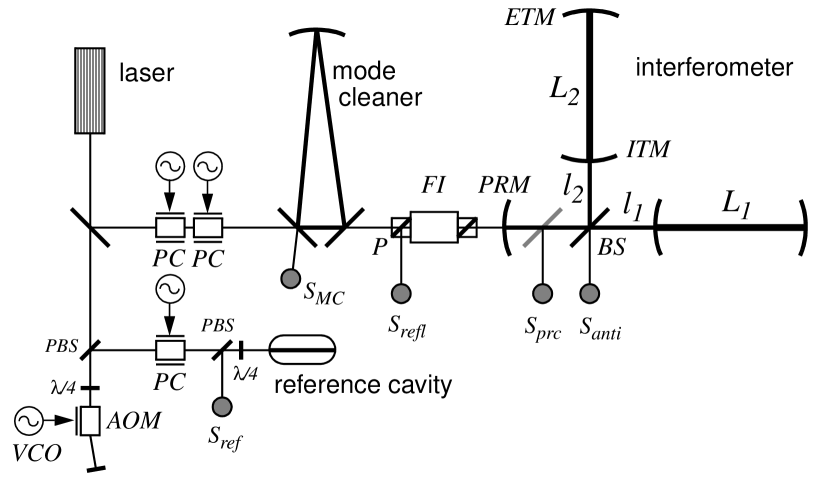
LIGO implements a power-recycled Michelson interferometer with Fabry-Perot arm cavities (see Fig. 1). Using optical cavities is essential in reaching the ultimate sensitivity goal but it requires an active electronic feedback system to keep them “on resonance”. The control system must keep the round-trip length of a cavity near an integer multiple of the laser wavelength so that light newly introduced into the cavity interferes constructively with light from previous round-trips. Under these conditions the light inside the cavity builds up and the cavity is said to be on resonance[8]. Attaining high power buildup in the arm cavities also requires that minimal light is allowed to leave the system through the antisymmetric port, so that all the light is sent back in the direction of the laser where it is reflected back into the system by the power recycling mirror. Hence, an additional feedback loop is needed to control the Michelson phase so that the antisymmetric port is set on a dark fringe.
2 Environmental Influences
It is important to distinguish low ( Hz) and high frequency behaviour of the instrument. The low frequency region is typically dominated by environmental influences many orders of magnitude larger than the designed sensitivity and in many cases also many orders of magnitude larger than what can be tolerated for stable operations. It is the high frequency regime which yields good sensitivity and which is used for detecting gravitational waves. To suppress low frequency disturbances many active feedback control systems are needed to compensate 4 longitudinal[9] and 14 angular[10] degrees-of-freedom in the main interferometer alone. Additional feedback compensation networks are needed to locally damp the suspended mirrors ( dofs), to control the mode cleaner (5 dofs) and to control the laser (2 dofs).
For example, seismic motion of the ground[13] is many orders of magnitude larger than the required gravitational wave sensitivity. In LIGO a multi-stage passive seismic isolation stack[11] together with a single-stage pendulum suspension system[12] is used to isolate the optical components from ground vibrations. This system system works well for frequencies above , but gives no suppression at frequencies of a Hz and below.
3 Feedback Compensation Network
In order to implement feedback each degree-of-freedom which is under control of the compensation network has to be measurable. LIGO implements the Pound-Drever-Hall reflection locking technique[14] to keep cavities on resonance and a variant of this technique is used to control the angular degrees-of-freedom[15]. These techniques work well near resonance where they behave linearly but have a strong non-linear behaviour far way from resonance giving no or misleading signals. The first step of engaging the feedback compensation network is to catch the system on resonance with a highly sophisticated computer code[16] running on a digital controls system.
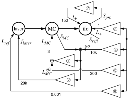
A schematic view of the length control system for the common mode degrees-of-freedom is shown in Fig. 2. The signal measuring the common arm length of the interferometer is fed back to a combination of test masses, mode cleaner length and laser frequency to achieve the required laser frequency noise suppression of in the frequency band of interest. To maintain maximum optical power in the system—and thus maximum signal to shot noise ratio—the control system must hold the common cavity length within of its resonance point. A similar but less complicated system is deployed to control the differential degrees-of-freedom. Their the differential arm cavity length has to be held within of its operating point to not pollute the gravitational wave signal with laser frequency noise.
4 Conclusions
So far LIGO has successfully demonstrated that the interferometer can be locked and kept on resonance for hours. The main goal in the near term is to improve the sensitivity which is still many orders of magnitude away from design, to engage the remaining feedback control paths and to fine-tune servo parameters.
References
- [1] A. Abramovici, W. Althouse, J. Camp, J.A. Giaime, A. Gillespie, S. Kawamura, A. Kuhnert, T. Lyons, F.J. Raab, R.L. Savage Jr., D. Shoemaker, L. Sievers, R. Spero, R. Vogt, R. Weiss, S. Whitcomb, and M. Zucker, “Improved sensitivity in a gravitational wave interferometer and implications for LIGO,” Phys. Lett. A218, 157–163 (1996).
- [2] B. Caron, A. Dominjon, C. Drezen, R. Flaminio, X. Grave, F. Marion, L. Massonnet, C. Mehmel, R. Morand, B. Mours, V. Sannibale, M. Yvert, D. Babusci, S. Bellucci, S. Candusso, G. Giordano, G. Matone, J.-M. Mackowski, L. Pinard, F. Barone, E. Calloni, L. DiFiore, M. Flagiello, F. Garuti, A. Grado, M. Longo, M. Lops, S. Marano, L. Milano, S. Solimeno, V. Brisson, F. Cavalier, M. Davier, P. Hello, P. Heusse, P. Mann, Y. Acker, M. Barsuglia, B. Bhawal, F. Bondu, A. Brillet, H. Heitmann, J.-M. Innocent, L. Latrach, C.N. Man, M. PhamTu, E. Tournier, M. Taubmann, J.-Y. Vinet, C. Boccara, P. Gleyzes, V. Loriette, J.-P. Roger, G. Cagnoli, L. Gammaitoni, J. Kovalik, F. Marchesoni, M. Punturo, M. Beccaria, M. Bernardini, E. Bougleux, S. Braccini, C. Bradaschia, G. Cella, A. Ciampa, E. Cuoco, G. Curci, R. DelFabbro, R. DeSalvo, A. DiVirgilio, D. Enard, I. Ferrante, F. Fidecaro, A. Giassi, A. Giazotto, L. Holloway, P. LaPenna, G. Losurdo, S. Mancini, M. Mazzoni, F. Palla, H.-B. Pan, D. Passuello, P. Pelfer, R. Poggiani, R. Stanga, A. Vicere, Z. Zhang, V. Ferrari, E. Majorana, P. Puppo, P. Rapagnani, and F. Ricci, “The VIRGO interferometer for gravitational wave detection,” Nucl. Phys. B54, 167–175 (1997).
- [3] K. Danzmann, “GEO 600 — A 600-m Laser Interferometric Gravitational Wave Antenna,” in First Edoardo Amaldi conference on gravitational wave experiments, E. Coccia, G. Pizella and F. Ronga, eds. (World Scientific, Singapore, 1995), p. 100–111.
- [4] K. Tsubono, “300-m Laser Interferometer Gravitational Wave Detector (TAMA300) in Japan,” in First Edoardo Amaldi conference on gravitational wave experiments, E. Coccia, G. Pizella and F. Ronga, eds. (World Scientific, Singapore, 1995), p. 112–114.
- [5] R. Weiss, “Electromagnetically coupled broadband gravitational antennae,” MIT Res. Lab. Electron. Q. Prog. Rep. 105, 54–76 (1972).
- [6] J.-Y. Vinet, B.J. Meers, C.N. Man, and A. Brillet, “Optimization of long-baseline optical interferometers for gravitational-wave detection,” Phys. Rev. D38, 433–447 (1988).
- [7] B.J. Meers, “The frequency response of interferometric gravitational wave detectors,” Phys. Lett. A142, 465–470 (1989).
- [8] A.E. Siegman, Lasers, (University Science, Mill Valley, Calif., 1986), Chap. 13, p. 663.
- [9] P. Fritschel, R. Bork, G. González, N. Mavalvala, D. Ouimette, H. Rong, D. Sigg, and M. Zucker, “Readout and control of a power-recycled interferometric gravitational wave antenna,” Appl. Opt. 40, 4988–4998 (2001).
- [10] P. Fritschel, G. González, N. Mavalvala, D. Shoemaker, D. Sigg, and M. Zucker, “Alignment of a long-baseline gravitational wave interferometer,” Appl. Opt. 37, 6734–6747 (1998).
- [11] J. Giaime, P. Saha, D. Shoemaker, and L. Sievers, “A passive vibration isolation stack for LIGO: design, modeling, and testing,” Rev. Sci. Instrum. 67, 208–214 (1996).
- [12] A. Gillespie and F. Raab, “Thermal noise in the test mass suspensions of a laser interferometer gravitational-wave detector prototype,” Phy. Lett. A178, 357–363 (1993).
- [13] T. Lay, and T.C. Wallace, Modern global seimology, (Academic Press, San Diego, California, 1995), p. 179.
- [14] R.W.P. Drever, J.L. Hall, F.V. Kowalski, J. Hough, G.M. Ford, A.J. Munley, and H. Ward, “Laser phase and frequency stabilization using an optical resonator,” Appl. Phys. B31, 97–105 (1983).
-
[15]
Y. Hefetz, N. Mavalvala, and D. Sigg, “Principles of calculating
alignment signals in complex optical interferometers,” J. Opt.
Soc. Am. B14, 1597–1605 (1997).
D. Sigg, and N. Mavalvala, “Principles of calculating the dynamical response of misaligned complex resonant optical interferometers,” J. Opt. Soc. Am. A17, 1642–1649 (2000). - [16] M. Evans, N. Mavalvala, P. Fritschel, R. Bork, R. Gustafson, W. Kells, M. Landry, D. Sigg, R. Weiss, S. Whitcomb, and H. Yamamoto, “Lock acqusition of a gravitational wave interferometer,” submitted to Opt. Lett. (2001).