WEAT002 RE-ENGINEERING OF THE GSI CONTROL SYSTEM
Abstract
After more than 12 years of operation without substantial revision a modernization of the control system at GSI is overdue. A strategy to adapt the system to future needs is outlined. The system has to support a specific environment of which the main features are described. More flexibility than in the current system can be achieved while still using many parts of the actual system.
1 INTRODUCTION
The actual GSI control system started operation in 1989. Many extensions and refinements have been developed since but no substantial revision could be made. As a result the system is outdated in many aspects. Only one environment is supported, one fieldbus, one type of device controller, one operating system for the applications. Hardware is no longer available, e.g. the controller boards from 1990, support for Pascal as programming language for the device control software ended.
Most components were developed to inhouse standards. Interfaces between components are too complex. Therefore exchange of single components is costly. A general revision is overdue. The modernization has to consider the characteristics of the GSI environment.
2 CONTROL ENVIRONMENT
2.1 GSI Accelerator Operation
GSI operates three accelerators for all kind of ions from hydrogen to uranium: The linear accelerator Unilac, the synchrotron SIS and the storage ring ESR. Linac and synchrotron are operated in a pulse to pulse time sharing mode with a repetition rate of 50 Hz of the linac and 0.1 to 0.5 Hz of the synchrotron. Switching to different ion species, energies, and experimental targets is done with this rate. Three independent ion sources serve in parallel typically five experiments at Unilac, SIS and ESR. The average duration of an experiment is one week.
In addition to this flexible experimental operation a rigid mode for heavy ion cancer therapy is provided [1]: Any carbon beam from a fixed set of 254 energies, 15 intensities, and 7 spot sizes will be delivered to the irradiation place by request.
2.2 Device Handling
Pulse to pulse switching demands a more complex device handling than simple schemes like ‘set reference’, ‘read actual value’. This can be illustrated with magnets in Unilac cycles for low-charged ions. One controller has to service up to 12 magnets in 20 ms cycles. Preset time has to be maximized to reach high currents, and stable current duration has to be limited to reduce thermal load.
Broadcasting a medium level set value at start of cycle gives slow devices time to reach full current. To avoid overheating of fast devices the dedicated set value is delayed for 4 ms. After end of beam all magnets have to be set to a zero value. The duration of stable currents is too short to read actual values directly. So ‘sample and holds’ are triggered for read-out. The controller can read these values not until in the following cycle reference values have been set.
2.3 Device Realization
In most cases the devices connected to the control system are rather complex. Some components are implemented as distinct parts like the extraction kicker with 28 modules. On the other hand some hardware components host several devices, e.g. profile grids. Up to 16 grids are distributed on 8 channels in one measuring device. Multiplexing restricts measurement to one channel per cycle. Nevertheless the variety of different implementations has to be presented in a comprehensive way to the operation crew. Grids have to appear as independent devices and the kicker modules have to be combined to one kicker.
3 ACTUAL CONTROL SYSTEM
3.1 Scheme of the control system
The hardware outline of the actual control system [2] is given in figure 1. The diagram reflects also the logical view since each module is rigidly connected to one of the hardware levels.

All devices are linked via field bus (modified MIL 1553) to distributed equipment controllers (EC). Synchronized operation is achieved by triggers from programmable central timing units, one for each accelerator. Supervisory controllers (SC) handle interaction with the operation level. One SC serves up to nine ECs.
Communication between EC and SC is done by dual ported RAM on the EC. SCs and workstations communicate via ethernet by an in-house protocol comparable to UDP/IP. VME boards with 68020 processors are used for ECs and SCs. Operation level workstations run OpenVMS.
3.2 Real-Time Control
The real-time level is the most substantial part of the GSI control system. Device interactions are triggered by signals from central timing units. Up to 255 different triggers allow flexible adaption to the accelerating process.
ECs run autonomously under control of the timing unit after device data have been supplied. Up to 16 different sets of data, called virtual accelerators, may be configured in parallel on the ECs. This enables pulse to pulse switching between as many different beams. Beams for cancer therapy are handled analogously [1].
The sequence of virtual accelerators is determined online by the timing units: Beam is produced only on request by the experimental area.
Execution of commands from the operation level is provided. Device interrupts and polling services for survey of the devices are supported.
3.3 Device Representation
The devices are represented in an object oriented manner as independent units even though the control system was developed in a procedural way. Unique device names, the so-called nomenclatures, facilitate addressing. Every property is modelled by an action, coded as a procedure on the SC, with data to be exchanged, e.g. sending a reference or reading an actual value. Properties are identified by name and described in a formalized way by type and count of corresponding data. Based on this description one single interface allows access to every property of every device.
To keep applications well structured nomenclatures represent independent objects with relevance for the process of acceleration. These logical devices are constituted on the real-time level: Every nomenclature must have a corresponding entry on the EC. Mapping of the connected hardware to the operations view is demanded.
4 UPGRADES
4.1 Strategy
Replacement of the control system by a different one would require a lot of effort. Existing devices and interfaces must be supported, the achieved quality of accelerator operation has to be provided, and existing control hardware has to be used further in order to reduce expenses.
Actually 2750 devices are controlled by 256 ECs in 41 VME crates. Device specific adaptions can be subsumed in 61 classes, each requiring its own handling. Implementation of device adaptions requires 145,000 lines of code (LOC) compared to 26,000 LOC for common system software. The effort needed to reimplement peculiarities could be seen when a functional prototype of the Unilac timing unit was rebuild. Although it provided less functionality than is implemented today, and work was done within the same environment, it took about one person year.
Fortunately the architecture of the existing control system is still up to date. Stepwise migration to a system similar to the actual one but providing greater flexibility is managable. This will result in a to date system and will allow to re-use most of spent investments.
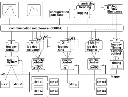
4.2 Outline of the Future Control System
The outline of the proposed future control system is shown in figure 2. It is still a three level approach: Device control engines, device representation by logical devices, and the application level. Different from figure 1 it is a logical view. Components can be installed on every hardware level of the control system.
4.3 Synchronized Device Control
Strong point in the existing control system is the real-time device control. It proved to be very well adapted to the needs of flexible pulse to pulse operation of the GSI accelerators. Therefore the same mechanism will be used in the future. This allows to utilize the existing generation and delivery of triggers for device synchronization.
Actions to service devices autonomously, under control of the timing system, are realized in synchronous device control engines. The actual EC software can serve as a first version of these engines. Fortunately most effort to implement device specific adaptions was on the EC, both in size and complexity.
4.4 Extensions for the Device Control Level
In many cases a synchronization with the accelerating cycle is not needed, e.g. for slow mechanical actuators. An asynchronous device control engine will be provided by reducing a synchronous engine to polling and service of device interrupts.
Real-time systems are difficult to survey and to debug. To keep the control engines simple any mapping between the hardware and the process view should be avoided here. E.g. the electronics for profile grids should be handled as one unit. Consequent reduction to the kernel functionality allows in many cases to describe device characteristics by simple tables. These devices then can be handled by one common software.
In the current EC software, the hardware dependent parts of code have to be identified to make the control engines portable. Implementation will be possible on any computer in the control system, on dedicated device controllers and on multi purpose computers. Nevertheless if good real-time performance is needed computers with a hard real-time system will be used.
4.5 Device Modelling Level
Object oriented approach suggests to represent connected hardware as objects, called logical devices. Device functionality in the sense of the actual control system then corresponds to methods of the logical device.
Dealing with various device specific methods can be confusing.
Therefore every logical device will have a common method as interface.
Variable data formats can be exchanged
by using types like CORBA’s any.
In IDL notation this method may look in principle like
void access(in string property, inout any data)
raises (ControlException);
Logical devices are suitable locations to map the accelerator hardware to logical devices oriented to the process. Different abstraction levels can be build by cascading. E.g. magnets and profile grids can be combined to emittance measurement devices. Any unit can be integrated as a logical device at this level: Complete subsystems like SCADA systems, devices with an OPC interface, or even software objects like databases.
A scheme for the logical devices has to be developed which is more general than in the actual system. Effort for implementation of device specific adaptions can be reduced by integrating code from the existing system. Procedures corresponding to properties can be transformed to objects’ methods. Header and exit part of the procedures have to be replaced but the body can be kept with slight modifications. This allows a fast integration of the existing implementations but of course can only be a first step. Modern software development technics allow much more elegant solutions compared to realisations in the actual system.
4.6 Networking
Communication with logical devices, distributed objects, is straightforward. Common middleware like CORBA based systems support all needs of accelerator operation. Naming services or alternatively explicit handling of object references allow addressing of logical devices by name.
4.7 Application Level
No detailed investigations have been made yet. OpenVMS and Unix are based on similar concepts. This suggest to use Linux as future basis for the application level.
In a transitional period both operation systems have to be supported in parallel. To allow further usage of existing applications the current interface for device access has to be provided in the future too.
4.8 Preparatory Work
The device control software was written in Pascal. Actual software development systems are now based on C++. To enable future usage of existing software conversion of the code to C has started [3].
Substantial changes of the actual system can easily impact the ongoing accelerator operation. To limit the implications of modifications the modularization has to be enhanced. In a re-engineering process each module in the control system has to be provided with structured interfaces to reduce coupling. Only after this it will be possible to replace existing components or port components to other platforms with acceptable effort.
5 CONCLUSION
The paper outlines a strategy for a rejuvenation of the existing control system. It shows the possibility to enhance flexibility and capacity of the system and nevertheless to integrate many parts of the existing system. The modernized control system will be suitable for the proposed new accelerator facilities too.
References
- [1] U. Krause, R. Steiner, “Adaption of a Synchrotron Control System for Heavy Ion Tumor Therapy”, Proceedings of ICALEPCS ’95, Chicago, USA, 1995
- [2] U. Krause, V. Schaa, R. Steiner, “The GSI Control System”, Proceedings of ICALEPCS ’91, Tsukuba, Japan, 1991.
- [3] L. Hechler, “Converting Equipment Control Software from Pascal to C/C++”, these proceedings.