Design study of an optical cavity for a future photon-collider at ILC
Abstract
Hard photons well above 100 GeV have to be generated in a future photon-collider which essentially will be based on the infrastructure of the planned International Linear Collider (ILC). The energy of near-infrared laser photons will be boosted by Compton backscattering against a high energy relativistic electron beam. For high effectiveness, a very powerful lasersystem is required that exceeds todays state-of-the-art capabilities. In this paper a design of an auxiliary passive cavity is discussed that resonantly enhances the peak-power of the laser. The properties and prospects of such a cavity are addressed on the basis of the specifications for the European TeV Energy Superconducting Linear Accelerator (TESLA) proposal. Those of the ILC are expected to be similar.
keywords:
linear collider, photon collider, Compton backscattering, power enhancement cavity, burst mode laser, High-power large-scale laser systemPACS:
41.75.Lx , 42.60.Da , 42.55.Vc , 29.25.-t , 13.60.FzDESY 05-098
11 July 2005
, , ,
1 Introduction
There is a worldwide consensus that the next particle physics project is a linear accelerator for positron-electron () collisions in the energy range of 500 GeV to 1 TeV[1]. In Summer of 2004 the International Committee for Future Accelerators (ICFA) recommended to the International Linear Collider Steering Committee (ILCSC) an accelerator based on superconducting radio frequency resonators for setting up the International Linear Collider (ILC) [2]. Such a technology has been developed by the TESLA (TeV Energy Superconducting Linear Accelerator) collaboration. Besides collisions between , a second interaction point (IP) for collisions between photons as well as collisions of electrons on photons is foreseen. This second IP is commonly referred to as the Gamma-Gamma () Collider arm of a linear collider. In this paper we will continue to use the parameters of the superconducting TESLA machine [3], as the parameters of the ILC are expected to be similar.
2 Creation and collision of high energy photons
In a photon collider two opposing pulsed electron beams of = 250 GeV energy travel towards the interaction point (IP). According to the architecture of the TESLA design each of them collides a few mm before the IP with a tightly focused laser beam. Its diameter is of the order of a few 10 m, which will be much larger than the elliptical cross section of the electron bunch size. The latter exhibits 88 nm and 4.3 nm in its two perpendicular half axes for TESLA [4]. The laser photons (eV) are backscattered as outlined in Fig. 1.
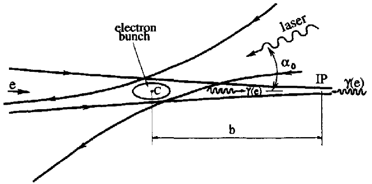
Compton scattering raises their energy close to that of the initial electrons. The produced propagate in the direction of flight path of the electrons. There is a small additional angular spread of the order of 2 rad, where (: electron mass, : speed of light in vacuum). Compton backscattering is the most promising process for efficient creation of highly polarized, beams in the range of several hundred GeV with low background [4, 5, 6, 7]. At the IP they collide with a similar opposite or electron beam. The photon spot size at the IP will then be almost equal to that of the electrons at the IP. Therefore the total luminosity of , collisions will be similar to that of the basic beams.
¿From kinematics the maximum photon energy is given by
| (1) |
, and denote the electron beam energy, photon energy and wavelength of the laser. represents the crossing angle between laser and electron beam. It is desirable to keep below 4.8, since for larger the high energy photons are lost by pair production due to their interaction with the laser beam [8]. For the TESLA beam parameters a wavelength near = m coinciding with powerful solid state lasers appears to be promising [4]. Then and = 207 GeV arise for a 250 GeV beam. The resulting Compton spectrum is strongly sensitive to the product of the mean electron helicity () and that of the laser photons (). A value close to , i.e. a circular polarized laser beam with opposite helicity as that of the electrons should be used to maximize luminosity at high photon energies [4].
The time structure of the laser system must match the bunch structure of the accelerator with 2820 bunches per train, each of 2.4 ps FWHM ( = 1 ps) duration for TESLA. The bunches are 337 ns apart and have a 5 Hz repetition rate [3, 4]. Pulses of several Joule are required to scatter the majority of electrons. The precise energy of each pulse depends strongly on the degree of focusing the optical onto the electron beam, as well as on the crossing angle in respect to the electrons. A Nd:YLF-based laser architecture generating this special time structure and providing a flat and stable train of ultraviolet (UV) synchronized ps pulses over 0.8 ms long time periods is already in use for some time at the TESLA Test Facility (TTF)[9, 10]. At a wavelength of 1047 nm it delivers J per pulse to the nonlinear crystals for conversion into the UV. At present, a maximum single pulse energy in excess of J for bursts containing 800 pulses at 1 MHz repetition rate, corresponding to 30 MW peak-power is generated in the infrared. For bursts of 2400 pulses this reduces to J per pulse at 3 MHz repetition rate within the pulse train [10]. This system produces an average power between one and two watts. On the other hand, current solid-state laser technology is clearly in the position of generating short pulses at the 5 TW peak-power level. In the foreseeable future however, the required high average power for a photon collider of several ten kilowatt and diffraction limited pulses can not be produced directly with the output from a laser [11, 12].
According to the TESLA machine parameters [4] each bunch contains electrons, whereas a 5 J Laser pulse at nm consists of photons. Provided that all electrons within the bunch undergo scattering, only one in photons is lost during a single laser-electron collision. Thus, it has been proposed to reuse the remaining laser pulse by storing it in a passive resonant optical cavity [13, 14, 15]. This results in a significant reduction of the required single pulse energy to be delivered by the laser. The time structure of the electron bunches as planned for TESLA is particularly well suited for application of such a cavity. Its round-trip time has to be adapted to the bunch-spacing of 337 ns resulting in a circumference of about 100 m. As will be shown, this is sufficient for wrapping the optical cavity around the particle detector.
3 Existing applications of passive optical cavities
Passive build-up cavities for generating a region of enhanced intensity are routinely used in combination with both continuous wave (cw) and mode-locked sources in a number of laser-related experiments such as frequency doubling [16, 17, 18, 19] (cw-laser), [20, 21, 22] (mode-locked laser), high-resolution spectroscopy [23, 24, 25, 26, 27], high sensitive detection of absorption [28, 29, 30, 31] or cavity ring-down absorption spectroscopy [32]. For the latter, linear cavities for micro-pulse energy enhancement in the mid-infrared region at 5.3 m have been investigated at the Stanford free-electron laser [33, 34].
A recent application is the amplification of ultrashort light pulses through phase coherent superposition of successive pulses from a mode-locked pulse train in a high-finesse optical cavity and subsequent cavity dumping [35, 36, 37]. An amplification factor in the order of 10 has been obtained.
For optical interferometric detection of gravitational waves a 2000-fold power recycling cavity for the GEO600-project, one of several current first-generation large-scale interferometers, is specified to develop a cw light power of approximately 10 kW within the interferometer [38]. Recently, a power enhancement in the range between 1000 and 1200 has already been obtained with approximately 5 W input from the mode cleaner cavities [39].
Laser increasingly enter also the field of high energy physics for monitoring the transverse size of electron beams (“laser wire”)[40, 41, 42, 43, 44, 45], as well as for precision measurement of electron beam polarization [46, 47, 48]. Both are based on Compton scattering of low energy photons around 1 eV. The ”laser wire” technique relies on an optical cavity for boosting the laser power.
Most of the current cavities for the purpose of frequency doubling have a ring configuration, providing optical isolation from the laser cavity. This advantage has been pointed out in [49]. The ring configuration is also the preferred geometry for an optical cavity for the photon collider.
Some non-resonant storage rings have been demonstrated in which the energy of a laser pulse that was lost through scattering, diffraction at the mirrors and upon impact with the electron beam is partially replaced by an amplifier [50, 51]. In these cases, the round-trip time of the optical pulse is less than the intervals of the laser pulses. These storage rings operate well below the power density required for the -collider.
4 Energy storage properties of the passive optical cavity
A short pulse is a wave packet with a wide frequency spectrum. One therefore has to pursue the transfer function approach, whereas the transient response of the circulating field strength within the cavity to the incoming TESLA burst-mode time structure is mathematically described by a convolution of the incoming laser pulses with the impulse response function of the cavity [52]:
| (2) |
Then is proportional to the circulating intra-cavity power and the incident power . := defines the enhancement factor of the cavity for the incoming power . For sake of simplicity we assume bursts of rectangular shaped laser pulses, each of duration , that are synchronous with the round-trip time of the cavity. Such a train of pulses is represented by a convolution of the function describing the characteristics of a single pulse with the sampling function:
As a consequence of the shifting property of the -function, the circulating field of the cavity from Eq. (2) is a sum of properly shifted and scaled replicas of the injected field . The convolution of Eq. (2) can however more conveniently be solved by taking the inverse Fourier transform of the intra-cavity spectrum . Then one benefits from the convolution property of the Fourier transform that states
| (4) |
The input spectrum of the burst from Eq. (4) according to the Fourier transform
| (5) |
results in
The transfer function for the power build-up ring cavity is almost identical to that of a Fabry-Perot interferometer. Extending the derivation described in [53] to a ring cavity with loss the transfer function can be expressed as
| (7) |
In the above equation repesents the amplitude of a monochromatic wave within the cavity at optical frequency that is due to a monochromatic input field at same frequency with unit amplitude. represents the intensity reflectivity of the coupling mirror and the power loss factor for one round-trip. The latter subsumes all loss mechanisms: intra-cavity absorption, diffraction and scattering as well as the finite reflectivity of all cavity mirrors with exception of the coupling mirror. and are related to the corresponding quantities for the field amplitudes (denoted with small letters) by
| (8) |
As stated in [53] the square modulus of the transfer function Eq. (7) gives the power response to a unit power monochromatic input field. This turns out to be the Airy shape function with Finesse as a parameter [54]:
| (9) |
| (10) |
The cavity field is maximized at the resonances of the cavity which occur if equals a positive integer number . In terms of the round-trip path length = and optical wavelength = with representing the speed of light in vacuum, the resonance condition is simply
| (11) |
The transfer function describes the evolution of the electric field at an arbitrarily chosen point within the cavity. in Eq. (7) it is located a propagation distance of behind the coupling mirror. This can be seen by the argument of the complex exponential in the numerator instead of for the complete revolution which appears in the denominator.
The above functions Eq. (4, 7) are combined to the intra-cavity spectrum = . By subsequent application of the inverse Fourier transform
| (12) |
one finally arrives at the intra-cavity-field
| (13) | |||||
Since , the identity
| (14) |
together with properties of the Fourier transform could be used in derivation of Eq. (13). Since , the round-trip time introduces a staircase behavior for the resulting intra-cavity power. Two regimes evolve from Eq. (13). The power builds up during the first revolutions of the pulse as long as energy is fed from the burst mode laser into the cavity (). When all laser pulses of the burst had been issued the stored power decays during the subsequent circulations ().
| (15) |
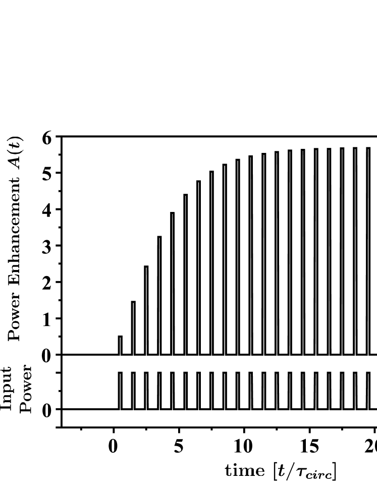
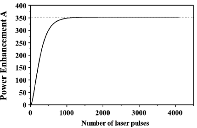
At resonance the enhancement of the incoming laser pulse power simplifies to
| (16) |
Fig. 2 shows the typical transient behavior of the power within the cavity according to Eq. (16).
For an uninterrupted pulse train () the enhancement factor at completion of round-trips converges to:
| (17) |
The same expression arises from a monochromatic, i.e. continuous wave. An efficient enhancement will require and close to one. Stationary conditions will then be reached to a very good approximation within each burst of the TESLA time structure.
Besides power reflectivities and losses the power enhancement is determined by the length detuning of the cavity. Any arbitrary circumference can be expressed as = with . From Eq. (15) follows then for sufficient large :
| (18) |
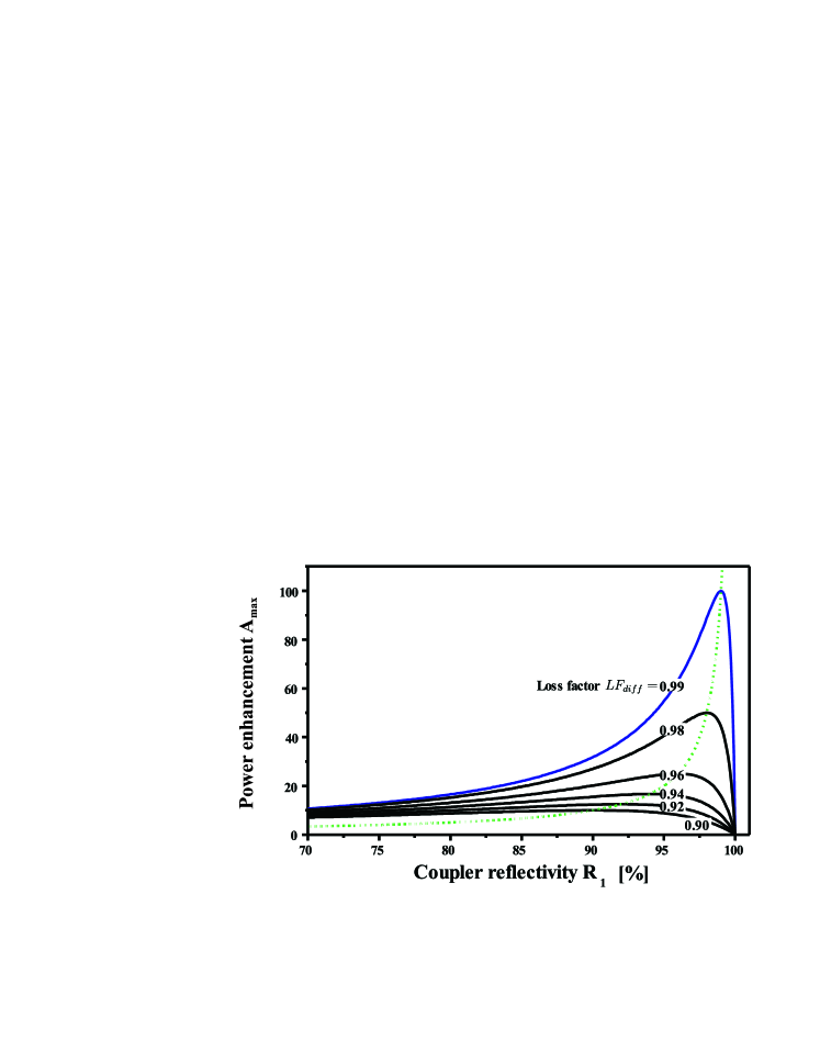
If the reflectivity of the coupling mirror equals a given loss factor , the power enhancement takes its maximum possible value and all light is absorbed by the resonant cavity. This is known as impedance matching () in analogy to properties of electrical cables and waveguides. In Fig. 3 the dependence of the enhancement factor on the input mirror reflectivity at different values of is plotted. Each curve shows a maximum value for equal to .
The resonant (), impedance-matched power enhancement can also be expressed in terms of the finesse given by
| (19) |
Hence, a Finesse in excess of 300 corresponds to an assumed example of = 100.
The duration for which a laser pulse will be stored within the cavity is given by the cavity photon lifetime . That is defined by the approximately exponential decay of the power following a sudden turn-off of the injected laser pulses at some time . Then turns out to be represented by
| (20) |
for the impedance matched cavity. A round-trip time of = 337 ns and = 100 result in 49.75337 ns 16.8 s. Using this result the effective number of round-trips of an optical pulse within the cavity is determined by
| (21) |
This number amounts to 50 in the above example.
It can be shown that for an uninterrupted pulse train the power that is reflected off an impedance matched cavity () declines as
| (22) |
No power will thus be reflected from an impedance matched cavity in steady state. This behavior can be used as an indicator for the alignment of the cavity in an automatic control system.
5 Constraints due to the particle detector and design proposal for an optical cavity
The Compton-interaction requires operation of the cavity in the Ultra High Vacuum (UHV) of the accelerator. When operated at the inevitable high power level optical windows within the cavity would imply the risk of distortion of the circulating optical ps-pulse as a result of the non-vanishing B-integral [55, 56]. For maintaining a sufficient high flux density and hence a luminosity of around cm-2 s-1, the laser pulse must be focused at the Compton conversion point (CP).
The particle detector for the -option is expected to be almost identical to the one for -physics located at the leptonic IP. For TESLA, the path length between its end face and the focus of both optical cavities amounts to about 7.40 m [57]. The end faces extend over 7.45 m and are perpendicular to the beam axis. As a consequence of the required tight optical focus, a widespread beam diameter of more than half a meter will emerge from the detector end-faces. Due to shortage of space any optics for the optical cavity should preferably be positioned outside the environment of the particle detector.
These demands suggest to employ two symmetrical telescopic ring cavities, required for Compton conversion at each of the counter-propagating electron beams, and to interlace them without mutual interference. Fig. 4 depicts an aerial view on two possible spatial embeddings of these cavities.
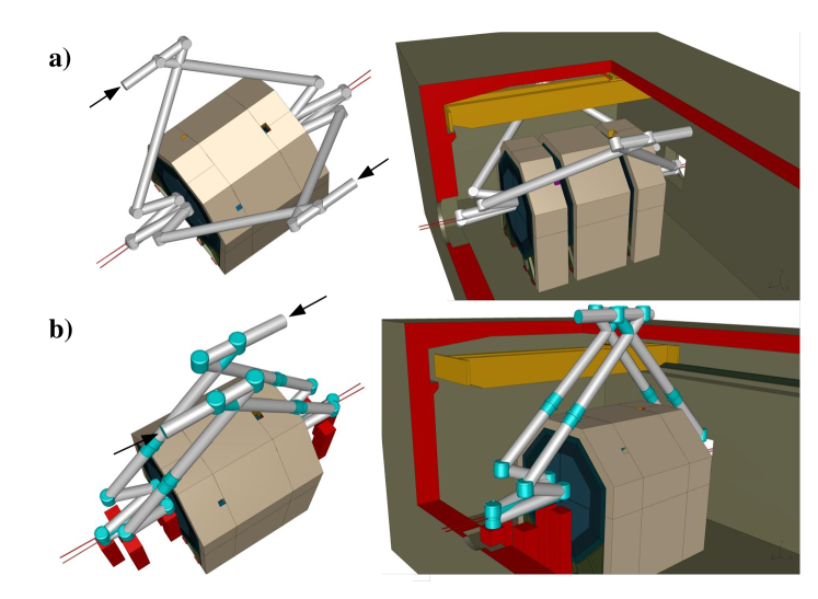
Their optical paths are enclosed within the associated optical beam pipes which are needed for maintaining the vacuum. In the upper sketch each ring resonator stretches across a plane. Both planes enclose an angle of degrees. This tipping allows an un-obstructed passage of both electron beams directions. In addition, a small tilt angle of approx. and , respec., in the vertical direction prevents the mirrors of the final focusing optics being to close to the leptonic beams. The two laser beams originate from a separate hall placed directly above the detector. They are pointing in opposing directions with the same vertical tilt for coupling into their respective cavities on top of the detector. For the lower design, the optical beam paths outside the detector are kept in two adjacent parallel planes. They cross each other in the interaction region within the detector.
Fig. 5 describes the optical configuration of an individual cavity.
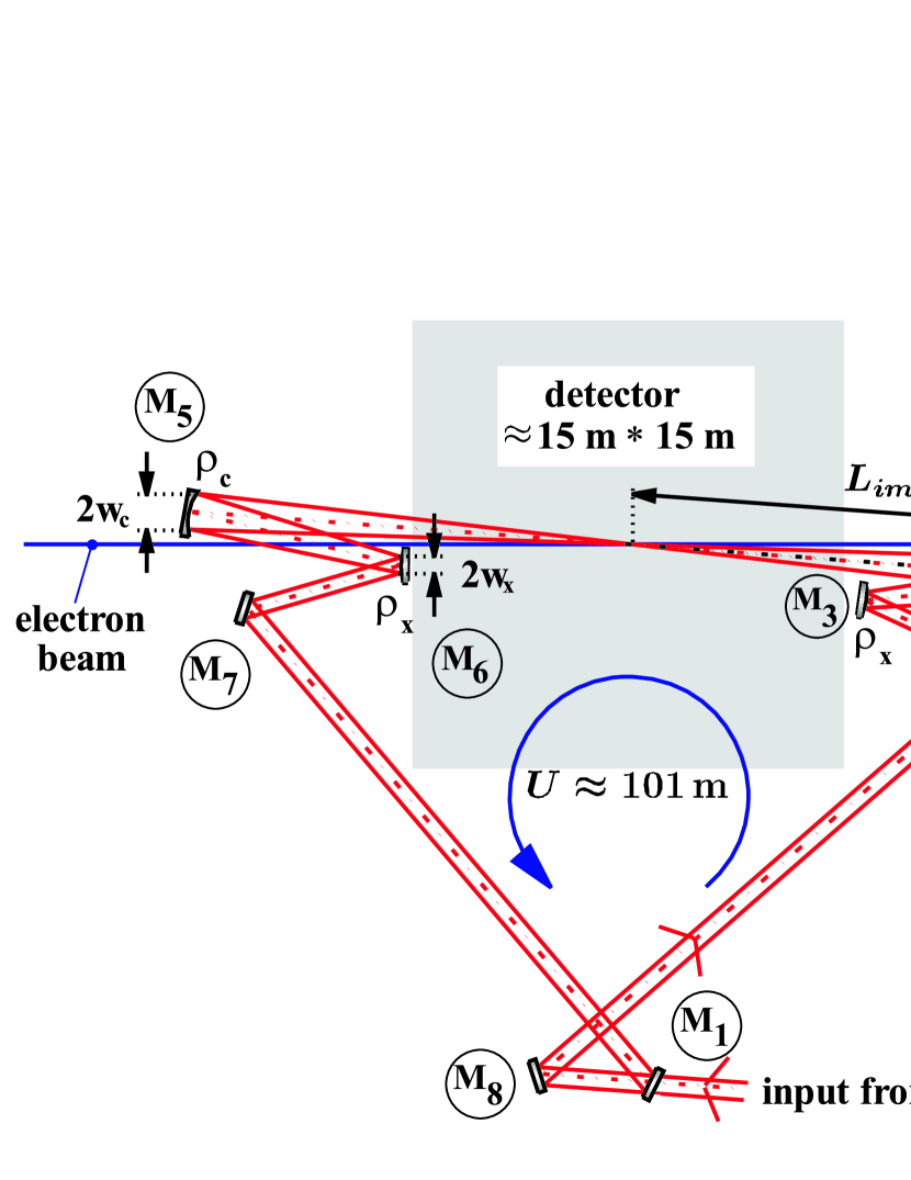
A telescopic convex-concave mirror arrangement generates a focus in the interaction region and a second, identical telescope re-collimates it again. In addition, they introduce a moderate beam magnification that reduces the beam size within the nearly collimated region of the cavity outside the detector. Here, the laser is coupled to the cavity via M1 or M8.
6 Telescopic cavity
Disregarding the final size of the mirrors the focal spot size at CP is determined by the Gaussian eigenmode within this cavity. That is calculated by setting up the round-trip matrix , [58]. We assume total correction of the aberrations of the telescope mirrors. When starting at a reference plane containing CP and proceeding in counter clockwise direction, one obtains for the proposed cavity the following dependence on the geometrical data:
| (25) |
| (26) |
This results from multiplication of 22-matrices describing the sequence of reflections on mirrors with radii of curvature and the free space propagations in between. represents the distance between both concave mirrors and . Between and the ring is closed by via , , and of Fig. 5 on the lower path. designates the length of the telescope (spacing between and as well as between , and ) and quantifies a detuning from the length for afocal alignment of the telescope set up by concave and convex mirrors of effective focal lengths and , respectively. Due to the inclined angle of incidence of the laser beam on the curved mirrors their focal lengths are modified, which is expressed by the effective value. They should have parabolic surfaces for reducing optical aberrations, predominantly astigmatism [59]. Suitable definitions for a design of the cavity are the beam magnification as the ratio of beam radii and on the concave and convex mirror of one telescope, as well as the final image distance between the focus and the concave mirror of each telescope when a collimated beam enters the telescope on the side of the convex mirror.
| (27) |
The location of the telescope within the cavity determines the beam size of the Gaussian focus at the reference plane CP [58]:
| (28) |
For a stable — i.e. on each revolution reproducing Gaussian beam — an additional confinement-condition has to be fulfilled:
| (29) |
The diameter of the final focusing concave mirrors determine the minimal collision angle between laser and electron beam. They should be kept small for high yield of . This however gives rise to an additional contribution to the total loss factor of the cavity due to diffractive power loss, to a diffraction broadening of the focal spot size and to deviations from the Gaussian mode. These were studied numerically using the physical optics code GLAD [60]. A Gaussian beam was injected into a cavity formed by perfect reflecting mirrors and was numerically propagated according the Fox-Li approach [61] throughout many revolutions, until a stationary field distribution was established. Then the beam size at the focus was calculated by the second moment of the electric field distribution. resulted from the fractional drop of power during one round-trip.
By reducing the size of the concave mirrors, the beam size on these mirrors also decreases, minimizing the optical power that is lost. This requires a growth of the beam waist at the CP. The relative broadening of the focal spot size compared to the Gaussian focal beam radius is plotted in Fig. 6
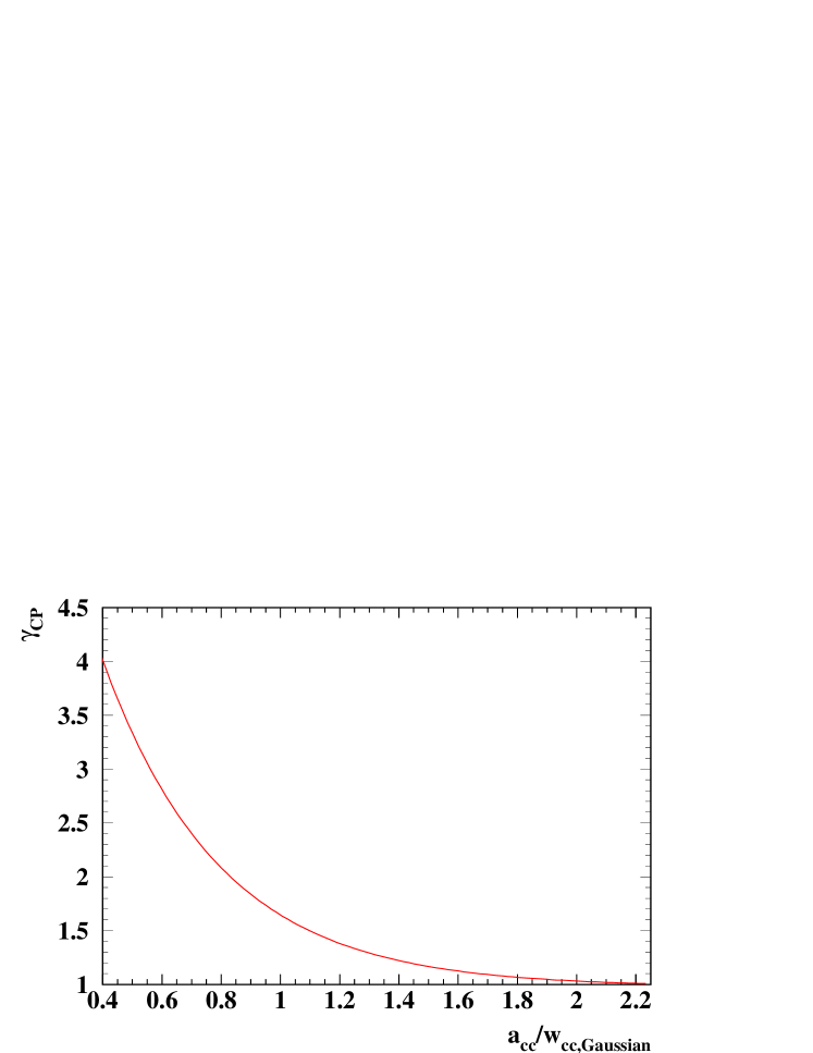
as a function of a normalized radius of the concave mirrors. It is expressed in units of the corresponding Gaussian beam radius at this location. This plot is characteristic for the layout of an optical cavity following Fig. 5 For reasons of self-resemblance the diffractive broadening behaves similar when the size of the focus within the cavity of Fig. 5 is varied by shifting both telescopes either an equal amount towards (reduction) or away (enlargement) from the CP.
As shown later the diffraction loss turns out to be negligible for parameters with acceptable .
7 Laser-electron crossing angle
In order to calculate the laser-electron crossing angle and to specify , diffraction broadening has to be taken into account. In respect to a high yield of , crossing angle , mirror diameter , waist size , laser pulse energy , as well as laser pulse duration are all interdependent parameters. Their respective values were determined by a numerical optimization process using the CAIN Monte Carlo code [62, 63, 64] which assumes charged particles interact with a Gaussian optical beam. The center-of-mass energy was set to 500 GeV. The aperture of the final focusing concave mirrors , at distance from the conversion point CP in Fig. (5) sets an upper limit for the opening angle of the laser cone that emerges from the beam waist:
| (30) |
Replacing by the far field divergence angle originating from a Gaussian beam waist results in the latter equation. represents the beam radius on each of the concave mirrors. For the TESLA parameters, an additional offset angle of 17 mrad occurs in view of the disruption of the electron beam during the Compton scattering and the physical size of the electron beam pipes near the interaction region. The crossing angle is thus expressed as
| (31) |
This relation was encoded into CAIN via the optical Rayleigh length by using the relation of Gaussian beams [65]. Instead of the Gaussian beam waist, the numerical value for the diffraction broadened waist = has been used for . Fig. 7 shows the resulting luminosity
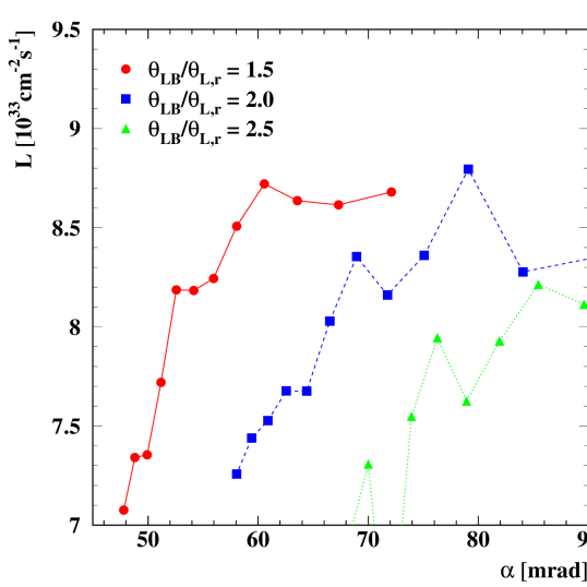
as a function of the crossing angle for different mirror sizes and a laser pulse duration of ps FWHM ( = 1.5 ps). In the examined range the luminosity rises with decreasing diameter of the mirrors. A value of is therefore selected. An acceptable crossing angle is then mrad. This corresponds to 0.63 mm, a diffraction broadened beam waist of 14.3 m () ( = 7.15 m) and a Gaussian waist 6.5 m () ( = 3.3 m)111() designates the radius that is defined by a drop of the intensity to 13.5 % of its maximum value at the beam center..
A total luminosity222Here is defined as consistent with the definition in [4]. of can be achieved for these parameters with a pulse energy of 9 J [66]. A non-linearity parameter can be maintained in accordance with reference [4]. In proportion to the laser pulse energy the required average laser power has also gone up to 9 J 2820 5 Hz 130 kW. All resulting parameters for the Compton interaction zone of a -collider based on 250 GeV electron beams are compiled in Tab. 1.
| laser pulse energy | 9.0 J |
| average laser power | 130 kW for one pass collisions at the |
| TESLA bunch-structure | |
| pulse duration | 3.53 ps FWHM ( = 1.5 ps) |
| Rayleigh length | 0.63 mm |
| beam waist | 14.3 m () ( = 7.15 m) |
| laser-e- crossing-angle | 56 mrad |
| normalized mirror-size | 0.75 |
| laser wavelength | 1.064 m |
| nonlinearity parameter | 0.30 |
| total luminosity | cm-2s-1 |
The diffraction broadened beam waist size of 14.3 m () corresponds to a Gaussian beam waist 6.5 m () ( = 3.3 m).
8 Specification and enhancement capability of the cavity
In view of the dimension of the particle detector, , , and were selected such that m. The design parameter of the optical cavity according to Fig. 5 are compiled in Tab. 2.
| = | 3041.85862 cm | = | 809.82 cm | = | 732.05 cm |
|---|---|---|---|---|---|
| = | 5597.05 cm | = | -1000.0 cm | = | 3.86 |
| L(M4, M3) = t | L(M7, M1) = L(M2, M8) |
| L(M3, M2) = 530 cm | L(M7, M6) = L(M3, M2) |
| L(M2, M8) = 2083.66 cm | L(M6, M5) = t |
| L(M8, M1) = 369.73 cm | L(M5, CP) = L(CP, M4) = |
| beam magnification | = |
| diameter of all mirrors | 120 cm |
The mode within the optical cavity produces its largest spot-size at the concave mirrors next to the beam waist. In a hypothetical cavity with mirrors of unlimited size a Gaussian beam of = 79.1 cm radius () would develop. Assuming a clipping aperture of 75 % of the Gaussian beam radius, i.e. = 0.75 = 59.3 cm 60 cm, the spot size on the concave mirrors reduces according to the numerical modelling to 42.7 cm. This leaves sufficient room for the wings of the electric field distribution as will be seen in the discussion of diffraction loss. The concave mirror should therefore have a diameter of about 120 cm. This yields a f-number = 12.7 for both focussing telescopes.
In this way the concave mirror is designed to represent the dominant aperture at which diffraction will occur. The telescope reduces the lateral extension of the mode by a factor of . However, a reduction of all other mirrors by this factor is not advisable without introducing further significant apertures. These would influence the beam size even further and create losses which in the end would reduce the efficiency of the Compton conversion. Therefore, all mirrors should have the same diameter of 120 cm.
A plot of the numerically obtained stationary diffraction loss factor as a function of the diffraction broadened beam waist is shown in Fig. 8.
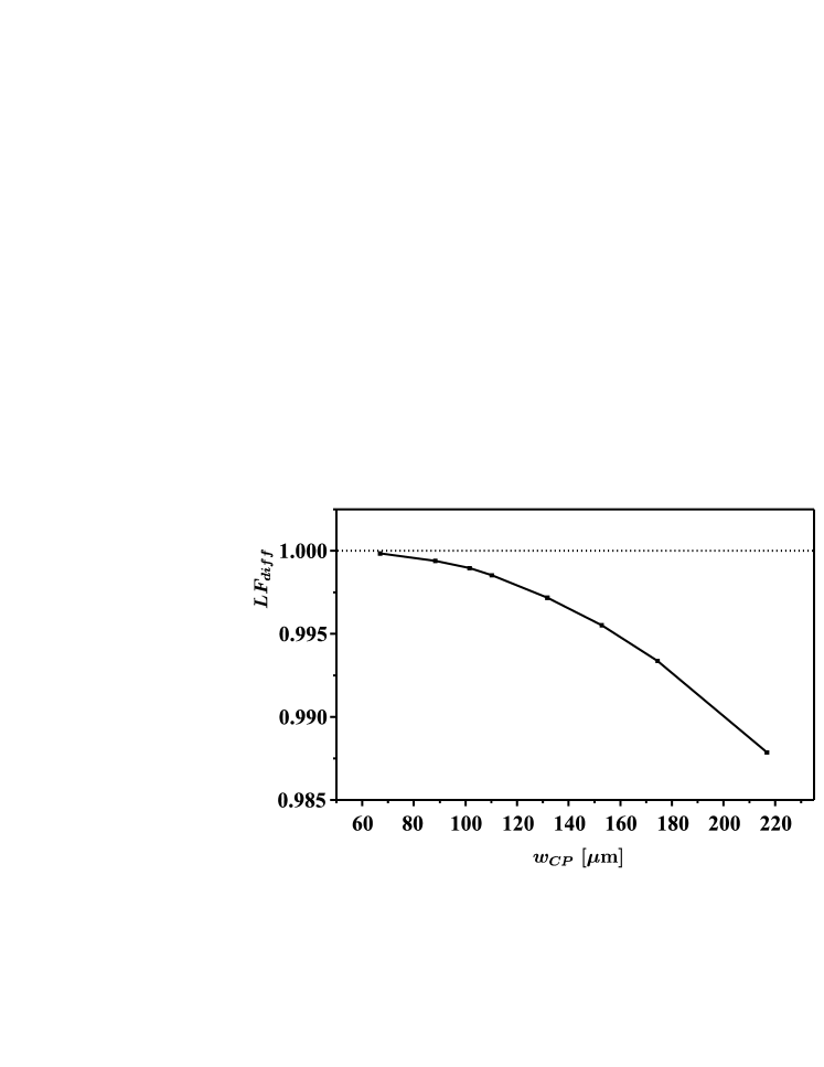
It results from slight variations of the distance between both telescopes. At the same time has been adjusted in the opposite direction, in order to keep the total path length unchanged. The diameter of all mirrors was thereby adapted to end up with the same ratio as for the optimized cavity. Diffraction loss declines according to Fig. 8 towards smaller foci within the cavity. = 1 denotes no power loss due to diffraction.
A diffraction loss factor of roughly was obtained from an extrapolation down towards m diffraction broadened beam waist. Taking the reflectivity of practical highly reflecting mirrors into account reduces the total loss factor to . denotes the reflectivity of all remaining mirrors with exception of the coupling mirror. A reflectivity between = 99.99 % and 99.95 % would permit a steady-state impedance matched power enhancement between 1100 and 270, for otherwise perfect conditions. The enhancement becomes the more sensitive against any impedance mismatch, the larger the amount of is. In practice, one probably will have a set of spare mirrors with slightly varying reflectivity and check which one will give the best enhancement.
Before onset of each electron bunch train additional laser pulses are required for the accumulation of a sufficient large optical pulse energy within the cavity, that will ensure an enhancement of at least the fraction () of the stationary amount . The number is derived from Eq. (16) as follows:
| (32) |
As an example, the build-up of power obtained from the numerical propagation of an optical pulse under Gaussian seed-conditions through many revolutions is represented by Fig. 9 for = 99 %, V = 0.9998, and = 100 %. At perfect resonance 1034 pre-pulses are then expected for obtaining an enhancement of at least 99 % of = 383, i.e. = 378.8. The stationary enhancement of 353 in Fig. 9 following in accordance with Eq. (32) after 1000 circulations of the pulse reflects a 92 % coupling of the injected Gaussian mode into the cavity mode. The number of laser pre-pulses for reaching an approximate steady-state declines as the impedance matching condition is violated.
When represents the power enhancement factor of the optical cavity, the required average power of the laser is reduced to , where is the number of electron bunches in one train.
9 Damage threshold
The TELSA bunch structure consists of bunch trains of 2820 bunches with about 300 ns bunch spacing and a train repetition rate of 5 Hz. This pulse structure represents an intermediate regime between two identified damage mechanisms [67]. For a pulse duration above 100 ps the damage occurs by melting due to heat deposition, whereas for less than 20 ps the damage site is limited to the region where the intensity is sufficient for a laser generated plasma. This occurs before a significant transfer of energy from the electrons to the lattice has taken place.
For 3.5 ps (FWHM) pulse duration the threshold for 600 shots at 10 Hz repetition rate and 1053 nm wavelength of uncoated very uniform fused silica samples is of the order of 2 J/cm2 [68], whereas just 5 mJ/cm2 per pulse results from the parameter for the cavity.
For a rough estimation of the worst case risk for material damage the cumulative effect of all pulses within the train is assumed to be represented by a single pulse with total energy and duration equivalent to that of all optical bunches within a train. The parameters of Tab. 1, 2 result then in a laser energy fluence of around 4 J/cm2 within 10 ns at the mirrors of the cavity for a hypothetical Gaussian beam and 13 J/cm2 for the cavity mode with truncated mirrors. At the final focussing concave mirrors this fluence is lower by a factor of 3 due to the beam expansion. According [67] the laser damage threshold for 10 ns pulse duration for various materials including fused silica and coatings is higher and lies around 50 J/cm2 for the substrat, and above approximately 44 J/cm2 to 120 J/cm2 for the mirrors depending on the composition of the multilayer coatings. Following the known scaling laws summarized e.g. in [67], for a wavelength around 1 m a further factor of for the increase of the threshold for the contribution due to thermal induced damage could probably be anticipated for distribution of the optical bunches within a train of 1 ms duration as in the TESLA time structure.
This means that the expected fluence is below the damage threshold. However, no data for trains of ps-pulses separated on nano- to microsecond time scales which accumulate to the stated fluences are known to us. For a final judgment an experimental study with a representative of the ILC bunch structure would be required.
10 Effects of cavity misalignments
¿From Eq. (18) the maximum acceptable length detuning for the circumference of the optical cavity for a tolerated fractional decline in the power enhancement factor from the resonance condition is derived to be given by
| (33) |
Maintaining the power enhancement factor e.g. above % of its optimum value demands a match of the circumference of the cavity of better 0.57 nm for an assumed value of 100. Technical solutions for such a precise length stabilization are well-known [69]. Even more stringent restrictions are common in interferometrical detection of gravitational waves.
Any misalignment generally results in displacement and broadening of the intra-cavity beam waist. Mechanical vibrations due to instrumentation in the environment of the particle detector, seismic ground motion as well as slight deviations during assembly might slightly modify position and tilt of the mirrors. According to our calculations, the displacement of the beam waist remains smaller then the Rayleigh length, i.e. the depth of the focus. This shift of the beam waist is hence negligible.
Broadening of the waist modifies the cavity-mode and reduces the mode coupling between laser and cavity. The resulting relative decline of the power enhancement factor was found to be largely independent of the finesse of the cavity. As an example two identical cavities with enhancement factors of 353 and 76, respectively, were considered. Fig. 10 shows the effect of shifting one telescope
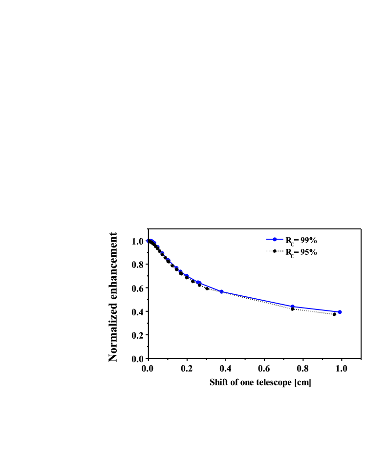
over a range of up to 1 cm from its designated location away from the waist. Its internal alignment was assumed as being preserved. Regarding this vast variation range compared to the Rayleigh length in Tab. 2, the decline for sub-mm shifts is rather modest. It remains below 20 %. At a shift of 1 cm reduces the enhancement to 40 % of . A decline of similar amount occurs e.g. for a deviation of the focal length of the convex mirror of 12 mm.
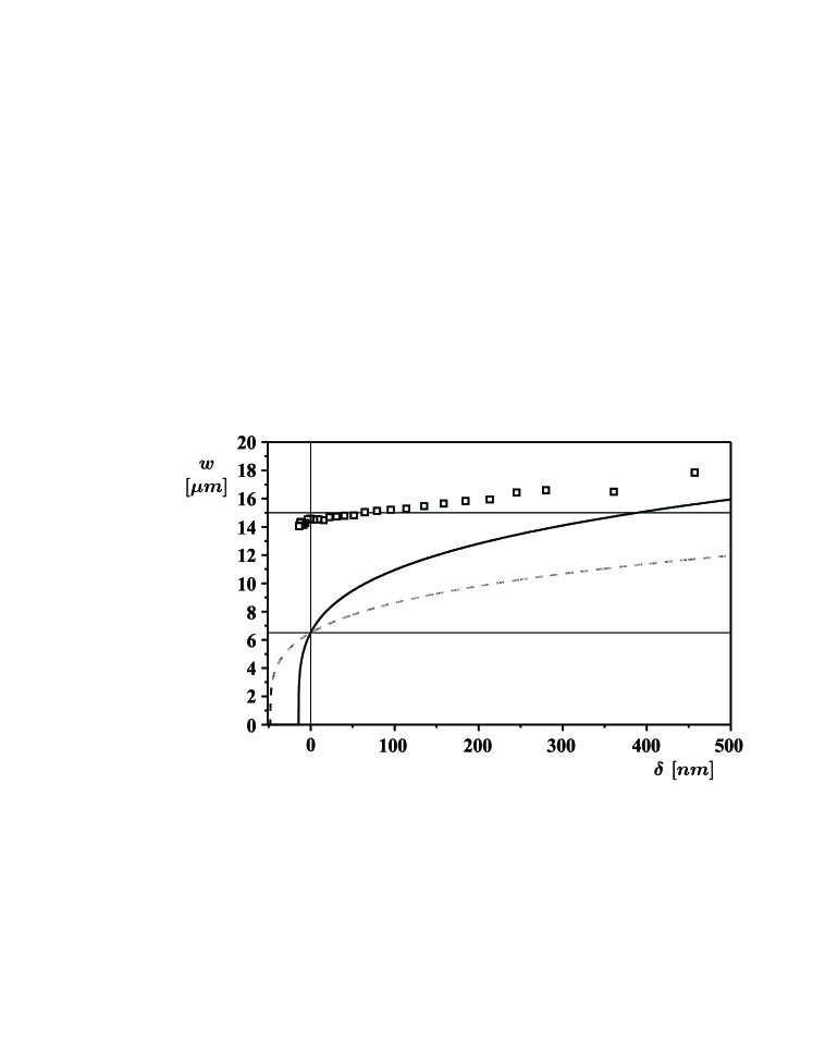
An increase of the focal length or shift of the telescope away from CP (the location of the beam waist) is accompanied by an increase of the radius of the beam waist. The latter is depicted by Fig. 11. Under the influence of clipping at the concave mirrors the growth of the diffraction broadened beam size is considerably lower. This allows to shift the operating point of the cavity further away from the stability limit. A zero waist size denotes an instable optical cavity.
11 Discussion
The -collider will be operated with trains of optical ps-pulses, whereas the optical interferometric detection of gravitational waves relies on continous-wave (cw) laser radiation. An automatic alignment system has already been developed for gravitational wave detection [70, 71]. Therefore, use of an additional uninterrupted train of weak ps-pulses for generation of error signals resulting from misaligned components and constant control of the cavity seems promising, as the cavity for the -collider can benefit from that knowledge.
The tiny absorption of the laser beam within the substrate and mirror coating is expected to induce a nonuniform temperature increase within the optic due to the amount of circulating optical power. This causes a nonuniform distortion of the optical path length by thermal expansion of the optic’s surface, and a variation of the material’s refractive index with temperature (thermal lensing). In our numerical model the focal length has to stay within a few tenth mm of its exact value for missing the desired beam waist by not more than 5 %. A correction of the curvature radius of imaging mirrors has already been demonstrated by exerting an axially symmetrical mechanical strain within the reflecting surface through radiative heating [72]. The remaining non-axial-symmetric wavefront distortion generated by inhomogeneities in the substrate can be compensated by locally heating the mirror in addition with another laser via further computer controlled scanning mirrors. A proof-of-principle experiment has been performed in [73].
Moreover, the high misalignment sensitivity of the proposed cavity could be overcome by the introduction of adaptive optics for ensuring and controlling the development of a diffraction limited optical mode. This requires an additional control loop acting on the surface shape of at least one deformable mirror. The flat folding mirrors M1 and M2 adjacent to the telescopes in Fig. 5 appear to be especially well suited for this task.
The proposed cavity approximates a half-degenerate cavity which is characterized by a round-trip matrix of -1 times the unity matrix. In a half-degenerate cavity, the intensity distribution at any position along the propagation axis is relay imaged at completion of two circulations. Such a cavity can already be described in good approximation by ray-tracing (geometric-optical imaging). Diffraction has only be taken into account for calculation of the focus.
12 Conclusion
The actual enhancement factor of the cavity results from the cumulative effect of many small contributions affecting the total loss factor. Residual abberations tend to enlarge the focused beam at the Compton conversion point. Both are difficult to predict in advance. However, the influence of diffraction loss is for the proposed cavity almost negligible.
According to an estimation based on the known properties of laser induced damage, the suggested size of the mirrors provides still some reserve before the energy fluence of the circulating optical pulse reaches the damage threshold. For a final judgement of the upper limit, an experimental study with a representative of the special ILC bunch structure is required.
The use of adaptive optics appears to be essential for operation of such a cavity.
13 Acknowledgements
We would like to thank J. Gronberg, I.N. Ross, A. Stahl, and V. Telnov for many useful discussions. We are also grateful to F. Bechtel for his help during numerical calculations of the luminosity optimization as well as to N. Meyners of DESY’s MEA department for preparing the steric schemes used in Fig. 4.
References
- [1] http://sbhep1.physics.sunysb.edu/grannis/lc_consensus.html.
-
[2]
International Committee for Future Accelerators (ITRP):
http://www.ligo.caltech.edu/skammer/ITRP_Home.htm,
ITRP Final Report September 2004:
http://www.ligo.caltech.edu/%7Eskammer/ITRP/ITRP_Report_Final2.pdf - [3] R. Brinkmann et al., TESLA: The superconducting electron positron linear collider with an integrated X-ray laser laboratory. Technical design report. Part II: The accelerator, DESY-01-011B.
- [4] B. Badelik et al. “The photon collider at TESLA,” Int. J. Mod. Phys. A 19(30), 5097–5186 (2004).
- [5] I. F. Ginzburg, G. L. Kotkin, V. G. Serbo, and V. I. Telnov, “Production of high-energy colliding and beams with a high luminosity at vlepp accelerators,” JETP Lett., 34, 491–495 (1981).
- [6] I. F. Ginzburg, G. L. Kotkin, V. G. Serbo, and V. I. Telnov, “Colliding and beams based on the single-pass colliders (VLEPP type),” Nucl. Instrum. Methods 205, 47–68 (1983).
- [7] I. F. Ginzburg, G. L. Kotkin, S. L. Panfil, V. G. Serbo, and V. I. Telnov, “Colliding and beams based on the single pass accelerators. 2. polarization effects. monochromatization improvement,” Nucl. Instrum. Meth. A 219, 5–24 (1984).
- [8] V. Telnov, “Principles of photon colliders,” Nucl. Instrum. Meth. A 355, 3–18 (1995).
- [9] S. Schreiber, I. Will, D. Sertore, A. Liero, and W. Sandner, “Running experience with the laser system for the RF gun based injector at the TESLA Test Facility linac,” Nucl. Instrum. Meth. A 445, 427–431 (2000).
- [10] I. Will, G. Koss, and I. Templin, “The upgraded photocathode laser of the TESLA Test Facility,” Nucl. Instrum. Meth. A 541, 467–477 (2005).
- [11] D. D. Meyerhofer, “High intensity lasers for gamma-gamma colliders,” Nucl. Instrum. Meth. A 355, 113–120 (1995).
- [12] C. E. Clayton, N. A. Kurnit and D. D. Meyerhofer, “Application of conventional laser technology to gamma-gamma colliders,” Nucl. Instrum. Meth. A 355, 121–129 (1995).
- [13] V. Telnov, “Status of gamma-gamma and gamma-electron colliders,” Nucl. Phys. B-Proc. Suppl. 82, 359–366 (2000).
- [14] V. Telnov, “Photon colliders: key problems, new ideas” Int. J. Mod. Phys. A 15, 2577–2586 (2000).
- [15] I. Will, T. Quast, H. Redlin, and W. Sandner, “A laser system for the TESLA photon collider based on an external ring resonator,” Nucl. Instrum. Meth. A 472, 79–85 (2001).
- [16] F. Torabi-Goudarzi and E. Riis, “Efficient cw high-power frequency doubling in periodically poled KTP,” Opt. Commun. 227, 389–403 (2003).
- [17] H. Kumagai, Y. Asakawa, T. Iwane, K. Midorikawa, and M. Obara, “Efficient frequency doubling of 1-W continuous-wave Ti:sapphire laser with a robust high-finesse external cavity,” Appl. Opt. 42(6), 1036–1039 (2003).
- [18] T. Freegarde and C. Zimmermann, “On the design of enhancement cavities for second harmonic generation,” Opt. Commun. 199, 435–446 (2001).
- [19] A. Ashkin, G. Boyd, and J. Dziedzic, “Resonant optical second harmonic generation and mixing,” IEEE J. Quantum Electron. QE-2, 109–124 (1966).
- [20] G. McConnell, A. I. Ferguson, and N. Langford, “Cavity-augmented frequency tripling of a continuous wave mode-locked laser,” J. Phys. D Appl. Phys. 34, 2408–2413 (2001), Online at stacks.iop.org/JPhysD/34/2408.
- [21] M. A. Persaud, J. M. Tolchard, and A. Ferguson, “Efficient Generation of Picosecond Pulses at 243 nm,” IEEE J. Quantum Electron. QE-26(7), 1253–1258 (1990).
- [22] G. Maker and A. Ferguson, “Efficient frequency doubling of a mode-locked diode-laser-pumped Nd:YAG laser,” Appl. Phys. Lett. 55, 1158–1160 (1989).
- [23] R. Schumann, M. Dammasch, U. Eichmann, Y. Kriescher, G. Ritter, G. von Oppen, “Laser spectroscopy on the Stark effect of the level of He i,” J. Phys. B - At. Mol. Opt. 30, 2581–2590 (1997).
- [24] M. Dammasch, “Laserkühlung von metastabilem Helium in elektrischen Feldern,” Diploma Thesis, TU-Berlin, Max-Born-Institut Berlin (1996).
- [25] Ma Long-Sheng and J. L .Hall, “Optical Heterodyne Spectroscopy Enhanced by an External Optical Cavity: Toward Improved Working Standards,” IEEE J. Quantum Electron. QE-26(11), 2006–2012 (1990).
- [26] J. C. Garreau, M. Allegrini, L. Julien, and F. Biraben, “High resolution spectroscopy of the hydrogen atom. I. Method and experiment,” J. Phys. (Paris) 51, 2263–2273 (1990).
- [27] M. G. Boshier, P. E. G. Baird, C. J. Foot, E. A. Hinds, M. D. Plimmer, D. N. Stacey, J. B. Swan, D. A. Tate, D. M. Warrington, and G. K. Woodgate, “Laser spectroscopy of the 1S-2S transition in hydrogen and deuterium: Determination of the 1S Lamb shift and the Rydberg constant,” Phys. Rev. A 40, 6169–6184 (1989).
- [28] E. Inbar and A. Arie, “High sensitivity CW Fabry-Perot enhanced spectroscopy of CO2 and C2H2 using a 1064-nm Nd:YAG laser,” Appl. Phys. B 68, 99–105 (1999).
- [29] R. Engeln, G. Berden, R. Peeters, and G. Meijer, “Cavity enhanced absorption and cavity enhanced magnetic rotation spectroscopy,” Rev. Sci. Instrum. 69, 3763–3769 (1998).
- [30] D. Romanini, A. A. Kachanov, N. Sadeghi, and F. Stoeckl, “CW-cavity ring down spectroscopy,” Chem. Phys. Lett. 264, 316–322 (1997).
- [31] K. Nakagawa, T. Katsuda, A. Shelkovnikov, M. de Labachelerie, and M. Ohtsu, “Highly sensitive detection of molecular absorption using a high finesse optical cavity,” Opt. Commun. 107, 369–372 (1994).
- [32] T. German and D. Romanini, “Mode-locked cavity enhanced absorption spectroscopy,” Opt. Express 10, 1033-1042 (2002).
- [33] E. R. Crosson, P. Haar, G. A. Marcus, H. A. Schwettman, B. A. Paldus, T. G. Spence, and R. N. Zare, “Pulse-Stacked cavity ring-down spectroscopy,” Rev. Sci. Instrum. 70, 4–10 (1999).
- [34] T. Smith, P. Haar, and H. Schwettmann, “Pulse stacking in the SCA/FEL external cavity,” Nucl. Instrum. Meth. A 393, 245–251 (1997).
- [35] Z. Vidne, M. Rosenbluth, and T. W. Hänsch, “Pulse picking by phase-coherent additive pulse generation in an external cavity,” Opt. Lett. 28(23), 2396–2398 (2003).
- [36] E. O. Potma, C. E. Evans, X. S. Xie, R. J. Jones, and J. Ye, “Picosecond-pulse amplification with an external passive optical cavity,” Opt. Lett. 28(19), 1835–1837 (2003).
- [37] R. Jones and J. Ye, “Femtosecond pulse amplification by coherent addition in a passive optical cavity,” Opt. Lett. 27(20), 1848–1850 (2002).
- [38] H. Lück, and the GEO600 Team “The GEO600 project,” Classical Quant. Grav. 14, 1471–1476 (1997).
- [39] K. A. Strain, private communication, Department of Physics and Astronomy, University of Glasgow (2006).
- [40] H. Sakai et al, “Measurement of a small vertical emittance with a laser wire beam profile monitor,” Phys. Rev. ST Accel. Beams 5, 122801 (2002).
- [41] H. Sakai et al., “Performance studies of a laser wire beam profile monitor,” Jpn. J. Appl. Phys. 1 41(11A), 6398–6408 (2002).
- [42] H. Sakai, Y. Honda, N. Sasao, S. Araki, Y. Higashi, T. Okugi, T. Taniguchi, J. Urakawa, and M. Takano, “Performance studies of a laser wire beam profile monitor,” Jpn. J. Appl. Phys. 11A, 6398–6408 (2002).
- [43] H. Sakai et al. “Measurement Of An Electron Beam Size With A Laser Wire Beam Profile Monitor,” Phys. Rev. ST Accel. Beams 4, 022801 (2001).
- [44] H. Sakai et al, “Development Of A Laser Wire Beam Profile Monitor (2),” Nucl. Instrum. Meth. A 455, 113–117 (2000).
- [45] T. Shintake, “Proposal of Nanometer beam size monitor for e+ e- linear colliders,” Nucl. Instrum. Meth. A 311, 453–464 (1992).
- [46] M. Beckmann et al, “The longitudinal polarimeter at HERA,” Nucl. Instrum. Meth. A 479, 334–348 (2002).
- [47] I. Passchier, C. W. de Jager, N. H. Papadakis, N. P. Vodinas, D. W. Higinbotham, and B. E. Norum, “A Compton Backscattering Polarimeter For Measuring Longitudinal Electron Polarization,” Nucl. Instrum. Meth. A 414, 446–458 (1998).
- [48] http://sldb1.slac.stanford.edu/sldwww/polarimetry/content.html.
- [49] K. Kim and A. M. Sessler, “Photon storage cavities,” Nucl. Instrum. Meth. A 318, 895–898 (1992).
- [50] T. Mohamed, G. Andler, and R. Schuch “Development of an electro-optical device for storage of high power laser pulses,” Opt. Commun. 214, 291–295 (2002).
- [51] T. Mohamed, G. Andler, and R. Schuch “Active optical storage ring for high-power laser pulses,” Appl. Phys. B 79, 817–821 (2004).
- [52] A. Papoulis, Systems and Transforms with Applications in Optics (McGraw-Hill, 1968).
- [53] G. Cesini, G. Guattari, and G. Lucarini, C. Palma,“Response of Fabry-Perot interferometers to amplitude-modulated light beams,” Optica Acta 24(12), 1217–1236 (1977).
- [54] M. Born, E. Wolf, Principles of Optics (Cambridge University Press, 1999).
- [55] A. E. Siegman, Lasers (University Science Books, Mill Valley, Calif., 1986), Chapter 10.2.
- [56] W. Koechner, Solid-State Laser Engineering (Springer Series in Optical Sciences, Vol.1, 1999), Chapter 4, 11
- [57] N. Meyners and K. Sinram “Mechanical concept of the TESLA detector,” LC-DET-2001-045.
- [58] A. E. Siegman, Lasers (University Science Books, Mill Valley, Calif., 1986), Chapter 21.
- [59] D. Korsch, Reflective Optics (Academic Press, Inc., 1991).
- [60] G. N. Lawrence, General Laser Analysis and Design code (GLAD), released by Applied Optics Research, http://www.aor.com, 1986-2001.
- [61] A. Fox and T. Li, “Resonant modes in a maser interferometer,” Bell Syst. Techn. J. 40, 453–425 (1961).
- [62] K. Yokoya, “A computer simulation code for the beam-beam interaction in linear colliders,” KEK-Report-85-9 (1985).
- [63] K. Yokoya, “CAIN,”: A computer simulation code for the interaction of electron, positron, gamma beams and strong lasers. Available at http://www-acc-theory.kek.jp/members/cain/.
- [64] P. Chen, T. Ohgaki, A. Spitkovsky, T. Takahashi, and K. Yokoya, “Simulations of the interaction region in a photon-photon collider,” Nucl. Instrum. Meth. A 397, 458–464 (1997).
- [65] A. E. Siegman, Lasers (University Science Books, Mill Valley, Calif., 1986), Chapter 18.
- [66] F. Bechtel, http://www-zeuthen.desy.de/ILC/gammagamma/lumi_opt.ps.gz.
- [67] W. Koechner, Solid-State Laser Engineering (Springer Series in Optical Sciences, Vol.1, 1999), Chapter 11.
- [68] B.C. Stuart, M.D. Feit, S. Herman, A.M. Rubenchik, B.W. Shore, and M.D. Perry, “Nanosecond-to-femtosecond laser-induced breakdown in dielectrics,” Phys. Rev. B 53, 1749–1761 (1996).
- [69] R. Drever, J. Hall, F. Kowalski, J. Hough, G. Ford, A. Munlez, and H. Ward, “Laser Phase and Frequency Stabilization Using an Optical Resonator,” Appl. Phys. B31, 97–105 (1983).
- [70] R. Lawrence, M. Zucker, P. Fritschel, P. Marfuta, and D. Shoemaker, H. Grote, G. Heinzel, A. Freise, S. Gossler, B. Willke, H. Lück, H. Ward, M. Casey, KA. Strain, D. Robertson, J. Hough, and K. Danzmann, “The Automatic Alignment System of GEO 600,” Classical Quant. Grav. 19, 1849–1855 (2002).
- [71] G. Heinzel, A. Rüdiger, R. Schilling, K. Strain, W. Winkler, J. Mizuno, and K. Danzmann, “Automatic beam alignment in the Garching 30-m prototype of a laser-interferometric gravitational wave detector,” Opt. Commun. 160, 321–334 (2001), and Opt. Commun. 164, 161 (2001) (Corrigendum).
- [72] R. Lawrence, M. Zucker, P. Fritschel, P. Marfuta, and D. Shoemaker, “Adaptive Thermal Compensation of Test Masses in Advanced LIGO,” Classical Quant. Grav. 19, 1803–1812 (2002).
- [73] H. Lück, K.O. Müller, P. Aufmuth, and K. Danzmann, “Correction of Wavefront Distortions by Means of Thermally Adaptive Optics,” Opt. Commun. 175, 275–287 (2000).