Using Electrons on Liquid Helium for Quantum Computing
Abstract
We describe a quantum computer based on electrons supported by a helium film and localized laterally by small electrodes just under the helium surface. Each qubit is made of combinations of the ground and first excited state of an electron trapped in the image potential well at the surface. Mechanisms for preparing the initial state of the qubit, operations with the qubits, and a proposed readout are described. This system is, in principle, capable of operations in a decoherence time.
PACS numbers: 03.67.Lx, 73.20.-r.
I INTRODUCTION
A full description of quantum computing is beyond the scope of this paper. More complete descriptions are given elsewhere.[1]
A classical computer has binary bits with values that are either or . A quantum computer is operated with quantum bits, called qubits. Each qubit uses two energy levels of a quantum system for the components and . However, a qubit can be in a state that is a superposition of these two components,
| (1) |
A quantum computer would use a superposition of many qubit states. An n-qubit system has basis vectors, , which can be taken as products of the basis vectors of each of the qubits. An arbitrary combination of these can be written as
| (2) |
An example of a basis vector for the five qubit case (for ) is, = .
The superposition states represented by Eqs. (1) and (2) are responsible for the great potential advantage of quantum logic operations relative to classical ones. In the classical case an operation starts, proceeds and ends with every qubit in a given state. In the quantum case, an operation can use qubits in a superposition of many possible basis states. Operation on such superposition states can be equivalent to performing a large number of computations in parallel. The difficulty in utilizing this advantage arises from the fundamental nature of measurement in quantum processes, namely that measurement of the energy of an individual qubit will necessarily collapse the wave function so that the result can be only either or for each qubit. This requires algorithms that can yield definite answers to computations even though the square of the coefficients represent only probabilities.
For quantum logic operations with a physical system one must have
a) discrete states that can be identified with the components or .
b) a method to prepare an initial state.
c) a method for operating quantum gates.
d) a readout mechanism.
e) a coherence time sufficient to undertake a large number of operations.
f) for practical computing the system must be scalable to a large number of qubits.
We describe here a proposed quantum computer with qubits made of electrons on the surface of a liquid helium film and describe our method for fabricating the qubits and the methods by which their quantum states can be manipulated and measured. This system was first proposed by Platzman and Dykman[2] and has been described elsewhere.[3, 4, 5, 6]
II ELECTRONS ON HELIUM
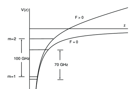
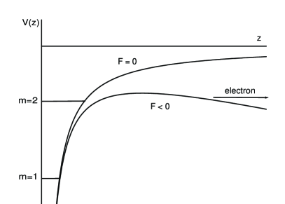
Electrons are bound to the surface of liquid helium by the dielectric image potential. A repulsive Pauli potential prevents them from penetrating into liquid helium. The hydrogenic-like potential is of the form
| (3) |
where is the coordinate normal to the surface, and is the dielectric constant of helium. The energy levels form a Rydberg spectrum, . We give parameters for liquid 3He; = , = meV, and the Bohr radius for this problem is = nm. The average separation of the electron from the surface is = nm and nm for the ground and first excited state, respectively. The transition frequency between the ground and first excited state[7] is GHz. These transitions can be shifted with a Stark field[8] applied normal to the surface. The potentials with and without a Stark field are shown in Fig. 1.
III DESIGN OF THE COMPUTER
We identify the ground and first excited states of these electrons with the states and , respectively. In order to address and control the qubits each electron must be localized laterally. This will be accomplished by locating electrons above microelectrodes (posts) that are separated by about m. The electrons will be separated from the tops of the posts by a m thick helium film. The lateral confinement results from the image potentials of the posts and the electric field from the potential on the posts, and the electron will be in the ground state for lateral motion at low temperatures.
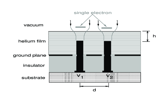
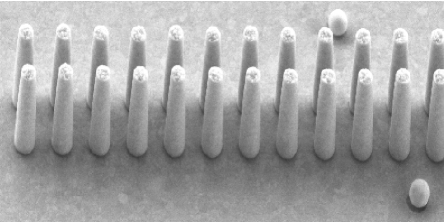
A schematic of posts and electrons for a two-qubit system is shown in Fig. 2. A voltage applied to a given post controls the Stark field for the corresponding electron. An array of posts fabricated at the Cornell Nanofabrication Facility is shown in Fig. 3. A prototype with lead wires to the posts and an isolated ground plane to screen the field from the leads has also been fabricated. Numerical computations of the electric field from the posts and ground plane have been completed and fabrication of a final design is in progress. Note that this system is scalable to an arbitrary number of posts or qubits.
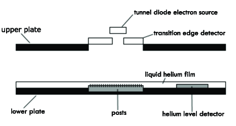
A schematic of our cell is shown in Fig. 4. The posts will be located in the bottom of a waveguide that transmits sub-mm radiation to the electrons. Superconducting microbolometers will be located at the top of the guide to detect electrons that are allowed to escape from the posts. A tunnel-diode electron-emission source will be located above the electron detectors. Electrons will be loaded onto the film through a hole in the detector chip, and one electron will be trapped over each post by an applied positive potential. The thickness of the helium film will be measured with a capacitor made of metal strips deposited on a part of the ground plane containing the posts that extends outside of the waveguide. The electrodes of the capacitor are in the shape of a comb with interwoven teeth spaced by approximately one micron. The system will be operated at mK to increase coherence times of the qubit states.
Our initial tests will be on a 3He film. The microwave setup for 3He is easier to work with because the transition frequencies are lower and the corresponding waveguide is larger. There a number of other advantages in using 3He. Liquid 3He has a large viscosity at low temperatures. This should severely dampen high-frequency ripplons involved in T1 and T2 processes, although new decoherence processes involving interactions with the bulk 3He may occur. Thermal contact between the sample chamber and 3He is much easier to achieve than for 4He, and the surface is less affected by microphonics. Finally, the larger separation of the electrons from the surface leads to a somewhat larger dipole interaction between neighboring states.
IV OPERATIONS
The operation would normally begin with all qubits in the ground state. Then according to the requirements of the desired operations, each qubit would be prepared in some admixture of states and by Stark shifting individual qubits into resonance with microwave radiation for a predetermined time.[3, 5] The state of the qubit will be
| (4) |
where , is the Rabi frequency, is the strength of the rf field, and is the time the qubit is in resonance with the microwave field.
In general, computations will be implemented by applying pulses of radiation to interacting qubits. We illustrate a potential operating mode of the system by describing two qubits operated as a swap gate. The interaction between qubits is via the Coulomb energy, which is much larger than the interaction between the induced dipole moment of each qubit. The dipolar component of the direct interaction potential between qubits and is
| (5) |
where is the electron separation, and is the separation of the electron from the helium surface. Start with one qubit in the state and the other in the state . Next apply the same Stark fields to both qubits so that the states and would be degenerate. In this condition the system will oscillate between the two states at a frequency given by the interaction energy, which in first order is given by . This frequency is GHz for a separation of m. By leaving the electric fields in this condition for one half cycle of this oscillation, the two qubits will swap states. It will be difficult to tune neighboring qubits to precisely identical Stark shifts, and in practice we may sweep the Stark shift of one qubit through resonance with a neighboring qubit.[5] In this case, the final state of the qubit will depend on the rate at which the electric field is swept through the resonance condition.
Readout. The wavefunction of the system of entangled qubits collapses when a measurement is made. Thus, the states of all qubits must be read within the time scale is set by the plasma frequency GHz. We describe here our initial proposal for a destructive readout pending research into other schemes. We will apply a short, ns, ramp of an extracting electric field to all qubits. The potential for a fixed value of extracting field is shown in Fig. 5. The tunneling probability is exponential in the time-dependent barrier height. All electrons in the upper state will tunnel through the barrier within a short period of time when this probability becomes sufficiently large. The escape of an electron will be detected by the bolometer detector mentioned above. For this extracting field the tunneling probability will be negligibly small for electrons in the ground state. After the ramp is removed the remaining electrons will be in the ground state. Subsequently, we plan to sequentially apply to each post an extracting field sufficiently large so that electrons in the ground state will tunnel from the surface.[9] A will be registered for each electron detected and a for those states that are empty.
An alternate scheme would be to apply an extracting voltage to the post under one electron at a time. For small numbers of qubits in our initial exploratory experiments, the system would then be prepared in the same state repeatedly and a different qubit sampled each time the operation is carried out. Ultimately we hope to develop a non-destructive readout that will allow simultaneous measurement of the states of all qubits without allowing the electrons to escape.
V DECOHERENCE
All logic operations must be accomplished in less time than it takes for the interactions of the qubit with the environment to destroy the phase coherence of the state functions. For electrons on 4He the lifetime of the excited state is limited by interactions with ripplons. The electron-ripplon coupling Hamiltonian[2, 3, 5] is
| (6) |
where is the normal component of the electric field that includes both the applied field and variations in the helium dielectric image field due to surface distortions, and is the amplitude of the surface height variation. The average rms thermal fluctuation of the surface is
| (7) |
The transition from the excited to ground state requires a ripplon with a wave vector . For a single electron on bulk helium a radiationless transition occurs with the energy absorbed by electron plane-wave states for motion parallel to the surface and momentum absorbed by ripplons. For this case a calculation of T1 yields
| (8) |
where is the transition frequency. At T mK, , and T1 s.
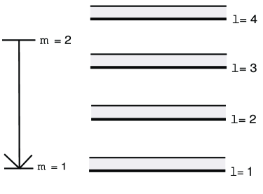
For electrons confined by posts, the lateral states are harmonic oscillator states of the image potential well of the posts. These are separated in energy[10] by mK. For an array of electrons there is a band of plasma oscillations associated with each harmonic oscillator level, which for an electron separation of m on bulk helium has a band width that is greater than mK. The confining potential of the posts reduces the width of this band. Preliminary calculations[10] suggest that the width may be sufficiently small to prevent conservation of energy in a radiationless transition. This is illustrated in Fig. 6 where the transition is shown to be incommensurate in energy with an excitation between the harmonic oscillator states. Suppression of this relaxation channel would lead to a very large value of T1.
If the confining potential does not sufficiently reduce the width of the plasma band, this will be accomplished with an applied magnetic field. A magnetic field confines the lateral states to Landau levels with a band of plasma oscillations of width . Here and are, respectively, the zone-boundary plasmon of the ordered qubit array and cyclotron frequencies. The transitions between Landau levels with the emission of one ripplon cannot conserve energy and momentum for Tesla.
The two-ripplon process can either cause a transition to the ground state or lead to dephasing by an incoherent phase modulation due to quasi-elastic scattering within a ”hydrogenic level” by thermal ripplons with a wave vector equal to the inverse cyclotron radius[11]. At mK and a field of Tesla, this leads to a dephasing time[10] T2 of ms. Single operations can be made in ns. Thus, in principle, operations can be preformed in a decoherence time.
High frequency ripplons are strongly damped on a liquid 3He surface. Thus, it is possible that the values of T1 and T2 may be longer than for 4He. A possible dephasing mechanism for the case of 3He is via interactions of the electron with excitations on the Fermi surface of bulk 3He. Theoretical calculations of this mechanism have not been carried out.
ACKNOWLEDGMENTS
The authors wish to acknowledge Mark Dykman for helpful conversations. This work was supported in part by NSF grant EIS-0085922.
REFERENCES
- [1] See for example, M.A. Nielsen and I.L. Chuang, Quantum Computation and Quantum Information (Cambridge University Press, Cambridge, 2000), or H-K. Lo, S. Popescu, and T. Spiller, Introduction to Quantum Computation and Information (World Scientific, Singapore, 1998).
- [2] P.M. Platzman and M.I. Dykman, Science 284, 1967 (1999).
- [3] M.I. Dykman and P.M. Platzman, Fortschr. Phy. 48, 1095 (2000).
- [4] M.J. Lea, P.G. Frayne, and Yu. Mukharshy, Fortschr. Phy. 48, 1109 (2000).
- [5] M.I. Dykman and P.M. Platzman, Quantum Information and Computation 1, to be published.
- [6] J.M. Goodkind and S. Pilla, Quantum Information and Computation 1, to be published.
- [7] A.P. Volodin and V.S. Edel’man, Zh. Eksp. Teor. Fiz. 81, 368 (1981);JETP 54, 198 (1981).
- [8] C.C. Grimes and G.A. Adams, Phys. Rev. Lett. 42, 795 (1979).
- [9] G.F. Saville and J.M. Goodkind, Phys. Rev. A. 50, 2059 (1994).
- [10] M.I. Dykman and P.M. Platzman, to be published.
- [11] M.I. Dykman, Phys. Status Solidi B 88, 463 (1978).