Reversible addition circuit using one ancillary bit with application to quantum computing
Abstract
Most of the work on implementing arithmetic on a quantum computer has borrowed from results in classical reversible computing (e.g. [VBE95], [BBF02],[DKR+04]). These quantum networks are inherently classical, as they can be implemented with only the Toffoli gate. Draper [D00] proposed an inherently “quantum” network for addition based on the quantum Fourier transform. His approach has the advantage that it requires no carry qubits (the previous approaches required carry qubits). The network in [D00] uses quantum rotation gates, which must either be implemented with exponential precision, or else be approximated. In this paper I give a network of Toffoli gates for reversibly performing in-place addition with only a single ancillary bit, demonstrating that inherently quantum techniques are not required to achieve this goal (provided we are willing to sacrifice quadratic circuit depth). After posting the original version of this note it was pointed out to me by C. Zalka that essentially the same technique for addition was used in [BCD+96]. The scenario in that paper was different, but it is clear how the technique they described generalizes to that in this paper.
1 Introduction
Quantum algorithms for factoring and discrete logarithms require the ability to perform arithmetic operations on a quantum computer. One such operation is the addition of two -bit numbers. In this paper I focus on the following problem. Suppose we have two -bit registers containing the binary representations of two -bit numbers and . We wish to compute the least significant bits of (i.e. we want to compute ). We want the result to be computed in-place of the register initially containing . Specifically, we are interested in a circuit implementing
Furthermore, we want the the circuit to be reversible. A reversible circuit for the above task could be directly used in a quantum network to perform
Several quantum circuits have been proposed that perform this task. Most of these are inherently classical reversible circuits ([VBE95], [BBF02],[DKR+04]) and they require at least ancillary bits to keep track of the carry. For most of the practical proposed schemes for implementing quantum computers, qubits will be a very “expensive” resource. Thus there is significant interest in implementing operations using as few qubits as possible. Draper [D00] has described a quantum circuit based on the quantum Fourier transform that performs addition using no ancillary qubits. This approach uses rotation gates that must be implemented with exponential precision, or else be approximated. It is therefore of interest to investigate whether addition can be done without the need for ancillary bits, in a classical reversible way that does not require these quantum rotation gates. In the following sections, I will describe such a reversible circuit for addition that requires only 1 ancillary bit, and Toffoli gates. After posting the original version of this note it was pointed out to me by C. Zalka that essentially the same technique for addition was used in [BCD+96]. The scenario in that paper was different, but it is clear how the technique they described generalizes to that in this paper.
2 Controlled NOT gates
The addition circuit will be described in terms of NOT gates that are controlled on various patterns of control bits. The NOT gate, shown in Figure 1, simply flips the binary value of a bit. That is, if the input to the NOT gate is 0, the output is 1, and vice versa. The quantum version of the NOT gate is represented by the Pauli operator, and acts on qubit states in quantum superposition according to

The simplest controlled NOT gate is the well known CNOT gate, depicted in Figure 2. The CNOT gate applies the NOT operation to the “target bit” (the lower bit in the figure), conditioned on the “control bit” (the upper bit in the figure) being equal to 1. If the control bit is equal to 0, the target bit is left alone. The quantum version of the CNOT gate respects quantum superpositions and performs

A generalized version of the CNOT gate is the Toffoli gate, shown in Figure 3. The Toffoli gate has two control bits, and one target bit. The NOT operation is applied to the target bit conditioned on both the control bits being equal to 1. The Toffoli gate has the interesting properties that it is reversible, is and universal in the sense that any boolean operator can be simulated using it [FT82]. So a quantum network for addition that uses only Toffoli gates is actually a classical reversible circuit.

A variant of the CNOT gate is shown in Figure 4. Here the NOT gate is applied to the target bit conditioned on the control bit equalling 0. This is indicated in the figure by a hollow circle on the control bit, as opposed to a solid circle used in Figure 2. As shown in the figure, the zero-controlled NOT gate can be implemented using a CNOT, with NOT gates applied to the control bit before and after the CNOT.
We can also construct more elaborate controlled NOT “gates”, with the NOT operation applied conditioned on some control bits being in a specified pattern. For example, the “gate” shown in Figure 5 applies the NOT gate to the target bit conditioned on 3 control bits being in the pattern 101.
2.1 Complexity of the controlled NOT gates
I will assume that the “elementary gates” we have at our disposal are . To determine the total depth of the circuits I will consider the circuits to be constructed only out of these elementary gates.
We have seen how a zero-controlled NOT gate can be simulated using 2 NOT gates and a CNOT gate. This means that the depth of a zero-controlled NOT gate is 3.
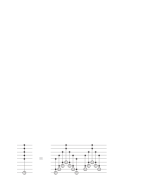
Consider NOT gates, similar to that in Figure 5, except with all the control bits being 1-controls (solid black dots in the figure). This gate applies the NOT operation to the target bit only if all the control bits are in state . We are shown how to simulate the NOT gate by Toffoli gates in [BBC+95]. For a circuit having a total of bits, if , and , the NOT operation can be simulated using Toffoli gates. Note that the construction in [BBC+95] does not require dedicated ancillary bits. The construction is illustrated for a specific example in Figure 6.
Consider the requirement that (i.e. no more than half of the bits on the circuit can be used as control bits). The addition circuit I will describe later (Figure 9) has bits (where is the size of each of and ) and the controlled NOT gates will only use up to control bits. So this technical requirement will be satisfied, and we can use the above result to count the depth of the NOT gates.
We wish to simulate a more general NOT gates such as those in Figure 5, where some of the control bits are 0-controls (hollow circles). To do this we have to add 2 to the overall depth, since we need to conjugate the 0-control bits with NOT gates, as in Figure 4. This means that the depth of a general controlled NOT gate is , where is the number of control bits (providing the technical requirement is satisfied).
3 A circuit for incrementing
A building block for the addition circuit is a circuit for incrementing an -bit number:
The circuit given in Figure 7 does this with one ancillary bit, initially set to 1. The ancillary bit will be known to equal 1 at the output of the circuit, and so can be re-used (e.g. for further incrementing). That is, the circuit in Figure 7 implements
To understand how the circuit in Figure 7 performs the incrementing, imagine how you would increment a binary number “by hand”. You would flip the least significant bit. If you had flipped it from a 0 to a 1, you would be done. If you had flipped it from a 1 to a 0, you would then proceed to flip the next most significant bit. You would proceed in this fashion until you had flipped a bit from 0 to 1, at which point you would be done. The ancillary bit in the circuit can be viewed as a “flag” which signals the first time you have flipped a bit from to , and should stop flipping bits. The flag is as long as you should continue flipping bits, and then is set to when the condition is reached such that you should stop flipping bits. We know that at some point we will have flipped the state of the flag bit from to , unless the state of the least significant bits was initially . In this case the state of these bits after incrementing is . So after incrementing , the flag bit should be re-set to by a NOT gate, unless . The portion of the circuit of Figure 7 surrounded by the dashed box accomplishes this uncomputing of the ancillary bit. Note that I originally proposed this incrementing circuit in [KZ04].
4 The addition circuit
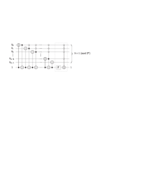
The addition circuit will make use of a sequence of controlled-incrementing circuits, . This will apply the incrementing circuit to an -bit register containing , conditioned on a single control bit equalling . Such a circuit can be realized by simply adding a control on to every gate in the incrementing circuit described above. The circuit and its abstract schematic symbol are shown in Figure 8.
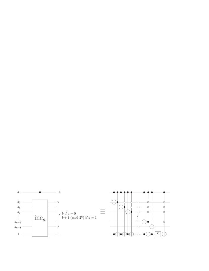
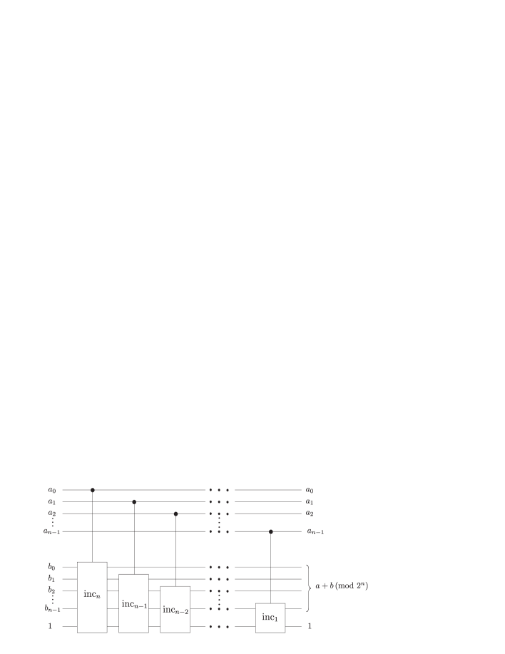
Now it can be seen that the circuit shown in Figure 9 performs the addition. The idea is that adding to modulo can be achieved by conditionally incrementing (mod ) the most significant bits of , controlled on , for . The single ancillary bit is left in the state at the end of the circuit, and so can be re-used.
5 Depth of the addition circuit
It remains to determine the depth of the addition circuit. The addition circuit uses a sequence of controlled incrementing operations. Let denote the depth of a controlled- operation. By carefully counting the depth of each of the general controlled NOT operations in the controlled- circuit, we find
Note that in the above calculation, I assumed that the controlled- operations will be in the context of a circuit having at least bits in total, so that the technical requirement of [BBC+95] is satisfied. This is true in the context of the addition circuit, which has bits (where is the size of and ).
For , the overall depth of the addition circuit is
6 Conclusion
We have seen how to perform in-place addition of two -bit numbers with only 1 ancillary bit by an -depth reversible circuit comprised of NOT, CNOT and Toffoli gates. After posting the original version of this note it was pointed out to me by C. Zalka that essentially the same technique for addition was used in [BCD+96]. The scenario in that paper was different, but it is clear how the technique they described generalizes to that in this paper.
The circuit in Figure 9 can be directly applied quantum states, provided we have a quantum implementation of the NOT, CNOT and Toffoli gates. In the language of quantum computing, the circuit would perform
The circuit depth of probably means that it would not be practical for classical (low power) computing [F04], but it may be practical for quantum computing if qubits are at a premium.
References
- [BBC+95] Adriano Barenco, Charles H. Bennett, Richard Cleve, David P. DiVincenzo, Norman Margolus, Peter Shor, Tycho Sleator, John Smolin, Harald Weinfurter, “Elementary gates for quantum computation”, Phys. Rev. A, 52:3457-3476, 1995. arXive e-print quant-ph/9503016.
- [BBF02] Stephane Beauregard, Gilles Brassard, Jose Manuel Fernandez. “Quantum Arithmetic on Galois Fields”. arXive e-print quant-ph/0301163.
- [BCD+96] David Beckman, Amalavoyal Chari, Srikrishna Devabhaktuni, John Preskill. “Efficient Networks for quantum factoring”. arXive e-print quant-ph/9602016.
- [CG75] Dan Coppersmith, Edna Grossman. “Generators for certain alternating groups with applications to cryptography”. SIAM J. Appl. Math., 29(4):624-627, Dec. 1975.
- [D00] Thomas G. Draper. “Addition on a Quantum Computer”. arXive e-print quant-ph/0008033.
- [DKR+04] Thomas G. Draper, Samuel A. Kutin, Eric M. Rains, Krysta Svore. “A Logarithmic-Depth Quantum Carry-Lookahead Adder”. arXive e-print quant-ph/0406142.
- [F04] Michael Frank, personal communication (2004).
- [FT82] E. Fredkin, T. Toffoli, “Conservative Logic”, Internat. J. Theor. Phys. 21, 219 (1982).
- [KZ04] P. Kaye, C. Zalka, “Optimized quantum implementation of elliptic curve arithmetic over binary fields”, e-print quant-ph/0407095.
- [VBE95] Vlatko Vedral, Adriano Barenco, Artur Ekert. “Quantum Networks for Elementary Arithmetic Operations”. Phys. Rev. A, 54:147, 1996. arXive e-print quant-ph/9511018.