Optimal Occulter Design for Finding Extrasolar Planets
Abstract
One proposed method for finding terrestrial planets around nearby stars is to use two spacecraft—a telescope and a specially shaped occulter that is specifically designed to prevent all but a tiny fraction of the starlight from diffracting into the telescope. As the cost and observing cadence for such a mission will be driven largely by the separation between the two spacecraft, it is critically important to design an occulter that can meet the observing goals while flying as close to the telescope as possible. In this paper, we explore this tradeoff between separation and occulter diameter. More specifically, we present a method for designing the shape of the outer edge of an occulter that is as small as possible and gives a shadow that is deep enough and large enough for a m telescope to survey the habitable zones of many stars for Earth-like planets. In particular, we show that in order for a m telescope to detect in broadband visible light a planet arcseconds from a star shining times brighter than the planet requires a specially-shaped occulter m in diameter positioned about km in front of the telescope.
1 Introduction
Since the first extrasolar planet was discovered by Mayor and Queloz (1995), various techniques have been used to infer the presence of large planets, but none have the capability to image Earth-like planets directly. Finding terrestrial planets is difficult because the difference in brightness between the star and the planet is so large; in the visible spectrum, the intensity difference, or contrast, is approximately (see Marais et al. (2002)). Just as importantly, the maximal angular separation between planet and star is on the order of arcseconds for a star 10 parsecs from Earth. The problem becomes one of reducing the intensity of starlight at the planet’s location by a factor of . Several methods (see Kasdin et al. (2003); Kuchner and Traub (2002); Vanderbei (2006); Guyon (2003)) have been proposed to do this within the telescope by adjusting the point spread function so that there is very little starlight at the location of the planet in the image plane of the telescope. While these techniques have demonstrated the potential to provide the necessary contrast (Sidick et al. (2006)), they have the intrinsic difficulty that they require an adaptive-optics system within the telescope to correct aberrations in the wavefront (induced largely by imperfect optics), which tend to spill unwanted light into the search area.
One solution to this problem is to remove the starlight before it reaches the telescope by using a second spacecraft, an occulter, positioned between the telescope and the target star. Such a concept was first proposed by Spitzer (1962); since then, a number of proposals (see Copi and Starkman (2000); Schultz et al. (2003); Cash (2006)) have appeared that use occulters to look for planets, both of Jupiter and Earth size.
Simple ray optics would suggest that a circular disk occulter of diameter would be adequate to block all of the starlight from entering a telescope of aperture . Unfortunately, this analysis neglects diffraction, which is a significant factor in propagations involving narrow angles. It was known as early as 1818 that diffraction around objects could produce light in areas that geometric optics would predict to be dark; the most notable example of this is Poisson’s spot, which earned Fresnel a prize from the French Academy of Sciences (see Goodman (1996)). A proper design of an occulter-based mission thus requires careful consideration of diffraction effects.
Spitzer (1962) noted that it was sufficient to change the transmission function with radius in order to suppress this central spot. Subsequent papers have suggested some specific mechanisms for accomplishing this. One concept, called the Big Occulting Steerable Satellite (BOSS) (Copi and Starkman (2000)), is based on a transmissive apodization defined by polynomials. A more recent entry into this field is the New Worlds Observer proposed by Webster Cash and funded by NIAC. Originally conceived as a pinhole camera in space (Simmons et al. (2004)), it was eventually reincarnated as a space-based occulter (Simmons (2005); Cash (2006)). There is some hope that an occulter mission, if technically feasible, could overcome the significant challenges that more traditional coronagraphic approaches to planet finding must confront. The purpose of this paper is to explore the trade-off between inner-working-angle and telescope-occulter separation. We show that an occulter capable of detecting in broad-band visible light an Earth-like planet at 60 mas separation from its parent star will need to be 50m in diameter (tip-to-tip) and fly 72,000 km in front of the telescope.
2 Babinet’s principle
An occulter is complementary to a pinhole camera; instead of allowing light only through a small hole, an occulter allows all light except for the light blocked by the occulter which now replaces the small hole. This complementarity allows us to calculate the downstream electric field produced by an occulter using Babinet’s principle; that is, the sum of the light passing around the occulter and the light passing through an occulter-shaped hole is a free-space plane wave. The electric field past the occulter is thus given by
| (1) |
where is the field produced by an occulter, is the electric field of an unobstructed plane wave, and is the field produced by a complimentary pinhole. From the Helmholtz equation it follows that a plane wave having complex amplitude at the plane of the occulter would, if unimpeded by an occulter, be given by at the telescope’s pupil plane, which is located a distance behind the occulter. Here, and throughout the paper, we use polar coordinates to represent the pupil plane of the telescope. We assume that corresponds to the center of the pupil.
Before we investigate simple shaped occulters, it is instructive to consider a more general setting in which an occulter (or a hole) need not be purely opaque or transparent. Instead, we introduce the possibility for partial attenuation. To this end, we introduce a function to denote the attenuation profile for the occulter (we use and to denote polar coordinates in the plane of the occulter). If takes the value somewhere, then no light gets through at that point. On the other hand, if it takes the value zero, then all light gets through. All values in between are allowed. Under circular symmetry, the attenuation profile does not depend on and so we can write for the attenuation profile. Of course, when thinking about transmission through a “tinted” hole, the function represents the level of transmission rather than attenuation. That is, describes an apodization of the hole. With these assumptions, at the occulter plane can be written as
| (2) |
Assuming that the function is zero for larger than some threshold , the Fresnel integral for the propagation of the field from the hole a distance can then be written in polar coordinates (Goodman (1996)) as
| (3) |
and the field due to an occulter can be expressed as
| (4) |
3 Optimal attenuation functions
We find by minimizing the “extent” of subject to the constraint that the intensity, which is the square of the magnitude of the electric field, in a specified dark region is no more than . To be precise, we
| minimize | |||||
| subject to | (5) | ||||
This is an infinite-dimensional, quadratic programming problem, which would produce a shadow from to with contrast at the telescope’s pupil plane. Unfortunately, it is computationally intractable. To make it solvable, we introduce certain simplifications to reduce it to a finite-dimensional, linear programming problem.
First, we rewrite the constraint on as:
| (6) |
Since is complex, we can constrain the magnitude of the real and imaginary parts of to be less than or equal to to get a more conservative, but linear, constraint on . Finally, we discretize and to get a finite-dimensional program.
As formulated, this optimization model produces the desired shadow only at a single selected wavelength. For such an optimization model, the “optimal” function turns out to take on only two values: zero and one. In other words, the solution is a concentric ring mask (see Vanderbei et al. (2003b)). Such a solution achieves the desired contrast at the specified wavelength, but its performance degrades quickly as one moves either to longer or shorter wavelengths. To find a design that works over a broad band of wavelengths, we make a few simple changes to our optimization model. Obviously, the first change is to stipulate that the function provide a dark shadow at multiple wavelengths. Hence, the contrast constraints are repeated for a discrete set of wavelengths that span the set of wavelengths for which a shadow is desired. Of course then one needs to worry about the gaps between the chosen discrete set of wavelengths. One possibility is simply to require the shadow to be darker than necessary at the chosen wavelengths with the thought that the performance can’t degrade with arbitrary abruptness as one moves to intermediate wavelengths. But, a better solution is to impose smoothness constraints on the function . If this function is smooth, then one expects the shadow to remain deep longer as one moves away from the specified wavelengths. A simple way to impose smoothness is to place a bound on the magnitude of the second derivative
Such constraints help, but it turns out that the best thing to do is to let be an optimization variable and minimize this bound on the smoothness:
| minimize | |||||
| subject to | (7) | ||||
(the original objective of minimizing the integral of actually has little effect on the problem as long as is small enough). Of course, once we introduce a shadow constraint for each of several wavelengths, we have the freedom to let the depth and width of the shadow be wavelength dependent.
Practical considerations also provide further constraints. For a realistic binary occulter, the innermost section should be opaque out to some radius to accommodate the spacecraft. This is expressed as:
| (8) |
We might also wish to impose the constraint that as this will ensure that the petal-mask to be described next will have petals that get monotonically narrower as one moves out to the tip. Such petal shapes are probably easier to manufacture.
4 Adding petals
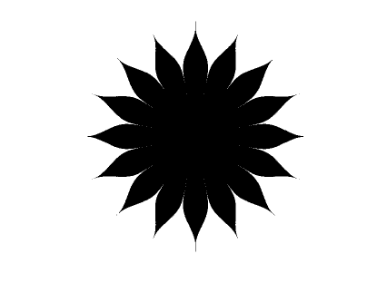
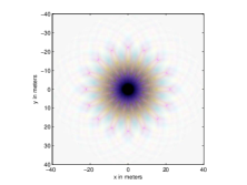
Unfortunately, it is not currently possible to build an apodized occulter to the required precision. So, instead, we replace the apodized occulter with a binary occulter of a particular shape. For instance, inspired by Vanderbei et al. (2003a), Cash (2006) suggested using an occulter made up of a set of N identical evenly spaced “petals” as shown in Figure 1. These petals are wedges of the circle whose width varies with radius such that the fractional angular extent of the occulter at a given radius is the attenuation profile . Except for Babinet’s principle, this petal-shaped occulter is identical to the starshaped pupil masks described in Vanderbei et al. (2003a). The resulting propagated field for such an occulter is thus found via the same procedure using the Jacobi-Anger expansion. The result is
| (9) | |||||
where is the field from the smooth apodization and N is the number of petals (assumed even). For large , all of the () become small exponentially fast near the center of the telescope and so the field approaches that of the smooth apodization as increases.
5 Results
One consideration that must be taken into account when designing optimized occulters is angular size of the shade. As mentioned in Sec. 1, the maximum angular separation between Earth-like planets and their stars is 0.1 arcsecond for a star 10 parsecs distant. The angular size of the shade is . For example, for a m radius shade, the shade must be at least km distant. If we want to see planets at smaller angular separations, i.e., further from Earth, the shade must be shrunk or the distance increased. We present a series of shades optimized with different sizes and at different distances.
Radially-symmetric apodizations were created to provide contrast out to a given radius for four separate occulter profiles:
18m occulter, 18000 km distance, 3m shadow radius
20m occulter, 36000 km distance, 3m shadow radius
25m occulter, 72000 km distance, 2.5m shadow radius
30m occulter, 100000 km distance, 2.5m shadow radius
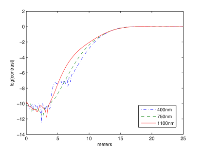
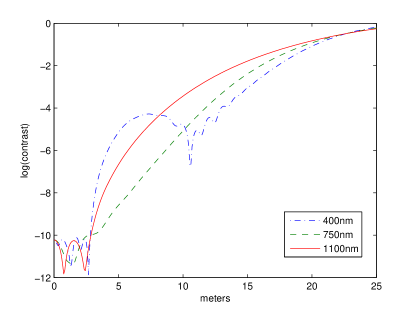
These occulters were designed to provide the specified contrast over a band from nm to nm with contrast constraints specified in nm increments across this band. Radial profiles of the shadow at the telescope are shown in Fig. 2. The profiles are shown for three wavelengths: nm, nm, and nm. Note that these wavelengths correspond to the shortest and longest wavelengths at which high contrast was dictated as well as an intermediate wavelength which happens to fall midway between the two nearest wavelengths at which high contrast was constrained (nm and nm).
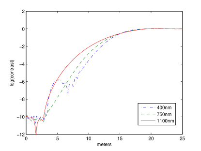
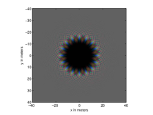
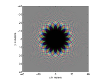
Once a profile is created by optimization, we use Eq. 9 to calculate the effect of converting a smooth apodization to petals; this petalization tends to reduce the width of the shadow at certain angles. In a forthcoming paper, we will present a method of optimizing the petal shape directly, to prevent this degradation. Each of the four occulters was converted to a binary occulter with petals; the performance of these occulters at nm, nm, and nm is shown in Fig. 3.
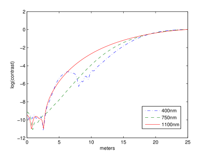
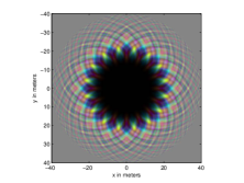
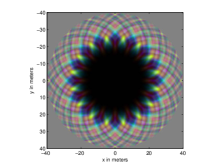
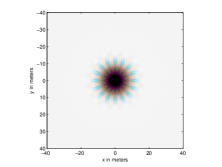
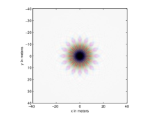
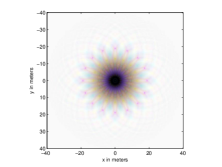
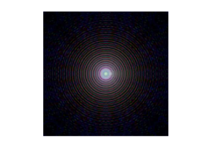
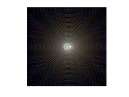
Finally, some may suggest that it is overly conservative to insist on contrast at the telescope’s pupil plane since additional contrast is generated by the telescope itself as it forms an image. The residual starlight, being roughly flat across the telescope’s pupil, forms something similar to an Airy pattern in the image plane. The planet will be slightly off-axis and therefore offset slightly from the on-axis Airy pattern. Since the first diffraction ring in an Airy pattern is almost two orders of magnitude suppressed relative to its main lobe, one can expect some benefit. To test this, we modified our optimization code to minimize an upper bound on the intensity of the light over a m diameter shadow. We ran tests assuming various separations . The tip radius was fixed so that the a planet appearing at the tip is arcseconds off-axis (i.e., we set radians equal to milliarcseconds and solved for ). The smallest value of that provides a sufficiently dark hole for the planet to be detectable in the image plane turns out to be km. For this case, the shadow at the telescope’s pupil is slightly brighter than times the unattenuated brightness. In the image plane, a planet at milliarcseconds has about the same brightness as the residual starlight falling in the same location in the image (a detection in TPF parlance). Figure 4 shows image plane images for the km design described here. Also shown in the figure for comparison is the image plane image for the km design described earlier.
6 Final Remarks
Whenever one uses optimization for engineering design, an important question to address is this: how sensitive is the optimal design to small deviations from the given design scenario? We have already discussed some of our efforts to ensure that our design is robust. Namely, we have discussed the issue of specifying shadow depth at several wavelengths spread across the desired waveband and we have discussed using smoothness of as a surrogate for solution robustness. Furthermore, we have shown plots that verify the shadow depth at two contrast-specified wavelengths (nm and nm) as well as at a wavelength at which contrast was not specifically constrained but instead is midway between two such wavelengths. In all three of these cases the depth of the shadow proves to be more than adequate.
There are further robustness issues that need to be investigated. For example, how deep will the dark shadow be if the occulter-telescope separation deviates from the design value by a few percent? Also, to what precision do the petals need to be manufactured and then deployed? Finally, how much can the occulter’s orientation be tilted relative to the occulter-telescope axis? Regarding the second question, preliminary analyses in which we randomly perturbed by one part in and recomputed the shadow profiles showed that perturbations at this level do not degrade the depth or size of the shadow. On the other hand, perturbations at the level of one part in do start to affect performance. Anyway, these are just very preliminary results. All of the above questions are important and will be addressed in detail in a forthcoming paper.
In this paper we have used optimization techniques to investigate the trade-off between inner working angle and size/distance of the occulter. For terrestrial planet finding, it seems that the inner working angle should be no more than 60 mas. The number of Earth-like planets one can hope to find drops quickly as one moves to larger separations. We have shown that, for an inner working angle 60 mas, the occulter needs to be about 50 m tip-to-tip and it must be positioned about 72,000 km in front of the telescope. Future studies should be directed at determining whether such a size and distance combination can be achieved within a reasonable mass and fuel budget.
References
- Cash (2006) W. Cash. 2006, Detection of earth-like planets around nearby stars using a petal-shaped occulter. Nature, 442, 51
- Copi and Starkman (2000) C.J. Copi and G.D. Starkman. 2000, The Big Occulting Steerable Satellite [BOSS]. ApJ, 532, 581
- Goodman (1996) J.W. Goodman. 1996, Introduction to Fourier Optics. McGraw-Hill
- Guyon (2003) O. Guyon. 2003, Phase-induced amplitude apodization of telescope pupils for extrasolar terrestrial planet imaging. A & A, 404, 379
- Kasdin et al. (2003) N.J. Kasdin, R.J. Vanderbei, D.N. Spergel, and M.G. Littman. 2003, Extrasolar planet finding via optimal apodized pupil and shaped pupil coronagraphs. ApJ, 582, 1147
- Kuchner and Traub (2002) M.J. Kuchner and W.A. Traub. 2002, A coronagraph with a band-limited mask for finding terrestrial planets. ApJ, 570, 900
- Marais et al. (2002) D.J. Des Marais, M.O. Harwit, K.W. Jucks, J.F. Kasting, D.N. Lin, J.I. Lunine, J. Schneider, S. Seager, W.A. Traub, and N.J. Woolf. 2002, Remote sensing of planetary properties and biosignatures on extrasolar terrestrial planets. Astrobiology, 2(2), 153
- Mayor and Queloz (1995) M. Mayor and D. Queloz. 1995, A jupiter-mass companion to a solar-type star. Nature, 378, 355
- Schultz et al. (2003) A.B. Schultz, I.J.E. Jordan, M. Kochte, D. Fraquelli, F. Bruhweiler, J.M. Hollis, K.G. Carpenter, R.G. Lyon, M. DiSanti, C. Miskey, J. Leitner, R.D. Burns, S.R. Starin, M. Rodrigue, M.S. Fadali, D. Skelton, H.M. Hart, F. Hamilton, and K.-P. Cheng. 2003, UMBRAS: A matched occulter and telescope for imaging extrasolar planets. In Proceedings of SPIE–High-Contrast Imaging for Exo-Planet Detection, volume 4860
- Sidick et al. (2006) E. Sidick, F. Shi, S. Basinger, D. Moody, A.E. Lowman, A.C. Kuhnert, and J.T. Trauger. 2006, Performance of TPF’s high-contrast imaging testbed: modeling and simulations. In Proceedings of SPIE–Space Telescopes and Instrumentation I: Optical, Infrared, and Millimeter, volume 6265
- Simmons et al. (2004) W. L. Simmons, W. C. Cash, S. Seager, E. Wilkinson, N. J. Kasdin, R. J. Vanderbei, N. Chow, E. Gralla, and J. Kleingeld. 2004, The New Worlds Observer: a mission for high-resolution spectroscopy of extra-solar terrestrial planets. In Microwave and Terahertz Photonics. Edited by Stohr, Andreas; Jager, Dieter; Iezekiel, Stavros. Proceedings of the SPIE, Volume 5487, pp. 1634-1645 (2004)., pages 1634 10.1117/12.552069.
- Simmons (2005) W.L. Simmons. 2005, A pinspeck camera for exo-planet spectroscopy. Technical report, M.S. Thesis, Department of Mechanical and Aerospace Engineering, Princeton University
- Spitzer (1962) L. Spitzer. 1962, The beginnings and future of space astronomy. American Scientist, 50, 473
- Vanderbei (2006) R.J. Vanderbei. 2006, Diffraction analysis of two-dimensional pupil mapping for high contrast imaging. ApJ, 636, 528
- Vanderbei et al. (2003a) R.J. Vanderbei, D. Spergel, and N.J. Kasdin. 2003a, Circularly symmetric apodization via star-shaped masks. ApJ, 599, 686
- Vanderbei et al. (2003b) R.J. Vanderbei, D.N. Spergel, and N.J. Kasdin. 2003b, Spiderweb masks for high contrast imaging. ApJ, 590, 593