Microstrip resonator for microwaves with controllable polarization
Abstract
In this work the authors implemented a resonator based upon microstrip cavities that permits the generation of microwaves with arbitrary polarization. Design, simulation, and implementation of the resonators were performed using standard printed circuit boards. The electric field distribution was mapped using a scanning probe cavity perturbation technique. Electron spin resonance using a standard marker was carried out in order to verify the polarization control from linear to circular.
Electron paramagnetic resonance (EPR) is a well established tool for assessing the electron spin degree of freedom in paramagnetic centers in a variety of systems. EPR has been traditionally used to investigate their response to an applied magnetic field and to map the corresponding symmetries inside crystalsabragam ; poole . More recentlyNV_Diamond , optically detected magnetic resonance (ODMR) on single centers has been used to carry out manipulation of spin states targeting the implementation of prototypical architectures for quantum information processing (QIP) devices. State preparation, manipulation and read-out can be accomplished by proper choice of microwave and optical stimuliNV_Diamond . Nevertheless, for adequate QIP implementations it is important to further improve the ability to select and tune the transitions; for example, Stark shifting levels associated with optical transitions may allow better coupling with optical cavitiestamarat06 .
The design of microwave cavities has a direct impact on the prospects of spin resonance apparatus applied to QIP. In addition to improving the quality factor, which allows for greater sensitivity poole , polarization control of the excitation stimulus can provide additional functionality for experimental set-ups. An application for polarization controlled microwaves concerns the selective excitation of spin transitions, which may impact state preparation at zero magnetic fieldsalegre_07 . Also the determination of the g-factor signchang requires circularly polarized microwaves. This has been an issue of recent debate concerning electron spins in quantum dots pryor05 ; bayer06 , which bears significant importance to solid state QIP. Earlier work on generating circularly polarized microwaves employed cylindrical cavities coupled to waveguides through an iris galt55 ; clyde ; suematsu ; chang ; filter . Later, a square cavity pumped by two 90∘ out-of phase signals was successfully employed to generate circularly polarized microwavediaz . These implementations required mechanical adjustments for polarization control, which may pose difficulties for the generation of arbitrary polarization of microwaves, or even polarization modulation.
In this work we designed and fabricated a two-port microstrip resonator implemented by patterning a half-wavelength resonator onto a dielectric substrate with a ground plane that allows for arbitrary control of the microwave polarization. This was experimentally verified by carrying out EPR experiments with samples containing a conventional marker with known g-factor.
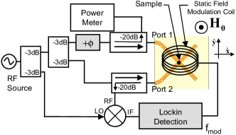
Resonators were fabricated after simulation utilizing Ansoft HFSS software ansoft on printed circuit boards (PCB) through conventional photolithography. PCBs (Rogers model RO 3203) with a relative permittivity were utilized. The spatial distribution of the z component of the electric field, , was mapped by means of a scanning probe cavity perturbation technique. A 300m diameter, 8 mm long electrochemically sharpened tungsten tip was scanned 250m over the resonator surface and the cavity response was concomitantly monitored with a vector network analyzer. The intensity of the field can be directly related to the shift of the natural frequency of the cavity when perturbed by the metallic tiprf_book ; maier . The EPR set-up consisted of a standard dc magnet with field modulation supplied by an additional coil, and a solid state microwave source. The two ports of the resonator were pumped independently and the phase between the excitation signals could be adjusted by a phase shifter with negligible insertion loss. The reflected signal was Lock-in detected using a mixer operating as a linear detectorpoole (Fig. 1). The experiments were performed at room temperature utilizing DPPH (1,1-diphenyl-2-picrylhydrazyl, g=2.00360.0003poole ) as the spin marker.
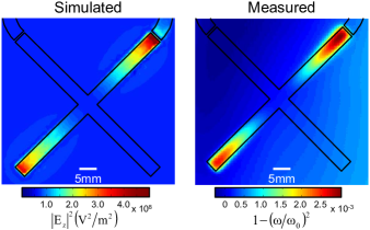
By placing two half-wavelength resonators orthogonally, one can control the direction and polarization of the fields at their intersection by adjusting the amplitude and phase of the excitation signal at each port. The zeroth order mode of the proposed resonator consists of two degenerate and orthogonal modes (i.e., the superposition of the quasi and modes) that can be pumped independently by two oscillators with an arbitrary phase difference, thereby creating the desired degree of polarization. For the half-wavelength resonator a first estimate for the resonance frequency can be evaluated by , where is the cavity mode, the speed of light in vacuumjohansson74 ; silesbee91 . In the case of the two port resonator, the first mode frequency should not be too far from this estimate. For a resonator fabricated on the PCB with an arm length of 5.5 cm we obtained the first mode resonance at a frequency of . The electric field can be associated to the shift in the resonance frequency of the cavity by , where , and are the perturbed frequency, natural frequency and a geometrical factor that takes into account the shape of the perturbing object and the volume occupied by the electromagnetic fieldrf_book ; maier . Fig. 2 shows the spatial distribution of the electric field for one of the degenerate modes, calculated and imaged at 1.71GHz (displayed as ). This mode has two important characteristics: a) it has a node for the electric field at the center of the cavity, which is essential for EPR experiments in quantum dots klaus06 ; koppens06 ; this fact also enables the investigation of highly conductive samples without loading the cavity; b) there is a good isolation (50dB) between this mode and the orthogonal, degenerate mode (not shown); this permits independent pumping of the resonator, which is crucial for polarization control. The agreement between the experiment and calculation is qualitative differing by a multiplying factor rf_book ; maier ; nevertheless, the scanning probe perturbation method allows us to identify the ideal spot to place the sample.
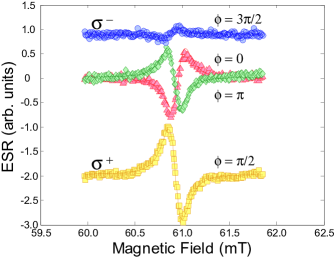
In order to evaluate the degree of polarization, we performed EPR experiments. By measuring the EPR signal as a function of the phase difference between the microwave stimuli at the two ports, one can determine whether the polarization is linear, circular or elliptical. The DPPH sample was positioned at the center of the cavity where the circularly polarized microwave reaches the maximum degree of polarization and intensity. Fig. 3 shows the EPR signal for DPPH for and . For , the signal amplitude does not change, which confirms linear polarization for the microwaves; the orientation of is parallel and perpendicular to the -axis (see Fig. 1), respectively. This creates a phase shift in the detected signal. For , the amplitude of the EPR signal is maximum, in accord with polarization, since the g-factor for DPPH is positive. As expected, for ( polarization), the EPR signal is minimum.
One can define the degree of polarization by , where are the signal amplitudes for polarization. We find . The fact that the microwaves are not polarized can be attributed to: a) slight differences of power and phase at each port due to imperfections of the connectors and cables; b) the geometry of the intersection of the two arms is not circular, but rather a square; this will produce spatial harmonics and the circular polarization is present only at one point at the very center of the resonator; c) imperfections in the fabrication of the resonator, in particular the coupling gap (200m in width), which can produce phase differences. These problems can be eliminated by external trimming of the amplitude and phase of the incoming microwaves and using smaller samples.
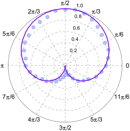
Finally, Fig. 4 shows the EPR signal amplitude as a function of the phase difference between the microwave stimuli at each arm. This dependence can be shown to be , which is represented in the polar plot by the solid line. This graph demonstrates the ability of creating arbitrary polarization, from linear to circular, with a degree of polarization better than 80% for any desired combination of linear and circular polarization.
In summary, we successfully designed and implemented a resonator that allows one to produce arbitrarily polarized microwaves. This resonator can in principle produce microwaves with time-dependent polarization modulation, by either adjusting the phase or the amplitudes at each arm. We also employed an electric field mapping technique to spatially locate the resonator modes, thus allowing an optimum choice of a suitable mode for polarization control. For the modes where the electric field has a node at the cavity mid-point, the loading of the resonator is minimal, which can be quite advantageous in applications where an electric contact to the sample is required. Additionally, by choosing a material with high dielectric permittivity, the resonators can be made very compact which can be easily integrated in systems where space is a constraint. These devices represent interesting perspectives for the implementation of experiments which require polarization control of microwaves, including for example the determination of the electronic g-factor sign and transition selection rules.
We acknowledge the financial support by FAPESP process number 04/01286, CNPq and HP-Brazil. The authors would like to thanks the technical assistance of M. H. Piazzetta and A. L. Gobbi from the micro-fabrication facility at LNLS for help with the fabrication of the resonators.
References
- (1) Electron Paramagnetic Resonance of Transition Ions, A. Abragam, Clarendon Press, Oxford, 1970.
- (2) Electron Spin Resonance, Charles P. Poole, Jr., Dover Publications, Inc,1996.
- (3) M.V.G. Dutt, L. Childress, L. Jiang, E. Togan, J. Maze, F. Jelezko, A.S. Zibrov, P.R. Hemmer, and M.D. Lukin, Science, 316, 1312 (2007); C. Santori, P. Tamarat, P. Neumann, J. Wrachtrup, D. Fattal, R.G. Beausoleil, J. Rabeau, P. Olivero, A.D. Greentree, S. Prawer, F. Jelezko, and P. Hemmer, Phys. Rev. Lett. 97, 247401 (2006).
- (4) Ph. Tamarat et al., Phys. Rev. Lett. 97, 083002 (2006).
- (5) T. P. Mayer Alegre, C. Santori, G. Medeiros-Ribeiro, and R. G. Beausoleil, arXiv:0705.2006
- (6) Te-Tse Chang, Phys. Rev. 136, A1413 (1964).
- (7) C. E. Pryor and M. E. Flatté, Phys. Rev. Lett. 96, 026804 (2006).
- (8) I. A. Yugova, et al. Phys. Rev. B 75, 195325 (2007).
- (9) J. K. Galt, W. A. Yager, F. R. Merritt, B. B. Cetlin and H. W. Dail, Phys. Rev.100, 748 (1955).
- (10) Clyde A. Hutchison and Bernard Weinstock, J. Chem. Phys. 32, 56 (1960).
- (11) Hiroyoshi Suematsu, Rev. Sci. Instrum. 45, 445 (1974).
- (12) Generation of circularly polarized microwaves utilizing cylindrical cavities can find applications in reflectionless filters, e.g. C.E. Nelson, IRE Trans. Microwave and Tech., 5, 136 (1957).
- (13) J. Diaz, S. Haraldson, U. Smith and L. Pettersson, Rev. Sci. Instrum. 45, 454 (1974).
- (14) www.ansoft.com
- (15) Microwave Measurements, Edward L. Ginzton, McGraw-Hill, New York, 1957.
- (16) L. C. Maier, Jr. and J. C. Slater, J. Appl. Phys. 23, 68 (1952).
- (17) W. J. Wallace and R. H. Silsbee, Rev. Sci. Instrum. 62, 1754 (1991).
- (18) B. Johansson, S. Haraldson, L. Pettersson, and O. Beckman, Rev. Sci. Instrum. 45, 1445 (1974).
- (19) B. Simovic et al., Rev. Sci. Instrum. 77, 064702 (2006).
- (20) F. H. L. Koppens, et al., Nature 442, 766 (2006).