Manganites Colossal magnetoresistance Disordered solids
Exploiting B Site Disorder for Phase Control in the Manganites
Abstract
Disorder on the active element site is usually very disruptive for conduction and long range order in perovskite transition metal oxides. However, in the background of phase competition such ‘B site’ dopants also act to promote one ordered phase at the expense of another. This occurs either through valence change of the transition metal or via creation of ‘defects’ in the parent magnetic state. We provide a framework for understanding the complex variety of phenomena observed in B site doped manganites and identify the key parameters that control the physics. Using a spatially resolved analysis of B ions in various manganite phases we explain the existing data and predict new situations where highly polarisable phase separated states can be created.
pacs:
75.47.Lxpacs:
75.47.Gkpacs:
72.80.NgCorrelated electron systems like the cuprates and manganites involve competition between various long range ordered phases [1, 2]. The interplay of this phase competition with weak disorder underlies phenomena like cluster coexistence, percolative transport, and colossal response. The nature of disorder seems to be crucial for these effects, as observed in the manganites [2], and a low concentration of impurities on the active element site is an effective trigger for phase separation [3, 4, 5, 6, 7, 8, 9, 10, 11, 12] and the associated percolative effects.
The results of such substitution depend on the reference state and the chemical nature of the impurity. For manganites, with rare earth (RE) and alkaline earth (AE) combination RE1-xAExMnO3, several intriguing results exist for Mn site doping. Magnetic dopants like Cr [3, 4, 5, 6, 7], Co or Ni [8] (but not Fe) on the Mn site in a charge ordered insulating (CO-I) manganite promote a percolative ferromagnetic metal (FM-M), while non magnetic dopants of the same valence do not. The orbital ordered A type antiferromagnet (AF) at is destabilised in favour of a ferromagnetic state [9] by both magnetic and non magnetic dopants. In contrast to the cases above, where charge-orbital order is suppressed, doping Fe on a ferromagnetic metal [10, 11] at promotes a charge ordered insulating state! On spatial imaging most of these systems reveal phase separation (PS) and many of them also exhibit enormous magnetoresistance. It is vital to uncover the organising principle behind this diversity of effects, if we are to exploit B site disorder as a tool for phase control.
There is unfortunately no microscopic model, let alone a theory, for randomly located B dopants in the manganites. In this paper we write down the first detailed model for B impurities in a manganite host, and study the effect of these dopants in a variety of manganite phases using a real space Monte Carlo technique.
Our principal results are the following: (i) We discover that the following hierarchy of effects arise in all B doping cases: (a) change of the effective valence on the Mn sites, (b) percolation of the metallic phase through impurity free regions, and (c) ‘reconstruction’ of the background magnetism and charge order by magnetic dopants. (ii) By exploring the prominent manganite states, and different B dopants, we are able to explain most of the outstanding experimental results. (iii) We suggest a new experiment to test out an unexplored insulator-metal transition driven by B site disorder. (iv) We demonstrate how B impurity locations determine the percolation pattern and may allow atomic level control of current paths in a material.
The simplest classification of B site dopants is in terms of their valence in the manganite host. Among the usual dopants Zn, Mg, and Co, are divalent, i.e, in a state, Ni, Cr, Fe, Sc, and Al are trivalent, while Ru, Sn, and Ti are tetravalent. Some elements can exist in multiple valence states, e.g, Ni can also be , and Ru can be , but that will not affect our qualitative arguments. The valence, , of the dopant affects the effective carrier density on the Mn sites through the charge neutrality requirement on the compound REAEMnBO, where is the % of B site doping, and we write the Mn valence as . This yields . The effective electron count on Mn is , modified from at . This change of effective carrier density can itself drive phase change as we will see later. Secondly, dopants with same valence can have different effects depending on their magnetic character. Non magnetic dopants only affect the Mn valence, while those with partially filled shells can have magnetic coupling to the neighbouring Mn moments. Experiments suggest that Cr has strong AF coupling [13] to the Mn ions, Ni couples ferromagnetically [13], while Fe, despite its magnetic configuration, couples rather weakly.
Based on the inputs above we construct the following model for manganites with B site dopants: , with
| (2) | |||||
| (3) | |||||
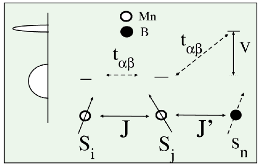
The reference ‘manganite model’ is constructed to reproduce the correct sequence of phases in the ‘clean’ limit. It involves the nearest neighbour hopping of electrons with amplitude [14], Hund’s coupling , AF superexchange between Mn spins, and Jahn-Teller (JT) interaction, , between the electrons and the phonon modes . The stiffness of the JT modes is . We will not consider RE-AE cation disorder in since such ‘A site’ disorder masks the B site effects. The sites and operator refer to Mn locations, and , etc, are Mn spins. The local physics of the B ions is contained in where refers to the B locations and the operators refer to the B ion states at an energy above the center of the Mn band. The sites are random, with only the constraint that two B dopants are not nearest neighbours, to minimise electrostatic repulsion. involves hopping matrix elements , which we keep the same as between the Mn, for magnetic B ions, a superexchange coupling between the B moment and the neighbouring Mn moments, and a nearest neighbour Coulomb repulsion between the B dopant and the neighbouring Mn. The total charge on the Mn ion is , where is the occupancy, and is the (fixed) B ion valence. Fig.1 is a schematic, showing the relevant levels on Mn and B, and the coupling between these atoms. Earlier attempts at modelling B dopants (or Mn vacancies) only employed a random onsite potential [15].
The overall carrier density is controlled through the chemical potential term: . We use the standard limit , and set . In studying magnetic field effects we will use a coupling , where is the applied field. We treat all spin and phonon degrees of freedom as classical [16], and measure all energies in units of the Mn-Mn hopping [14]. The spins, , etc, are treated as unit vectors, and the magnitude of the spin is absorbed in the couplings and .
The parameter space of the problem is very large. We have to contend with manganite states at different doping , different (inverse) bandwidth , and AF strength . The impurities are characterised by their concentration , the level , and the magnetic coupling . We use as a typical JT coupling, (to capture the correct phase competition around ), and [17]. We will explore several doping levels , and and study the effect of a low density of B dopants.
We use a Monte Carlo (MC) technique based on the ‘travelling cluster approximation’ (TCA) [18].
It allows ready access to system size using a moving cluster of size , and handles disorder accurately. The method, and the associated transport calculation, has been extensively benchmarked by us and used successfully in several earlier studies [14, 19].
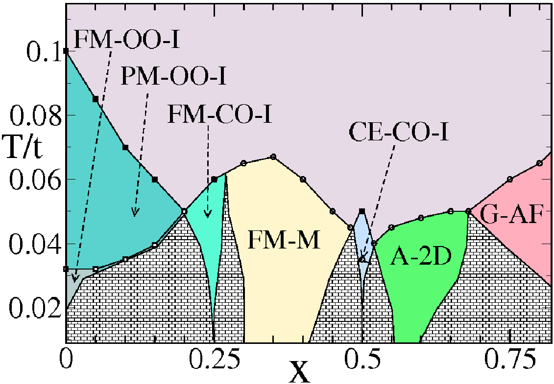
The first principle that we wish to illustrate is phase separation driven by change in effective carrier density. Fig.2 shows the phases in for varying ‘hole density’ . The phases, in increasing order of , are an orbital ordered insulator at [19], a ferromagnetic charge ordered insulator (FM-CO-I) at , a FM-M window between , the CE-CO insulator at , and a magnetic phase (‘A-2D’), with structure factor peaks at , between . Between these phases are the shaded windows of PS. If the carrier density is in one of these PS windows the system would break up into coexisting patches of the two adjacent phases. For a system at the edge of PS a small valence change driven variation in the carrier density can push it into the PS window. Fig.2 shows many such possibilities. These can be exploited by choosing dopants of suitable valence. The tendency towards large scale PS competes with the fragmenting effect of disorder, leading finally to a percolative state.
Let us start with . In the clean limit the orbital ordered (OO) JT insulator at [19] is separated from the FM-CO-I at by a wide PS window. The FM-CO-I can be looked upon as the charge ordering of doped holes with double the lattice periodicity in both and directions. In Fig.2 the phase is bounded on the right also by a PS window, which separates it from the homogeneous FM-M. To ‘metallise’ the phase we need impurities that decrease the effective electron density, pushing it towards the FM-M. From our expression for at low we obtain , so any impurity with valence will serve to lower and push the system into the PS window. The system could then phase separate, with FM-CO-I and FM-M clusters whose pattern is controlled by the B ion locations.
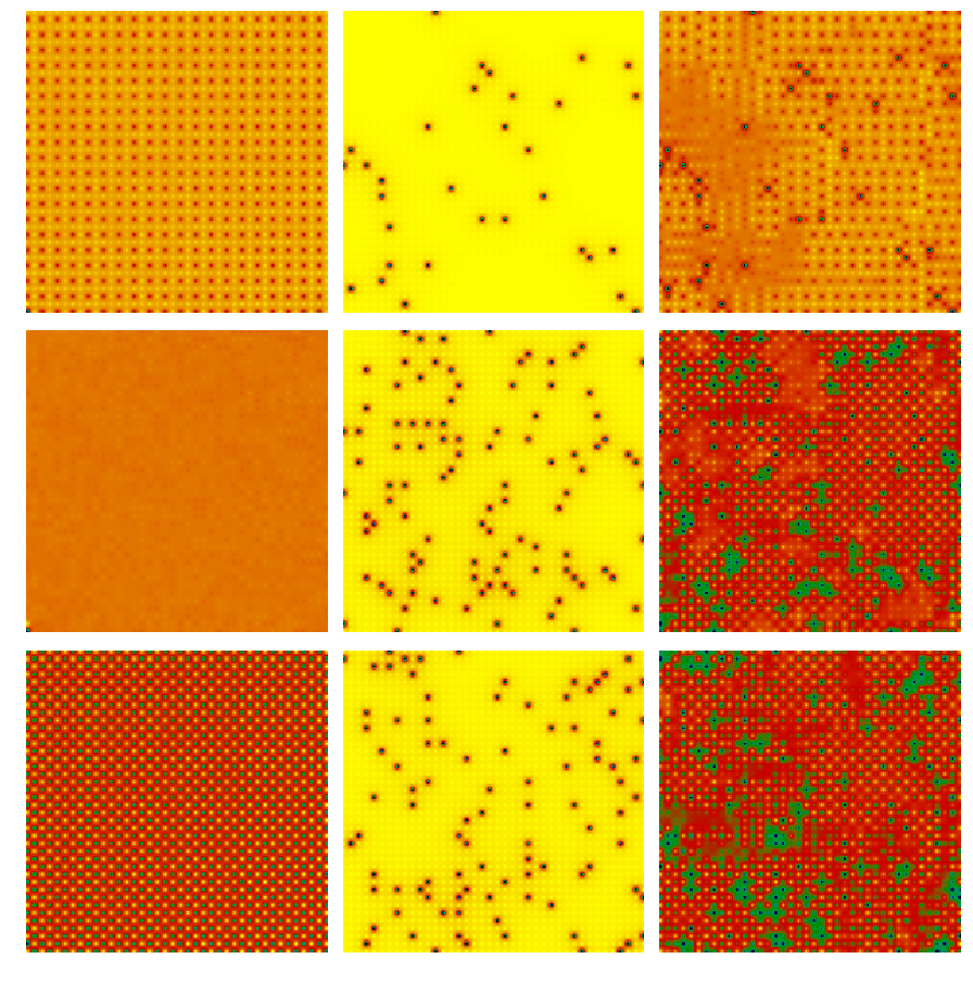
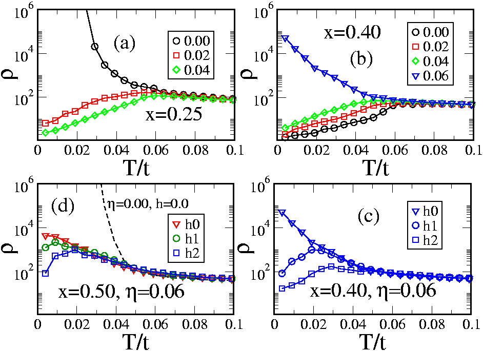
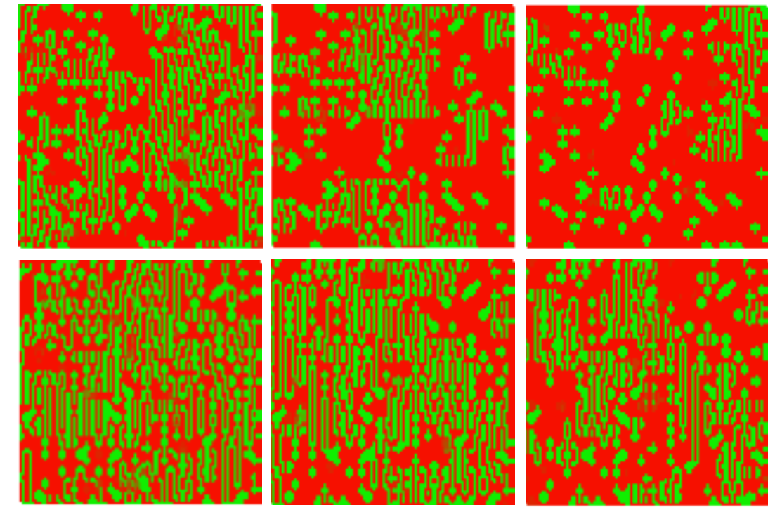
Fig.3 top row shows a snapshot of the charge density field in the reference CO state at (left), followed by the impurity locations (center), and (right) in the presence of the B ions. The impurities are non magnetic , divalent, with (which is roughly half the Mn bandwidth) and . Trivalent impurities yield similar results. The emergence of homogeneous regions of () coexisting with short range (SR) CO patches is clear. The FM-M live in the ‘impurity free’ regions, while the SR-CO can coexist with the impurities at short distance but loses coherence at larger scales. The percolation of the FM-M patches creates a ‘global’ metallic state. Fig.4.(a) show the evolution of the resistivity with . Since both the reference CO phase and the emergent metal are FM we cannot get any magnetoresistance in this regime. It would be interesting to choose in the (La1-yPry)0.75Ca0.25MnO3 family so that the material is at the insulator-metal phase boundary, and explore the impact of or B dopants.
Let us shift to which is next to the PS window separating the FM-M from the CE-CO-I phase. The reference state is a homogeneous metal.
We explore the impact of non magnetic divalent dopants with on this state, and push into the PS window. Such a situation had been explored experimentally early on by doping Mg [12] onto Pr0.7CaySr0.3-yMnO3. A metal-insulator transition in the ground state was seen with increasing Mg doping. Similar results were observed on doping Fe [10] (which is a dopant with weak magnetic coupling) into La1-xCaxMnO3 at .
The left panel in the middle row in Fig.3 shows the ‘flat’ profile of in the undoped FM-M state. The central panel shows the dopant locations at and the right panel shows the in the presence of dopants. The final shows local charge order arising out of ‘disordering’ the FM-M! This has indeed been reported [11] recently. The FM order in the ground state is significantly suppressed with increasing , and Fig.4.(b) shows the low metal-insulator transition driven by B site doping. Fig.4.(c) shows the dramatic suppression in resistivity of this PS system, at , in response to a magnetic field. The disorder driven insulating state can be readily ‘metallised’ by a modest field.
Just as depleting the electron density converts the ferromagnetic metal at to a FM-M+AF-CO-I phase separated state, we can explore the effect of increasing the electron density on the CE state at . Since it is obvious that dopants like Ru or Sn, with valence , will increase the carrier density to . We explicitly checked that this leads to suppression of CE order and charge order, enhanced FM correlation, and at some an insulator-metal transition [20]. A simpler version of this was explored earlier [14].
For B valence the magnetic character of the impurity, or Coulomb interaction , are not relevant. However, for B ion valence the electron density reduces to . In that case the carrier density is not in the PS window between CE-CO-I and FM-M but between the CE-CO-I and the A-2D phase! The resulting state would not be a FM-M unless the magnetic aspect of the B dopants affect the background antiferromagnetism.
We highlight the case where the dopant, e.g, Cr, has a strong AF coupling to the neighbouring Mn. In contrast to the reference CE phase with , where a spin has two parallel and two antiparallel neighbours, using B ions with forces all four nearest neighbours (NN) to be antiparallel to the B spin. Due to its low occupancy the B site acts locally like the ‘corner site’ of a CE chain, and the four next NN spins are also antiparallel to the B spin. This ‘’ cluster [20] has a large moment but at low distant clusters are uncorrelated so the magnetic ‘reconstruction’ by itself does not create a global FM state. The presence of small NN Coulomb repulsion suppresses the charge density on Mn sites which neighbour the B ions. To conserve the electron count, the charge that is pushed out creates small FM-M regions of locally high density, , dominated by the double exchange interaction. These FM-M droplets connect the otherwise disconnected ‘’ clusters. The resulting pattern is a complex mix of FM-M, FM-CO and AF regions. The ferromagnetism in the magnetic B ion doped case emerges from a combination of breakup of the CE pattern by the magnetic dopants, creating tiny FM clusters, and their coupling via FM-M droplets created by charge pushed out due to the Coulomb interaction.
In addition to converting insulators to metals, and vice-versa, B site doping effects are interesting because the final state is necessarily inhomogeneous, with possibly huge magnetoresistance (MR). For example if the PS is between FM-M and AF-CO-I the randomly located B ions fragment the PS state and the FM-M domains in such a situation are weakly linked to each other at zero field. The large ‘moments’ of the FM-M domains, see Fig.5, can be aligned by a small field leading to enormous increase in conductance. This large polarisability and MR are key signatures of a PS state. The large changes in resistivity driven by an applied field are shown in Fig.4.(c)-(d). Fig.5 shows the spatial evolution of the magnetic state for two systems doped into PS windows. The dramatic transport response correlates with a growth in volume of the FM-M phase. The effect is stronger for the case, but is also visible for the more complex case with magnetic dopants.
Since we have attempted to model a complex phenomenon, and had to make several approximations to make progress, let us list out some of the checks [20] we have performed to establish the robustness of our results. (i) Any real material will have some degree of A site disorder, while we have assumed the reference manganite to be ‘non disordered’. We have checked that our qualitative results survive even if we include binary ‘A site’ disorder of magnitude upto in our model. In the experiments also most B site results are on the La-Pr-Ca family, where the cation disorder is small. (ii) Impurity valence fluctuation: in reality it is not the valence of the impurity, but its electronic level, that is fixed. We had assumed B dopants to be of integer valence, but that is true only if the B site potential is large, and the conduction electron density on the B site is . We tried out ‘softer’ B potentials, down to , and that leads to on the B site. For an assumed valence of 3, say, this implies a modest change to 2.75, not significantly affecting our argument. (iii) Weak localisation (WL) effects: we have described ‘metals’ in 2D in the presence of B site disorder. On large sizes such a system will show WL effects, and a genuine metallic phase will occur only in three dimensions.
Let us conclude. We have illustrated how one might engineer phase separation in low cation disorder manganites by doping B ions of suitable valence and magnetic character. The most promising regimes are close to commensurate filling, , etc, which are typically ordered insulating states close to a metal. Most of the effects can be understood in terms of the valence change of Mn, but the B-Mn magnetic coupling is also crucial, particularly for dopants on the CE phase. The percolative state that emerges is typically highly polarisable and has a large low field magnetoresistance. The current paths in the phase separated regime are dictated by avoidance of B dopant locations. Since presently available techniques allow atomic scale manipulation [21] of dopant locations, B site doping opens up the prospect of controlling the nanoscale current paths in a manganite.
We acknowledge use of the Beowulf cluster at HRI.
References
- [1] DAGOTTO E., Science, 309, 257 (2005).
- [2] TOKURA Y., Rep. Prog. Phys. 69, 797 (2006).
- [3] RAVEAU B., MAIGNAN A., and MARTIN C., J. Solid State Chem. 130, 162 (1997).
- [4] KIMURA T., TOMIOKA Y., KUMAI R., OKIMOTO Y., and TOKURA Y., Phys. Rev. Lett. 83, 3940 (1999).
- [5] KIMURA T., KUMAI R., OKIMOTO Y., TOMIOKA Y., and TOKURA Y., Phys. Rev. B62, 15021 (2000).
- [6] MORITOMO Y., MACHIDA A., MORI S., YAMAMOTO N., and NAKAMURA A., Phys. Rev. B 60, 9220 (1999).
- [7] MORI S., SHOJI R., YAMAMOTO N., ASAKA T., MATSUI Y., MACHIDA A., MORITOMO Y., and KATSUFUJI T., Phys. Rev. B 67, 012403 (2003).
- [8] MACHIDA A., MORITOMO Y., OHOYAMA K., KATSUFUJI T., and NAKAMURA A., Phys. Rev. B 65, 064435 (2002).
- [9] HEBERT S., MARTIN C., MAIGNAN A., RETOUX R., HERVIEU M., NGUYEN N., and RAVEAU B., Phys. Rev. B 65, 104420 (2002).
- [10] AHN K. H., WU X. W., LIU K., and CHIEN C. L., J. Appl. Phys. 81, 5505 (1997).
- [11] SAKAI H., ITO K., KUMAI R., and TOKURA Y., Phys. Rev. B 76, 155112 (2007).
- [12] MAIGNAN A., and RAVEAU B., Z. Phys. B 102, 299 (1997).
- [13] STUDER F., TOULEMONDE O., GOEDKOOP J., BARNABE A., and RAVEAU B., Jpn. J. Appl. Phys. 38, 377 (1999).
- [14] PRADHAN K., MUKHERJEE A., and MAJUMDAR P., Phys. Rev. Lett. 99, 147206 (2007).
- [15] See VERGARA J., ORTEGA-HERTOGS R. J., MADURGA V., SAPINA F., EL-FADLI Z., MARTINEZ E., BELTRAN A., and RAO K. V., Phys. Rev. B 60 , 1127 (1999), and references therein.
- [16] The validity of the classical approximations is studied in, e.g, DAGOTTO E., YUNOKI S., MALVEZZI A. L., MOREO A., HU J., CAPPONI S., POILBLANC D., and FURUKAWA N., Phys. Rev. B 58, 6414 (1998) and Green A. C. M., Phys. Rev. B 63, 205110 (2001).
- [17] FRATINI S., FEINBERG D. and GRILLI M., Eur. Phys. J. B 22, 157 (2001).
- [18] KUMAR S., and MAJUMDAR P., Eur. Phys. J. B 50, 571 (2006).
- [19] KUMAR S., KAMPF A. P., and MAJUMDAR P., Phys. Rev. Lett. 97, 176403 (2006).
- [20] PRADHAN K., and MAJUMDAR P., to be published.
- [21] KITCHEN D., RICHARDELLA A., TANG J-M., FLATTE M. E., and YAZDANI Y., Nature 442, 436 (2006).