Study of size effects in thin films by means of a crystal plasticity theory based on DiFT
Abstract
In a recent publication, we derived the mesoscale continuum theory of plasticity for multiple-slip systems of parallel edge dislocations, motivated by the statistical-based nonlocal continuum crystal plasticity theory for single-glide due to Yefimov et al. (2004b). In this dislocation field theory (DiFT) the transport equations for both the total dislocation densities and geometrically necessary dislocation densities on each slip system were obtained from the Peach–Koehler interactions through both single and pair dislocation correlations. The effect of pair correlation interactions manifested itself in the form of a back stress in addition to the external shear and the self-consistent internal stress. We here present the study of size effects in single crystalline thin films with symmetric double slip using the novel continuum theory. Two boundary value problems are analyzed: (1) stress relaxation in thin films on substrates subject to thermal loading, and (2) simple shear in constrained films. In these problems, earlier discrete dislocation simulations had shown that size effects are born out of layers of dislocations developing near constrained interfaces. These boundary layers depend on slip orientations and applied loading but are insensitive to the film thickness. We investigate stress response to changes in controlled parameters in both problems. Comparisons with previous discrete dislocation simulations are discussed.
keywords:
dislocations, thin films, size effects1 Introduction
Contrary to the prediction of classical crystal plasticity theory, experimental observations at length scales ranging from hundreds of nanometers to tens of microns show size effects of the type “smaller is harder” (Ebeling and Ashby, 1966; Brown and Ham, 1971; Fleck et al., 1994; Ma and Clarke, 1995; Stölken and Evan, 1998; Arzt, 1998). This failure of conventional continuum theory is caused by the lack of a characteristic length scale. Several more sophisticated theories (Aifantis, 1984; Walgraef and Aifantis, 1985; Fleck and Hutchinson, 1993; Fleck et al., 1994; Ortiz and Repetto, 1999; Ortiz et al., 2000; Acharya and Bassani, 2000; Acharya and Beaudoin, 2000; Bassini et al., 2001; Gurtin, 2000, 2002, 2003) have been developed which attempt to incorporate a length scale through the concept of geometrically necessary dislocations (GNDs) as introduced by Nye (1953). In these theories, however, the length scale enters in an ad-hoc fashion, and often has to be supplied a priori by comparison with discrete dislocation simulations or experimental results.
Alternatively, Yefimov et al. (2004b, a) have applied a nonlocal continuum plasticity theory based on work by Groma (1997) and Zaiser et al. (2001) to successfully solve a set of boundary-value problems for systems with one active slip system.111Somewhat similar approaches have been taken by Arsenlis and Parks (2002); Arsenlis et al. (2004); El-Azab (2000); Limkumnerd and Sethna (2006); Acharya and Roy (2006); Roy and Acharya (2006). They described the evolution of total dislocation densities and GND densities using a set of coupled transport equations. In addition to external shear and Peach–Koehler interactions among dislocations, the effect of pair-dislocation correlation, in the form of a back stress, was considered; the latter gave rise to a natural length scale , determined by the average dislocation spacing . Thriving on the success of their theory, Yefimov and Van der Giessen (2005a, b) attempted to extend their single-slip theory to describe multiple-slip systems on phenomenological grounds. Albeit favorable results were obtained in the problem of shearing of thin films, the theory could not capture the size and orientation dependent hardness observed in thin films.
To address this problem, we have reformulated the multiple-slip theory aiming to extract the correct angular dependence of the back stress between different pairs of slip orientations (Limkumnerd and Van der Giessen, 2007). By solving Bogolyubov–Born–Green–Yvon–Kirkwood (BBGYK) integral equations that relate different orders of dislocation correlation functions, the functional forms of pair-dislocation densities were derived. The results provided slip-orientation dependence of pair densities from which the exact expression of the back stress was obtained. In their recent publication, Groma et al. (2006) arrived at the same expression for a pair correlation function in the case of single-slip systems.
We begin in Sec. 2 by giving a summary of our continuum theory with a short account to the work of Yefimov and Van der Giessen (2005a). In Sec. 3, we apply the theory to the problem of stress relaxation in single crystalline thin films on substrates subjected to thermal loading. It was this problem in which the results between the former multiple-slip theory (Yefimov and Van der Giessen, 2005b) and discrete dislocation simulations (Nicola et al., 2003, 2005b) deviated most. In a quasi-static limit, where dislocations rearrange themselves much faster than the stress increase in the film, an analytical solution is derived. The hardening effect due to the film thickness and comparisons with the discrete dislocation results can be directly investigated for two slip orientations. Finally in Sec. 4, we revisit the problem of the simple shear response of thin films, which was used by Yefimov and Van der Giessen (2005a) for selecting their slip-interaction law. Layers of dislocations form on the top and bottom boundaries which give rise to size effects. Analytical solutions of our theory are checked against the discrete dislocation simulations by Shu et al. (2001).
2 Summary of DiFT-based plasticity
Over a decade ago, Groma (1997) has derived a set of transport equations governing the motion of many-dislocation densities by carrying out a statistical averaging procedure on ensembles of edge dislocations on parallel glide planes. Zaiser et al. (2001) later on specialized these equations to describe evolution of single-dislocation densities in terms of pair-dislocation densities. Recently the authors have extended the above formalism to include systems with more than one active slips (Limkumnerd and Van der Giessen, 2007). By constructing the integral equations that relate different orders of dislocation correlation functions, we explicitly calculate pair correlation functions, and hence pair-dislocation densities. In this section we shall briefly summarize this continuum theory, leading the derivation to Limkumnerd and Van der Giessen (2007).
Consider a single crystal with active slip systems where each system is defined by slip direction and slip plane normal . We assume that the motion of dislocations is overdamped; positive dislocations on slip system flow with velocity in the direction of their Burgers vector , with magnitude proportional to effective resolved shear stress with drag coefficient , while negative dislocations flow in the opposite direction. The evolution equations for uncorrelated, single-dislocation densities and can then be re-written in terms of a set of coupled transport equations for total dislocation density and the GND density as follows:
| (1) |
with the derivative with respect to spatial position . Nucleation and annihilation of dislocations can be taken into account by modifying the right-hand side of the evolution law for (cf. Yefimov et al. (2004b)). The dislocation density description can be incorporated into the framework of crystal plasticity through Orowan’s relation
| (2) |
and the definition of plastic strain rate
Substitution into the second dynamical equation in (1) and time integration yields Kröner’s relation
| (3) |
which connects GND density to plastic slip .
The effective resolved shear stress
| (4) |
consists of —the external shear stress plus the self-consistent, long-range, single-dislocation interaction—and the back stress given by
| (5) |
arising from the short-range, dislocation-dislocation interactions. Here and are the shear modulus and the Poisson ratio respectively. The strength of intra-slip back stress is controlled by the dimensionless constant . The back stress contribution from slip system to slip system is reduced relative to the self back stress by a factor , where is the angle between planes of slip system relative to .
The form of the back stress as shown in Eq. (5) reduces to that of the previous single-slip theory (Groma et al., 2003; Yefimov et al., 2004b, a) for . The slip-interaction coupling considered here also appears in the strain-gradient theory for continuum crystal plasticity by Gurtin (Gurtin, 2000, 2002, 2003). In an early attempt to extend their theory to describe systems with multiple slips, Yefimov and Van der Giessen (2005a) had considered three different coupling terms: , , and . They subsequently discarded the first and the third variations upon comparisons with discrete dislocation simulations by Shu et al. (2001). Although the chosen form of coupling showed reasonable agreements with the discrete dislocation results in the problem of simple shearing of constrained thin film, it failed to capture the dependence on film size and slip-orientation observed in the problem of stress relaxation in thin films on substrates (Yefimov and Van der Giessen, 2005b). We shall reexamine these problems with the new continuum theory in the following sections and argue that the success of the -type coupling was just fortuitous.
3 Application to single crystal thin films on a substrate
In this section we consider the problem of stress relaxation in a single crystalline thin film, oriented for symmetric double slip, on a substrate subjected to thermal loading. The geometry of the problem is shown in Fig. 1. Initially both the thin film, with thermal expansion coefficient , and the substrate, with coefficient , are at a (high) temperature . Since , a tensile stress up in the film as temperature decreases (with a rate ). At sufficiently high stress, pairs of dislocations nucleate on the two active slips according to Frank–Read mechanism. When the material is assumed to be initially homogeneous, the problem is effectively one-dimensional; only variations along the direction perpendicular to the film matter and the only non-vanishing stress component is . Also, by symmetry, and . Hence, on average, the density of positive dislocations on the first slip is the same as that of negative dislocations on the second, while the negative of the first slip and the positive of the second are driven out of the system through the top traction-free surface. We shall henceforth drop the subscripts and only consider slip system 1.
This problem can be treated rather simply in a quasi-static limit where dislocations rearrange themselves much faster than the stress change. In this limit, the exact expressions for nucleation and/or annihilation terms are unimportant and the nature of the evolution equation (1) is only to transport dislocations inside the thin film according to its overall effective stress. At any particular time, the distribution of these densities can be calculated from the competition between the back stress and the stress due to the thermal mismatch. Given the form of the back stress (5), we can derive the time-dependence of this expression from the compatibility requirement in terms of slip on system 1 and 2. Using Kröner’s relation (3), the time evolution of the overall resolved shear stress as a function of slip orientation can then be found. The effects of film thickness and slip orientation on the stress response can be investigated from these expressions.
In the absence of plasticity, the stress inside the film would build up according to
| (6) |
where is the effective expansion coefficient of the film relative to the substrate. Once the yield point is reached, , plastic straining,
is governed by the resolved shear stress
Compatibility of the thermally-induced strain and the elastoplastic strains requires that after the yield point, is reached,
| (7) |
where is the temperature drop since yield, and is the plastic slip (taken to be of slip system 1). The effective shear stress comprises the resolved shear stress
| (8) |
and the back stress which, according to (5), is given by
| (9) |
since in this system. Combining eqs. (7)–(9) with from (3), we can write the effective shear stress as:
| (10) |
Under the quasi-static assumption mentioned above, the equation of motion (1) is solved by force balancing—in other words—by setting . Eq. (10) then gives the nonlinear differential equation
| (11) |
with the length scale being considered the new fitting parameter (instead of ). The solution during yield, subject to the no-slip condition at the film–substrate interface , is unique and given by
| (12a) | ||||
| (12b) | ||||
Here, is the film’s strain at yield, and contains the angular dependence on slip orientation. The stress profile after yield can be derived using Eq. (8):
| (13) |
The average stress over the thickness of the film, , follows directly from Eq. (13) as
| (14) |
To compare results between the non-local theory and discrete dislocation simulations by Nicola et al. (2003) we use parameters from their simulation. The film is taken to be isotropic with Poisson’s ratio , Young modulus GPa (from which the value of is computed), and thermal expansion coefficient . These values are representative of aluminum. The silicon substrate has expansion coefficient . The system is cooled from an initial temperature of K down to K, at a rate of K/s. For the source density and source strength (distribution) chosen by Nicola et al. (2003), yield starts when the temperature reaches K, i.e. at MPa.
Fitting to the average film stress at K predicted by the discrete dislocation simulations for orientation yields a value of nm. Fig. 2 shows the corresponding stress distribution across the film thickness according to Eq. (13). At the film–substrate interface, the stress reaches its elastic value of MPa, and decays roughly exponentially to the yield stress MPa at the free surface. This profile is independent of the film thickness , as is the discrete dislocation result for the thickest two films. The average stress for each thickness is indicated by a vertical line. The result for exhibits a similar functional dependence but with a steeper decay, and is omitted for brevity.
(a) \psfrag{stress}{$\langle\sigma_{xx}\rangle$ (MPa)}\psfrag{temp}{$T$ (K)}\psfrag{onemic}{$1.0~{}\mu$m}\psfrag{pfivemic}{$0.5~{}\mu$m}\psfrag{Hptwofivemic}{$H=0.25~{}\mu$m}\includegraphics[width=346.89731pt]{StressTemp60.eps} (b)
Fig. 3 (a) and (b) show the average stress as a function of temperature for different film thicknesses for and respectively. When the temperature axis is read right-to-left as a measure of strain, these stress–strain curves are steeper (film is harder) as the thickness decreases. The hardening rate also increases with increasing , even though the Schmid factors for both orientations are identical. Finally, the prediction of the average tensile stress versus film thickness according to Eq. (14) is shown in Fig. 4 against the discrete dislocation results (in symbols) for both slip orientations with satisfactory agreement.
The thickness dependence of stress predicted by Eq. (14) is clearly a more complicated one than a simple scaling of the type , with varying usually between and . In order to see how large this deviation is, Fig. 5 shows the data of Fig. 4 on double-log scales.
For , the theoretical is rather close to a power law over the entire regime considered here, but curves upwards for very small when . Enhanced hardening in very thin films is observed in discrete dislocation results (Nicola et al., 2003, 2005b) and has been attributed there to dislocation sources being shut down by relatively long pile-ups; this effect is absent in the quasi-static solution developed here since nucleation is not taken into account.
A similar theoretical study has been carried out by Nicola et al. (2005a) using Gurtin’s strain-gradient theory. Compared to the discrete dislocation results, size-dependent hardening was captured but not the orientation dependence since Gurtin’s original theory predicts the same response for as for . Subsequently, they proposed a modified “defect energy” based on the consideration of dislocation pile-ups which did predict the correct –trend. The latter implies a material length scale that scales with , while our theory predicts scaling with ; the ratio of these for and is identical. It is also interesting to note that the theory by Nicola et al. (2005a) reveals a constant hardening rate for a given thickness and slip orientation, whereas we find a weak logarithmic dependence on temperature. Both outcomes are within the error bar of the discrete dislocation results.
4 Simple shear of constrained film
We consider the same film as in the previous section, but now subjected to a shear in the direction, see Fig. 6. While the normal strain was uniform in the film under thermal straining, in the present problem the only non-vanishing stress component is uniform across the width. The second difference is that now both surfaces are impenetrable for dislocations; i.e. at (note that the origin has been placed at the center of the film for calculational convenience). By symmetry, and which implies that and . We shall therefore omit the subscripts.
We can again solve this problem quasi-statically in the manner of Sec. 3. The resolved shear stress is given by
| (15) |
while the back stress is, according to Eq. (5),
| (16) |
where contains all the material parameters, and captures the slip orientation information. Force balancing, , implies that
| (17) |
Since is uniform across the film thickness by virtue of equilibrium, we arrive at the differential equation
| (18) |
above yield. Here contains the slip orientation dependence.
Under shear, dislocations of one sign (negative when ) move towards the top where they are blocked, while the opposite-signed dislocations will pile-up against the bottom surface; this implies that . The solution of Eq. (18) is thus very simple:
| (19) |
The constant of integration in general could be a function of the applied shear . Using the relationship (3) between GND density and slip, Eq. (19) together with the no-slip boundary conditions give
| (20) |
where all the integration constants have been absorbed into , and gives the approximate characteristic width of the boundary layers as a function of the applied shear .
Averaging of the decomposition across the width of the sample, along with Hooke’s law gives
| (21) |
Here, we have made use of the fact that and employed Eq. (2) to find . The average slip can be calculated directly from Eq. (20),
| (22) |
The functional form of can be obtained in the limit of large film thickness, , where the system is insensitive to the boundary layers which results in perfect plasticity. In this case Eq. (21) implies that
| (23) |
Eqs. (21)–(23) together provide an implicit expression of as a function of the applied shear :
| (24) |
The continuum theory is tested against the discrete dislocation simulations by Shu et al. (2001) on a crystal with two slip systems oriented at . The elastic properties are the same as in Sec. 2, i.e. GPa and , and stress is measured in units of the mean nucleation strength in the discrete simulations. We first note that the width of the boundary layers cannot be used as a fitting parameter since its value changes with increasing stress. We therefore define the length parameter , which is independent of , as a new fitting parameter. Given stress at a selected shear , the value of can be determined from fitting Eq. (20) to the strain distribution across the film thickness, as shown in Fig. 7. The fitting procedure is somewhat intricate due to the non-algebraic nature of Eq. (24) which needs to be computed for in Eq. (20) at a given . We therefore take the stress value from the simulation stress–shear curve (Fig. 8) as an additional input for the fitting of , yielding nm for the case of m on the basis of the stress at . Fig. 7 shows shear strain distributions across the film thickness at three other values of where no additional fitting has been performed.
For further comparison, Fig. 9 (b) shows the theoretical distribution of dislocation density (recall that for all slip systems) in comparison with the discrete dislocation distribution in a periodic cell with a width of . The theory correctly predicts the development of intense dislocation boundary layers. The core of the crystal is left almost dislocation free as dislocations pass each other almost unhindered on their way towards the top and bottom faces.
From the above-mentioned best-fit for the film thickness of , we can study the shear response for different film thicknesses. Data of the discrete dislocation simulations suggest thickness-dependent initial yield strengths. The responses are shown in Fig. 8 in comparison with results from the discrete simulations. We supply for each film thickness the best-fit yield point as an extra degree of freedom. Similar to the previous test problem (Sec. 3), the stress-strain curves show size-dependent hardening. The hardening rate decreases with increasing applied external shear, and approaches a constant value at large shear. Shu et al. (2001) also analyzed this problem with their version of strain-gradient theory and found weak size effects. Their stress response, however, is linear due to the fact that the width of dislocation boundary layers is constant in their theory. The same linear stress-strain relation was also predicted by Gurtin’s strain-gradient theory (Bittencourt et al., 2003).
It should be mentioned that the exact form of the slip-interaction coupling (in Eq. (5)) turns out to be unimportant in this problem. The slip orientation dependence is buried inside the definition of which has been absorbed into the fitting parameter . On this ground, it does not matter whether this coupling be or as proposed by Yefimov and Van der Giessen (2005a).
Our theory predicts drastic changes in behavior when crosses . Due to a sign change in the resolved shear stress, the charges of dislocations at the two interfaces reverse from the present situation when (resulting in the sign alternations of and in Eqs. (19), (20), (22), and (23)). As a result, the applied shear acts in favor of the new dislocation arrangement—in other words—our theory predicts that the back stress further enhances plasticity instead of impeding the flow of new dislocations into the boundaries. Hence, thinner boundary layers are expected which suggests smaller size effects. More quantitatively, for the orientation angle of, say, , the layers should be thinner by a factor of . The dislocation distribution thus predicted is shown in Fig. 10(b).
(a)

(b)
(c)
(d)
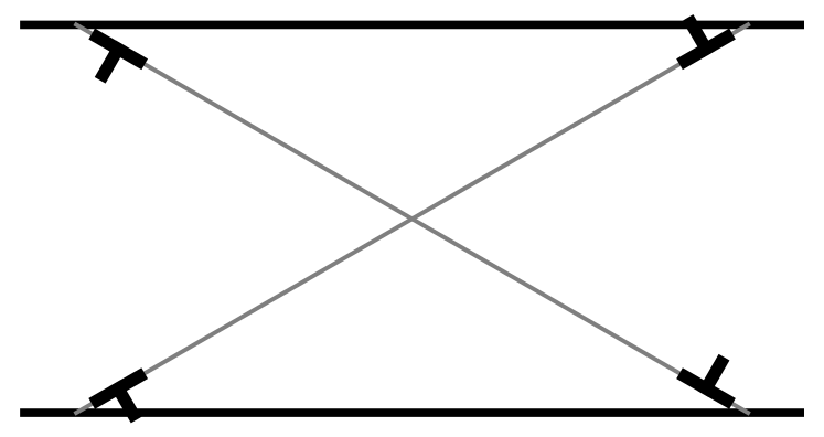
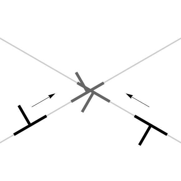
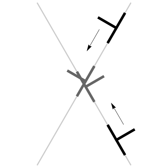
Discrete dislocation dynamics simulations, however, reveal essentially no boundary layers at all—or, equivalently, boundary layers that span the entire width (Fig. 10(a)). Upon closer examination, we find ‘locks’ of dislocations222The use of the phrase ‘locks’ for parallel edge dislocations is somewhat inappropriate, because such dislocations only interact through their long-range field but do not alter the topology as happens in, e.g., Lomer locks. We nevertheless use the term here because it expresses the small-scale interactions that obstruct dislocation motion. of like charges on different slip systems which prevent their motion pile-ups to the boundaries. A pair of dislocations with the relative angle of their Burgers vectors between and feel their mutual attraction when they glide past each other. Although rather weak, this interaction is apparently strong enough in this case for locking to occur. Figs. 11(a) and (b) show the types of dislocations which accumulate at the boundaries for and , respectively. Figs. 11(c) and (d) demonstrate one of the two situations when locking happens in each case (the others are rotations of these). In the region sufficiently far away from the boundaries, event 11(c) is roughly as likely to occur as event 11(d), since the situations differ just by a rotation followed by a flip about the -axis. The relative likelihood, however, increases immensely close to the boundaries because only in the case do dislocations moving to the same boundary permit locking, Fig. 11(c). This mutual locking of slip systems prevents dislocations to reach the boundaries and form localized boundary layers. The locking mechanism is purely a discrete phenomena and cannot be captured by the current continuum theory without further refinement. Due to its relatively small probability, locking seldom occurs in the case.
5 Discussion and Conclusion
We applied the recently formulated multislip continuum plasticity theory to analyze two boundary value problems relating to thin films. In Sec. 3, we studied stress relaxation mechanism in thin films on substrates with thermal loading. We obtained an explicit analytical expression of the stress distribution as a function of slip orientation with one fitting parameter. The predictions were in good agreement with the discrete dislocation results of Nicola et al. (2003, 2005b). Our theory was able to show size-dependent hardening and the hardening due to slip orientations—both of which the previous continuum theory failed to explain. Subsequently, we analyzed simple shear in constrained films. Similarly to the first problem, we observed dislocation pile-ups at the top and bottom constrained boundaries. The thickness of dislocation layers depends weakly on the incremental shear. Regardless of the difference between the forms of slip-interaction coupling between our theory and that in Yefimov and Van der Giessen (2005a), our theory also gave satisfactory agreements with results from discrete dislocation dynamics simulations (Shu et al., 2001). We pointed out that this term can be absorbed into fitting parameter; the correct functional form of the coupling, therefore, cannot be decided only on the basis of this problem.
Acknowledgments
We acknowledge funding from the European Commissions Human Potential Programme SizeDepEn— under contract number MRTN-CT-2003-504634.
References
- Acharya and Bassani (2000) Acharya, A., Bassani, J. L., 2000. Incompatibility and crystal plasticity. J. Mech. Phys. Solids 48, 1565–95.
- Acharya and Beaudoin (2000) Acharya, A., Beaudoin, A. J., 2000. Grain-size effect in viscoplastic polycrystals at moderate strains. J. Mech. Phys. Solids 48, 2213–30.
- Acharya and Roy (2006) Acharya, A., Roy, A., 2006. Size effects and idealized dislocation microstructure at small scales: Predictions of a phenomenological model of mesoscopic field dislocation mechanics: Part i. J. Mech. Phys. Solids 54, 1687–710.
- Aifantis (1984) Aifantis, E. C., 1984. Towards a continuum approach to dislocation patterning. In: Markenscoff, X. (Ed.), Dislocations in Solids—Recent Advances, AMD-63. ASME, pp. 23–33.
- Arsenlis and Parks (2002) Arsenlis, A., Parks, D. M., 2002. Modeling the evolution of crystallographic dislocation density in crystal plasticity. J. Mech. Phys. Solids 50, 1979–2009.
- Arsenlis et al. (2004) Arsenlis, A., Parks, D. M., Becker, R., Bulatov, V. V., 2004. On the evolution of crystallographic dislocation density in non-homogeneously deforming crystals. J. Mech. Phys. Solids 52, 1213–46.
- Arzt (1998) Arzt, E., 1998. Size effects in materials due to microstructural and dimensional constraints: a comparative review. Acta Mater. 16, 5611–26.
- Bassini et al. (2001) Bassini, J. L., Needleman, A., Van der Giessen, E., 2001. Plastic flow in a composite: a comparison of nonlocal continuum and discrete dislocation predictions. Int. J. Solids Struct. 38, 833–53.
- Bittencourt et al. (2003) Bittencourt, E., Needleman, A., Gurtin, M. E., Van der Giessen, E., 2003. A comparison of nonlocal continuum and discrete dislocation plasticity predictions. J. Mech. Phys. Solids 51, 281–310.
- Brown and Ham (1971) Brown, L. M., Ham, R. K., 1971. Dislocation-particle interactions. In: Kelly, A., Nicholson, R. B. (Eds.), Strengthening Methods in Crystals. Elsevier, pp. 12–135.
- Ebeling and Ashby (1966) Ebeling, R., Ashby, M. F., 1966. Dispersion hardening of copper single crystals. Philos. Mag. 13, 805–34.
- El-Azab (2000) El-Azab, A., 2000. Statistical mechanics treatment of the evolution of dislocation distributions in single crystals. Phys. Rev. B 61 (18), 11956.
- Fleck and Hutchinson (1993) Fleck, N. A., Hutchinson, J. W., 1993. A phenomenological theory for strain gradient effects in plasticity. J. Mech. Phys. Solids 41, 1825–57.
- Fleck et al. (1994) Fleck, N. A., Muller, G. M., Ashby, F., Hutchinson, J. W., 1994. Strain gradient plasticity: theory and experiment. Acta Metall. Mater. 42, 475–87.
- Groma (1997) Groma, I., 1997. Link between the microscopic and mesoscopic length-scale description of the collective behavior of dislocations. Phys. Rev. B 56 (10), 5807–13.
- Groma et al. (2003) Groma, I., Csikor, F. F., Zaiser, M., 2003. Spatial correlations and higher-order gradient terms in a continuum description of dislocation dynamics. Acta Materialia 51, 1271–81.
- Groma et al. (2006) Groma, I., Györgyi, G., Kocsis, B., 2006. Debye screening of dislocations. Phys. Rev. Lett. 96, 165503.
- Gurtin (2000) Gurtin, M. E., 2000. On the plasticity of single crystals: free energy, microforces, plastic-strain gradients. J. Mech. Phys. Solids 48, 898–1036.
- Gurtin (2002) Gurtin, M. E., 2002. A gradient theory of single-crystal viscoplasticity that accounts for geometrically necessary dislocations. J. Mech. Phys. Solids 50, 5–32.
- Gurtin (2003) Gurtin, M. E., 2003. On a framework for small-deformation viscoplasticity: free energy, microforces, strain gradients. Int. J. Plast. 19, 47–90.
- Limkumnerd and Sethna (2006) Limkumnerd, S., Sethna, J. P., 2006. Mesoscale theory of grains and cells: crystal plasticity and coarsening. Phys. Rev. Lett. 96, 095503.
- Limkumnerd and Van der Giessen (2007) Limkumnerd, S., Van der Giessen, E., 2007. Statistical approach to dislocation dynamics: From dislocation correlations to formulation of multiple-slip continuum plasticity theory. http://arxiv.org/abs/0710.5045 [cond-mat,stat-mech].
- Ma and Clarke (1995) Ma, Q., Clarke, D. R., 1995. Size dependent hardness of silver single crystals. J. Mater. Res. 10, 853–63.
- Nicola et al. (2005a) Nicola, L., Van der Giessen, E., Gurtin, M. E., 2005a. Effect of defect energy on strain-gradient predictions of confined single-crystal plasticity. J. Mech. Phys. Solids 53, 1280–94.
- Nicola et al. (2003) Nicola, L., Van der Giessen, E., Needleman, A., 2003. Discrete dislocation analysis of size effects in thin films. J. of Appl. Phys. 93, 5920–8.
- Nicola et al. (2005b) Nicola, L., Van der Giessen, E., Needleman, A., 2005b. Two hardening mechanisms in single crystal thin films studied by discrete dislocation plasticity. Phil. Mag. 85, 1507–18.
- Nye (1953) Nye, J. F., 1953. Some geometrical relations in dislocated crystals. Act. Metall. 1, 153–62.
- Ortiz and Repetto (1999) Ortiz, M., Repetto, E. A., 1999. Nonconvex energy minimization and dislocation structures in ductile single crystals. J. Mech. Phys. Solids 47, 397–462.
- Ortiz et al. (2000) Ortiz, M., Repetto, E. A., Stainier, L., 2000. A theory of subgrain dislocation structures. J. Mech. Phys. Solids 48, 2077–114.
- Roy and Acharya (2006) Roy, A., Acharya, A., 2006. Size effects and idealized dislocation microstructure at small scales: Predictions of a phenomenological model of mesoscopic field dislocation mechanics: Part ii. J. Mech. Phys. Solids 54, 1711–43.
- Shu et al. (2001) Shu, J. Y., Fleck, N. A., Van der Giessen, E., Needleman, A., 2001. Boundary layers in constrained plastic flow: Comparison of nonlocal and discrete dislocation plasticity. J. Mech. Phys. Solids 49, 1361–95.
- Stölken and Evan (1998) Stölken, J. S., Evan, A. G., 1998. A microbend test method for measuring the plasticity length scale. Acta Mater. 46, 5109–15.
- Walgraef and Aifantis (1985) Walgraef, D., Aifantis, E. C., 1985. On the formation and stability of dislocation patterns -i, -ii, -iii. Int. J. Eng. Sci. 23, 1351–72.
- Yefimov et al. (2004a) Yefimov, S., Groma, I., Van der Giessen, E., 2004a. Bending of a single crystal: discrete dislocation and nonlocal crystal plasticity simulations. Modelling Simul. Mater. Sci. Eng. 12, 1069–86.
- Yefimov et al. (2004b) Yefimov, S., Groma, I., Van der Giessen, E., 2004b. A comparison of a statistical-mechanics based plasticity model with discrete dislocation plasticity simulations. J. Mech. Phys. Solids 52, 279–300.
- Yefimov and Van der Giessen (2005a) Yefimov, S., Van der Giessen, E., 2005a. Multiple slip in a strain-gradient plasticity model motivated by a statistical-mechanics description of dislocations. Int. J. Solids Struct. 42, 3375–94.
- Yefimov and Van der Giessen (2005b) Yefimov, S., Van der Giessen, E., 2005b. Size effects in single crystal thin films: nonlocal crystal plasticity simulations. Eur. J. Mech. A–Solid 24, 183–93.
- Zaiser et al. (2001) Zaiser, M., Miguel, M. C., Groma, I., 2001. Statistical dynamics of dislocation systems: the influence of dislocation-dislocation correlations. Phys. Rev. B 64, 224102.