Characteristic molecular properties of one-electron double quantum rings under magnetic fields
Abstract
The molecular states of conduction electrons in laterally coupled quantum rings are investigated theoretically. The states are shown to have a distinct magnetic field dependence, which gives rise to periodic fluctuations of the tunnel splitting and ring angular momentum in the vicinity of the ground state crossings. The origin of these effects can be traced back to the Aharonov-Bohm oscillations of the energy levels, along with the quantum mechanical tunneling between the rings. We propose a setup using double quantum rings which shows that Aharonov-Bohm effects can be observed even if the net magnetic flux trapped by the carriers is zero.
pacs:
73.21.-b,75.75.+a,73.22.Dj,73.23.Ra1 Introduction
When the energy levels of two tunnel-coupled semiconductor quantum dots are set into resonance, the carriers localized in the individual nanostructures hybridize forming molecular-like states, in good analogy with atomic molecular bonds[1, 2, 3, 4, 5, 6]. The possibility to engineer the properties of these ’artificial molecules’, such as the bond length, the material and shape of the constituent ’atoms’ or the number and nature of delocalized carriers has opened new paths to learn basic physics of molecular systems[7, 8, 9].
Vertically-coupled[5, 6, 7, 8] and laterally-coupled[10, 11, 12, 13, 14, 15, 16] double quantum dots (DQDs) have received particular attention owing to additional technological implications for the development of scalable two-qubit logic gates[17]. Much less is known about other kinds of artificial molecules, such as double quantum rings (DQRs). This is nonetheless an interesting problem, as the remarkable magnetic properties of semiconductor quantum rings (QRs)[18], related to the Aharonov-Bohm (AB) effect[19], have been thoroughly studied at a single-ring level[20], but their effects at a molecular level remain largely unexplored.
Molecular states in vertically coupled QRs have been investigated[21, 22, 23, 24, 25, 26, 27], but the hybridized orbitals in such systems are aligned along the vertical direction. As a result, their response to vertical magnetic fields, which are responsible for AB effects, is very weak[23]. The electronic states of concentrically coupled QRs have also been studied[28, 29, 30, 31, 32, 33]. However, the markedly different vertical confinement of the inner and outer rings leads to carrier localization in individual rings, preventing molecular hybridization[28, 29, 30, 33].
Recently, we studied the molecular dissociation of yet another kind of structure, namely laterally-coupled QRs.[34] Interestingly, in such structures the two rings may have similar dimensions, which grants the formation of covalent molecular orbitals. In addition, tunnel-coupling takes place in the plane of the rings, thus rendering molecular orbitals sensitive to vertical magnetic fields. These two ingredients make laterally-coupled QRs ideal systems to attain magnetic modulation of molecular bonds and their derived properties. This is the subject of research in the present paper. We investigate the energy structure of DQRs under magnetic fields, and find that the AB-induced ground state crossings lead to sudden maxima of the tunnel splitting between bonding and antibonding orbitals of DQRs, as well as to periodic suppressions of the carrier rotation within the rings.
Laterally-coupled DQRs also offer the possibility to extend the research of AB effects, typically restricted to effectively isolated ring structures (see e.g. Refs. [35, 36, 37, 38]), to composite systems, which may unveil subtleties of these purely quantum mechanical phenomena. As a matter of fact, here we show that, unlike in single QRs[19, 20], AB effects in composite systems need no finite net magnetic flux to take place.
The paper is organized as follows. In Section 2 we describe the theoretical model employed and give details of the DQR structure under consideration. In Section 3 results are reported: in Section 3.1, the energy structure and tunnel splitting of DQRs are studied; in Section 3.2, the expectation value of the rings angular momentum is used as an estimate of the carrier rotation within the rings; finally, in Section 3.3 the AB oscillations of electrons in single and DQRs are compared. Conclusions are presented in Section 4.
2 Physical system and theoretical model
We consider QRs in the Coulomb-blockade regime, charged with only one conduction electron. QRs in this regime may be fabricated using either self-assembly[18] or litographic[35] techniques. However, control of the nanostructure dimensions and positioning is only accurate when using litographic methods. Therefore, for illustration purposes in this work we choose to simulate a DQR system built from etched QRs, as those of Ref. [35].
Since QRs have much stronger vertical than lateral confinement, we calculate the low-lying states of the DQRs using a two-dimensional effective mass-envelope function approximation Hamiltonian which describes the in-plane () motion of the electron in the ring. In atomic units, the Hamiltonian may be written as:
| (1) |
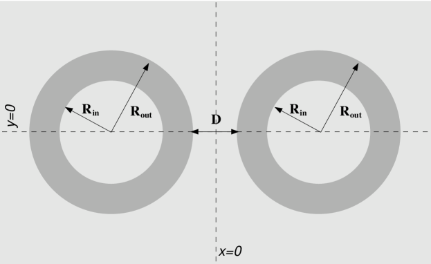
where stands for the electron effective mass, is the canonical moment, and is a square-well potential confining the electron within the DQR structure shown in Fig. 1. In polar coordinates it has the compact expression if and elsewhere, with as the barrier confining potential. is the vector potential. Unless otherwise stated, we use the symmetric gauge, , which introduces a magnetic field pointing along the growth direction . Replacing this vector potential into the Hamiltonian, one obtains:
| (2) |
where . The eigenvalue equation of Hamiltonian (2) is solved numerically using a finite-difference scheme on a two-dimensional grid () extended far beyond the DQR limits.
Following Ref. [35], the QRs we study are made of In0.1Ga0.9As and they are surrounded by GaAs barriers. Reasonable material parameters for this heterostructure are barrier confinement potential meV[35] and effective mass [39]. Unless otherwise stated, the inner radius of the rings is nm, the outer one nm, and the two rings are separated horizontally by a nm barrier.
3 Results
3.1 Energy structure and tunnel splitting
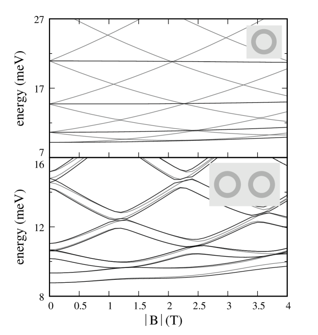
In this section we analyze the energy structure and tunnel-coupling of a DQR under magnetic fields, and compare them to the well-known case of DQDs. The DQD has interdot barrier nm and nm, which gives a similar area to that of the DQR. The energy structure of both kinds of artificial molecule are illustrated in the top panels of Fig. 2.
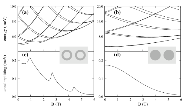
As is known, the DQD energy structure resembles the spectrum of a quantum disk, but with two-fold levels corresponding to the bonding and antibonding linear combinations of the single dot states[10, 11]. In a similar fashion, the DQR energy structure resembles that of a single QR, with the usual AB oscillations, but the levels are two-fold as corresponding to the bonding and antibonding molecular states[34].
The energy spacing between bonding and antibonding energy levels, the so-called tunnel splitting, indicates the strength of the molecular bonds, and it has important practical implications for DQD devices, where it determines the degree of quantum entanglement[6] and affects electron transport[40]. In the bottom row of Fig. 2 we compare the ground state tunnel splitting of the DQD and DQR.
For the DQD, the tunnel splitting decreases monotonically with increasing field, in agreement with experimental data[41] and previous theoretical works[10]. This is because a higher field implies smaller Landau orbits, i.e. the field squeezes the electron wavefunction within the dots, thus reducing the amount of charge in the inter-ring barrier. For DQRs, however, the tunnel splitting no longer exhibits a monotonic behaviour. In general, it also decreases with growing field, due to wavefunction squeezing, but in addition it shows sudden peaks at quasi-periodic values of . Clearly, the values of the field where such peaks occur correspond to the level crossings in the energy structure (Fig. 1(a)), i.e. to integer number of AB periods[19]. This tunneling enhancement, whose origin we explain below, suggests that DQRs enable a stronger magnetic field-induced modulation of the molecular strength than DQDs, and larger tunnel splittings may be achieved when operating at finite magnetic fields, which may be of interest for spin qubit systems, where magnetic fields are used to manipulate spin states[13, 14, 15, 17]. We point out that this behaviour is characteristic for laterally coupled DQRs. In vertically coupled QRs, tunnel splitting is constant against the field[23, 24].
To understand the large values of the DQR tunnel splitting in the vicinity of level crossings, in Fig. 3 (right panel) we zoom in on the lowest-energy levels around the first crossing point. At this point, in a single QR one would expect a series of level crossings[20]. However, Fig. 3 reveals a crossing between the second and third levels only, the first and fourth states being pushed away by apparent anticrossings. This is because the point group symmetry of a QR under vertical magnetic fields, , is lowered to in a DQR. The DQR electron states are then classified by the irreducible representations A and B, indicating even and odd symmetry under a rotation of degrees, respectively.
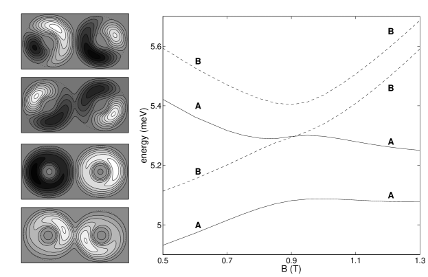
The symmetry of each level can be ellucidated by inspecting the wavefunctions before the anticrossing (left side of Fig. 3). The energy increases from bottom (ground state) to top (fourth state). Only the real part of the wavefunction is illustrated, as it suffices to capture the relevant aspects of the symmetry. It is clear that the first and second (third and fourth) levels form bonding and antibonding molecular states built from the same ’atomic’ orbitals. On the other hand, it can be seen that the first and third levels have symmetry A (even) while the second and fourth ones have symmetry B (odd). Therefore, the symmetry sequence of the four lowest-lying levels shown in Fig. 3 is A B A B before the anticrossing, and A A B B after it.
Since the second and third states have different symmetry, they simply cross each other. By contrast, the first and third (second and fourth) states have the same symmetry, so that they undergo anticrossings. The anticrossings prevent a smooth magnetic field dependece of the tunnel splitting. Hence the non-monotonic evolution of Fig. 2(b).
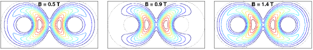
Insight into the tunnel-coupling strenght can be obtained by observing Fig. 4, where we plot the charge density of the ground state before, during and after the anticrossing. At the anticrossing point, where the interaction between the first and third levels is at its maximum, the charge is pushed towards the inter-ring barrier, leading to the tunnel-coupling enhancement reported in Fig. 2(b).
3.2 Expectation value of angular momentum
An intrinsic property of QRs, closely related to the AB effect, is the appearance of one-electron ground states with finite angular momenta, which give rise to an equilibrium current arising from carrier rotation within the structure[20]. In isolated QRs, this current is proportional to the ground state azimuthal angular momentum . In DQRs, due to the lowered symmetry, the angular momentum is no longer a good quantum number. However, the expectation value of the angular momenta within each of the constituent rings can still be taken as a measurement of the carrier rotation within the nanostructure. Thus, in Fig. 5 we compare for a single QR, a DQR with high ( meV) inter-ring barrier and a DQR with regular (experimental-like) barrier height.111For the DQR structures, the is calculated as the sum of the left and right QR local angular momenta, i.e. the expectation values defined from the origin of each QR.
In the single QR case, Fig. 5(a), is a step function, decreasing in one unit of angular momentum with every ground state crossing[20]. A similar behaviour is found in the DQR case with high inter-ring barrier, solid line in Fig. 5(b), as the QRs are almost isolated. However, a new feature appears in the vicinity of the level crossings ( and T). Here, rapidly goes to zero, which implies as a sudden quenching of the carrier rotation. The introduction of full tunnel-coupling in the DQR, solid line in Fig. 5(c), further modifies the magnetic field dependence of . First, no longer takes integer values. Instead, it takes fractional values, reduced as compared to the case of weakly-coupled rings. This is because the charge density in the tunnel barrier, which is now increased, does not contribute to the rotation within the rings. Second, goes to zero every time an AB period is completed, in such a way that the periodic quenching of the ring current starts from weak magnetic fields.
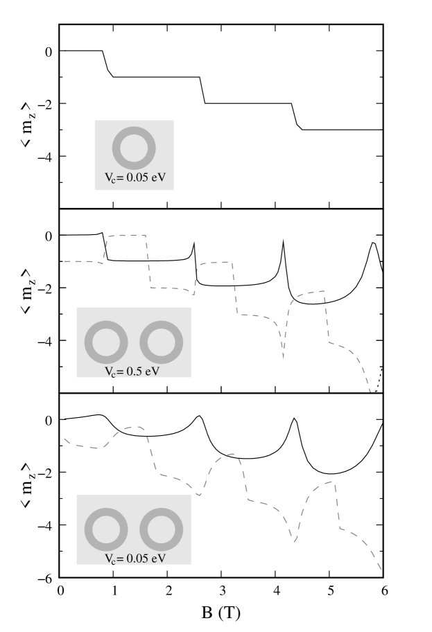
The origin of the peaks in Fig. 5(b) and (c)
is the interaction between the first and third levels of the DQR at the
anticrossing points, discussed above.
Away from the anticrossing, the first and third levels have angular momenta
and , solid and dashed lines in
Fig. 5.
Since these levels are the two lowest bonding orbitals, their angular momenta
are similar to those of the two lowest levels in a single QR.
At the anticrossing, however, the strong interaction couples
and in such a way that the
ground state tends to
and the excited state to
.
Thus, at the first anticrossing ,
at the second one ,
at the third one , etc.
By contrast, the ground state does not reach the expected value, because it tends to deposit a large amount of
charge density in the tunneling barrier (recall Fig. 4 center).
This provides maximum stabilization for the (bonding) ground state,
but it also leads to .
In typical QR structures, the physical observable is the persistent current[42], which is proportional to the magnetization[43]:
| (3) |
Here is the ground state energy. The persistent current includes not only the current arising from the electron angular momentum, but also that coming from the interaction with the magnetic field vector potential[44]. Thus, rather than presenting complete suppressions, the persistent current looks as in Fig. 6, where the magnetization is represented. While in single QRs the magnetization would give a saw-tooth picture[43, 45, 46], here rounded edges are obtained. This is a usual signature of lowered symmetry, which allows additional interactions among the states[47]. The interactions are particularly strong at the crossing points, thus producing the rounded edges.

3.3 AB oscillations in DQRs with zero net magnetic flux
The energy level oscillations of charged carriers confined in QRs under magnetic fields, as those shown in Fig. 2(a), constitute a manifestation of the AB effect, i.e. an action upon the quantum system exerted by the vector potential [19]. The action is induced by the magnetic flux enclosed in the trajectory described by the carrier, . Every time this flux is a multiple of the unit flux quantum, , the energy spectrum retrieves the zero field structure[48] and the system is said to accumulate one AB phase unit[20]. Experimental evidence of such AB oscillations have been reported in different types of mesoscopic[37] and nanoscopic semiconductor QRs.[35, 36].
In this section, we report on the (to our knowledge) first study of AB effect in composite systems, and reveal a new aspect of this phenomenon, namely that AB oscillations can be found even when the total flux trapped by the carriers is , provided the flux threading the individual rings is finite. To this end, we consider two magnetic field configurations:
-
1.
a uniform positive magnetic field goes through the entire system. Hereafter we refer to this as parallel field, .
-
2.
a local positive field goes through the right side of the structure, while a negative one goes through the left one. Hereafter we refer to this as antiparallel field, .
The two cases can be modeled using a Coulomb gauge vector potential for the right side of the plane, and for the left one, where the positive (negative) sign applies for parallel (antiparallel) fields. Note that this gauge choice grants continuity of and in the whole domain The Hamiltonian now reads:
| (4) |
where the negative sign of the linear term in applies for and .
We diagonalize Eq. (4) to calculate the energy structure of a single QR and that of a DQR under parallel and antiparallel magnetic fields. The results, corresponding to rings with nm and nm ( nm for the DQR), are shown in Fig. 7. For a single QR, while (gray lines) yields usual AB oscillations, (black lines) yields a featureless spectrum, affected by the diamagnetic shift only. This is the expected difference between the cases where finite and null magnetic flux is trapped by the carrier.
A strikingly different response is however obtained for the DQR, as the energy structure looks almost the same regardless of the magnetic field configuration. This is surprising, because in the antiparallel case, the magnetic flux penetrating the left and right rings cancels out, so that the net flux enclosed by the electron is again zero, and one may not expect AB manifestations.
To gain some insight into the different behavior of the single and double QR, in Fig. 8 we depict the angular momentum expectation value for the left () and right () halves of the each structure, as a function of . Clearly, the antiparallel field induces opposite left and right angular momenta for both structures. Therefore, , which is consistent with the systems picking a net zero AB phase[20]. Yet, only the single QR energy spectrum shows no AB oscillations.
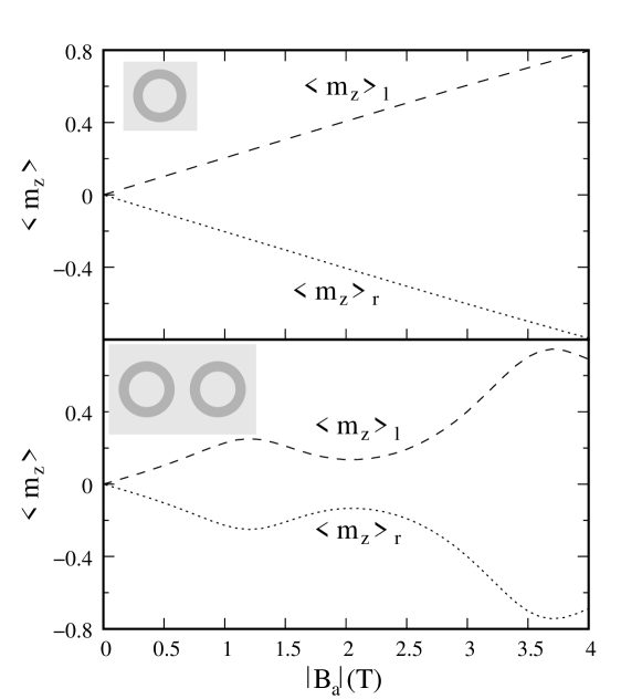
This can be interpreted as follows. The antiparallel field induces clockwise and anticlockwise carrier rotation in each half of the structure. For a single QR, the two currents cancel each other out, the angular momentum of the ring is always zero and then the states are insensitive to the linear term of the magnetic field (responsible for the AB effects). By contrast, for a DQR, the are finite (though opposite) currents in each of the rings. Thus, if the left and right rings were uncoupled, it is immediate that both would trap magnetic flux and hence show AB oscillations. Moreover, from the symmetry of Hamiltonian (4), it is easy to show that the energy spectrum of the two uncoupled QRs would be identical but with reversed sign of the angular momenta (in other words, the currents are identical in magnitude but opposite in sign).
Switching on the tunnel-coupling enables the electron to delocalize over the two rings while keeping the net trapped magnetic flux zero. Still, as can be seen in the bottom panel of Fig. 7, the spectra under parallel or antiparallel fields remain similar. This is because the tunnel-coupling for the two magnetic field configurations is qualitatively similar (although not identical) as can be seen in Fig. 9, where gray lines represent the tunnel splitting under and black lines that under . Note also that, in the antiparallel field case, the tunnel splitting increases with , this being responsible for the differences in the energy spectra of Fig. 7. The same behaviour is found in DQRs with stronger tunnel-coupling, as shown in Fig. 9 inset, where the tunnel splitting of DQRs with a thin ( nm) barrier is plotted.
We then conclude that both the individual ring energies and the tunnel-coupling are similar for and , which explains the appearence of similar spectra in Fig. 7.
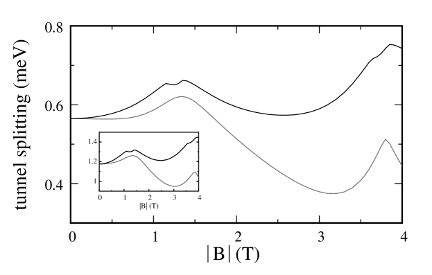
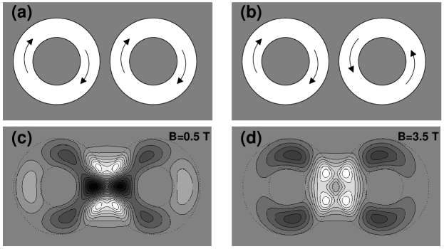
Last, we comment on the fact that the tunnel splitting increases with in the DQR subject to antiparallel field, Fig. 9. This is an anomalous behaviour, because the increasing magnetic confinement should lead to reduced charge density in the barrier and hence to decreasing tunnel splitting, as in the parallel field case[41]. This can be explained in terms of the sense of the carrier circulation in each ring. For parallel field, the electron rotates in the same sense (say clockwise) in the two rings. As a result, the current in the surroundings of the tunneling barrier is different for each ring (see schematic representation in Fig. 10(a)). This hinders the charge sharing between the subsystems. By contrast, for antiparallel field, the sense of rotation in the left and right rings is opposite. As a result, the current in the surroundings of the tunneling barrier is now the same (Fig. 10(b)). This in turn favours the charge density sharing. With increasing field, the current grows and these trends become more important[49]. Indeed, for antiparallel field, the favoured charge sharing is able to compensate for the wavefunction squeezing.
To illustrate this effect, in Fig. 10(c) and (d) we plot the difference in charge density between and ground states, for weak ( T) and strong ( T) magnetic fields. White contour regions indicate excess charge density coming from the antiparallel case, and black regions vice-versa. When the field is weak, the charge density in the barrier is similar for the two systems. However, for the strong field, it is apparent that the antiparallel ground state deposits much more density in the tunneling barrier, which results in its enhanced tunnel-coupling.
4 Conclusions
We have shown that the electron states in side-coupled coupled QRs display a characteristic behaviour when subject to vertical magnetic fields, different from that observed in other QR and QD structures. In particular, the tunnel-coupling strength is found to oscillate with the field, showing sharp maxima when the AB effect induces ground state crossings. This may be of interest e.g. for strong magnetic modulation of the transport probability between the nanostructures. In these tunnel-coupling maxima, the carrier rotation within the rings is abruptly supressed, owing to charge accumulation in the inter-ring barrier. This introduces a characteristic magnetic field dependence of the persistent currents which may be verified experimentally.[42]
We have also shown that DQRs, as quadruply-connected systems, may reveal new fundamental aspects of quantum physics arising from the AB effect. In the single QR structures (doubly-connected systems) investigated to date, a non-zero magnetic flux piercing the loop is required to produce AB effects, such as AB oscillations. From our theoretical prediction, it follows that this is not necessarily the case for DQRs, where AB oscillations are present even if the net magnetic flux piercing the two loops (and hence the total accumulated AB phase) is zero, provided the flux going through the individual rings is finite. The experimental setup to prove this should consist of two tunnel-coupled QRs subject to antiparallel magnetic fields in the left and right rings. DQR structures can be currently realized with remarkable precision using litographic techniques, as in Refs. [35, 37], but the antiparallel field realization may be more challenging. Laser-controlled currents might provide a feasible alternative[50].
References
References
- [1] Kouwenhoven L, Science 268, 1440 (1995).
- [2] Holleitner AW, Blick RH, Hüttel AK, Eberl K, and Kotthaus JP, Science 297, 70 (2002).
- [3] Alivisatos AP, Johnsson KP, Peng X, Wilson TE, Loweth CJ, Bruchez MP, and Schultz PG, Nature 382, 609 (1996).
- [4] Blick RH, Pfannkuche D, Haug RJ, Klitzing KV, and Eberl K, Phys. Rev. Lett. 80, 4032 (1998).
- [5] Austing DG, Honda T, Muraki K, Tokura Y, and Tarucha S, Physica B 249-251, 206 (1998).
- [6] Bayer M, Hawrylak P, Hinzer K, Fafard S, Korkusinski M, Wasilewski ZR, Stern O, and Forchel A, Science 291, 451 (2001).
- [7] Pi M, Emperador A, Barranco M, Garcias F, Muraki K, Tarucha S, and Austing DG, Phys. Rev. Lett. 87, 066801 (2001).
- [8] Doty MF, Climente JI, Korkusinski M, Scheibner M, Bracker AS, Hawrylak P, and Gammon D, (to be published).
- [9] Dybalski W, and Hawrylak P, Phys. Rev. B 72, 205432 (2005).
- [10] Cha M, and Chung M, J. Korean Phys. Soc. 41, 359 (2002).
- [11] Stano P, and Fabian J, Phys. Rev. B 72, 155410 (2005).
- [12] Abolfath R and Hawrylak P, J. of Chem. Phys. 125, 034707 (2006).
- [13] van der Wiel WG, Stopa M, Kodera T, Hatano T, and Tarucha S, New J. Phys. 8, 28 (2006).
- [14] Petta JR, Johnson AC, Taylor JM, Yacoby A, Lukin MD, Marcus CM, Hanson MP, and Gossard AC, Physica E 34, 42 (2006), and references therein.
- [15] Koppens FHL, Buizert C, Tielrooij KJ, Vink IT, Nowack KC, Meunier T, Kouwenhoven LP, and Vandersypen LMK, Nature 442, 766 (2006).
- [16] van der Wiel WG, De Franceschi S, Elzerman JM, Fujisawa T, Tarucha S, Kouwenhoven LP, Rev. Mod. Phys. 75, 1 (2002).
- [17] Loss D, and DiVicenzo DP, Phys. Rev. A 57 120 (1998).
- [18] Lee BC, Voskoboynikov OP, and Lee CP, Physica E 24, 87 (2004), and references therein.
- [19] Aharonov Y, and Bohm D, Phys. Rev. 115, 485 (1959).
- [20] Viefers S, Koskinen P, Singha Deo P, and Manninen M, Physica E 21 1 (2004), and references therein.
- [21] Suarez F, Granados D, Dotor ML, and Garcia JM, Nanotechnology 15, S126 (2004).
- [22] Granados D, Garcia JM, Ben T, and Molina SI, Appl. Phys. Lett. 86, 071918 (2005).
- [23] Climente JI, and Planelles J, Phys. Rev. B 72, 155322 (2005).
- [24] Li Y, and Lu HM, Jap. J. Appl. Phys. 43, 2104 (2004).
- [25] Malet F, Barranco M, Lipparini E, Mayol R, Pi M, Climente JI, and Planelles J, Phys. Rev. B 73, 245324 (2006).
- [26] Castelano LK, Hai GQ, Partoens B, and Peeters FM, Phys. Rev. B 74, 045313 (2006).
- [27] Piacente G, and Hai GQ, J. Appl. Phys. 101, 124308 (2007).
- [28] Mano T, Kuroda T, Sanguinetti S, Ochiai T, Tateno T, Kim J, Noda T, Kawabe M, Sakoda K, Kido G and Koguchi N, Nanoletters 5, 425 (2005).
- [29] Fuster G, Pacheco M, and Barticevic Z, Braz. J. Phys. 34, 666 (2004).
- [30] Planelles J, and Climente JI, Eur. Phys. J. B 48, 65 (2005).
- [31] Szafran B, and Peeters FM, Phys. Rev. B 72 155316 (2005).
- [32] Climente JI, Planelles J, Barranco M, Malet F, and Pi M, Phys. Rev. B 73, 235327 (2006).
- [33] Malet F, Pi M, Barranco M, Lipparini E, and Serra L., Phys. Rev. B 74, 193309 (2006).
- [34] Planelles J, Rajadell F, Climente JI, Royo M, and Movilla JL, J. Phys. Conf. Ser. 61, 936 (2007).
- [35] Bayer M, Korkusinski M, Hawrylak P, Gutbrod T, Michel M, and Forchel A, Phys. Rev. Lett. 90, 186801 (2003).
- [36] Lorke AL, Luyken RJ, Govorov AO, and Kotthaus JP, Phys. Rev. Lett. 84, 2223 (2000).
- [37] Fuhrer A, Lüscher S, Ihn T, Heinzel T, Ensslin K, Wegscheider W, and Bichler M, Nature 413, 822.
- [38] Chandrasekhar V, Rooks MJ, Wind S, and Prober DE, Phys. Rev. Lett. 55, 1610 (1985).
- [39] Korkusinski M, Hawrylak P, and Bayer M, Phys. Status Solidi B 234, 271 (2002).
- [40] Huttel AK, Ludwig S, Lorenz H, Eberl K, and Kotthaus JP, Phys. Rev. B 72, 081310(R) (2005).
- [41] Huttel AK, Ludwig S, Lorenz H, Eberl K, and Kotthaus JP, Physica E 34, 488 (2006).
- [42] Kleemans NAJM, Boominar-Silkens IMA, Fomin VM, Gladilin VN, Granados D, Taboada AG, Garcia JM, Offermans P, Zeitler U, Christiansen PCM, Maan JC, Devreese JT, and Koenraad PM, Phys. Rev. Lett. 99, 146808 (2007).
- [43] Cheung HF, Gefen Y, Riedel EK, and Shih WH, Phys. Rev. B 37, 6050 (1988).
- [44] In strictly one-dimensional QRs, the persistent current is given by , where is the electron charge, the ring radius, the magnetic flux and the unit of flux.
- [45] Chakraborty T, and Pietiläinen P, Phys. Rev. B 50, 8460 (1994).
- [46] Climente JI, Planelles J, and Movilla JL, Phys. Rev. B 70, 081301(R) (2004).
- [47] Planelles J, Rajadell F, and Climente JI, Nanotechnology 18, 375402 (2007).
- [48] Except for the additional diamagnetic shift.
- [49] In other words, the coupling between left and ring wavefunctions is larger when the localized states have opposite angular momenta (antiparallel field), and smaller when they have the same angular momenta (parallel field). The larger and , the more so.
- [50] Pershin YV, and Piermarocchi C, Phys. Rev. B 72, 245331 (2005).