Method for Full Bloch-Sphere Control of a Localized Spin via a Single Electrical Gate
Abstract
We calculate the dependence on an applied electric field of the g tensor of a single electron in a self-assembled InAs/GaAs quantum dot. We identify dot sizes and shapes for which one in-plane component of the g tensor changes sign for realistic electric fields, and show this should permit full Bloch-sphere control of the electron spin in the quantum dot using only a static magnetic field and a single vertical electric gate.
Manipulating individual spins in solids requires quickly and coherently reorienting localized spins while leaving neighboring spins unaffectedAwschalom et al. (2002). Difficulties confining oscillating magnetic fields have motivated alternate approaches that use electric fields to change the local magnetic environment, including moving an electron within a hyperfine field gradientPetta et al. (2005) or fringe-field gradientTokura et al. (2006). Higher temperatures require spins to be localized in much smaller quantum dots, where these techniques are less effective. In contrast, approaches that couple the spin to an electric field via the spin-orbit interactionKalevich and Korenev (1993); Oestreich et al. (1996); Ivchenko et al. (1997); Jiang and Yablonovitch (2001); Salis et al. (2001); Kato et al. (2003); Doty et al. (2006); Nakaoka et al. (2007), especially via g tensor manipulation techniquesKato et al. (2003), should be scalable to small dots with large confinement. Here we calculate the g tensor of a single electron in a small quantum dot and show the symmetry of its electric field dependence permits full Bloch sphere control of the spin using an electric field applied in a single direction. We find the spin manipulation frequency of an InAs/GaAs QD in 1 Tesla exceeds 150 MHz.
The energy difference between a spin-up and spin-down state (Zeeman energy) of an electron in a zincblende direct-gap semiconductor depends on the band gap and spin-orbit splitting in the materialRoth et al. (1959). The Zeeman energy thus can be modulated in a semiconductor heterostructure, even for a static magnetic field, by changing the overlap of the electronic wave function with different materialsIvchenko et al. (1997); Jiang and Yablonovitch (2001); Salis et al. (2001); Doty et al. (2006). Other contributions in a system of low symmetry, such as a quantum well or quantum dot (QD), produce very different Zeeman energies from the same magnetic field when it is applied along different principal axesIvchenko and Pikus (1997), as described by the Hamiltonian
| (1) |
Here is the electron charge, its mass, S is the electron spin operator, is the Landé g tensor, B is the magnetic field, is Planck’s constant and is the spin precession vector. From Eq. (1), a change in the Zeeman energy in a static magnetic field corresponds to a change in the g tensor. As the g tensor changes due to a changing applied electric field in a semiconductor heterostructure, the spin precession vector changes both its magnitude and direction, permitting reorientation of the spin. An oscillating electric field produces an oscillating transverse , which allows resonant control of the spin orientation in a static magnetic field, as demonstrated in quantum wellsKato et al. (2003). As these manipulations only require electric-field modulation, traditional high-density electric gate design strategies may be applicable to high-density arrays of single-spin devices.
Several significant challenges stand in the way of manipulating single spins using these methods. The strong confinement in QDs leads to a quenching of the orbital motion of the electron, driving the components of the g tensor towards the free-electron value of , and reducing the potential modulation of the g tensor in an electric fieldPryor and Flatté (2006). The long spin coherence times for electrons relative to holesMeier and Zachachrenya (1984); Kroutvar et al. (2004); Petta et al. (2005) favors their use as coherent single-spin entities. However, due to the greater effective confinement of electrons in a quantum dot, the electric-field tunability of the electron g tensor would be much smaller than the corresponding tunability for holes or excitons. Furthermore, to be able to conveniently and rapidly reorient the spin to any direction on the Bloch sphere, the ability to generate precession around two orthogonal axes is highly desirable, which might be expected to involve independent control of two electric fields. Manipulating an electric field along two directions in a nanoscale device would make the high-density integration of single-spin devices considerably more complex. We find that tall dots provide sufficient tuning for 150 MHz spin manipulation, and that full Bloch sphere control is possible with a single vertical gate.
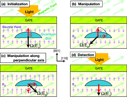
We now consider a single electron in an InAs/GaAs dot in a static magnetic field, with a series of electric fields applied by a top gate which will re-orient the spin in an arbitrary direction (Fig. 1). The growth direction is [001] and the principal axes of the g tensor are [001], [110], and [10]. We will refer to the values of g along these principal axes as the g tensor components. The magnetic field lies in the [001]–[110] plane, for reasons described later. The initial field gives an parallel to the [001] direction (Fig. 1(a)), allowing efficient spin initialization by optical illuminationMeier and Zachachrenya (1984); Pryor and Flatté (2003), and stabilizing the spin polarization until it is time to manipulate the spin. Guaranteeing this orientation of for the magnetic field shown in Fig. 1 requires and (here assumed ). Figs. 1(bc) show the quantum dot’s spin dynamics in response to the electric fields and , which produce spin precession vectors along two perpendicular axes. Fig. 1(d) returns the electric field to . The polarization of the single spin along [001] can now be measured optically, e.g. by Faraday or Kerr rotationLeuenberger et al. (2005); Mikkelsen et al. (2007).
The two perpendicular spin precession vectors shown in Fig. 1(bc) are central to achieving full Bloch sphere control of the spin. The condition that two spin precession vectors are perpendicular, , can be rewritten using Eq. (1) as
| (2) |
for . Equation (2) can only be satisfied if one (and only one) of the tensor components changes sign, which should be to permit the desired configuration in Fig. 1(a). For pointing in an arbitrary direction either one or two components of g must change sign. A change in sign for a component of g has been demonstrated experimentally in quantum wellsSalis et al. (2001), but the observed changes of g in quantum dots have been very smallNakaoka et al. (2007). A change in sign with magnetic field has been predicted theoretically for large quantum dotsDestefani and Ulloa (2005). Here we rely on a change in electric field to change the sign, which is suggested by the height-dependence of the in-plane components of the g tensorPryor and Flatté (2006). This effect was also hinted at by the difference in sign between growth-direction g tensor components calculated for spherical and semispherical CdTe dotsPrado et al. (2004). Thus we find that to achieve full control over a spin with only a single, growth-direction electric field, as shown in Fig. 1(bc), one component of the g tensor must change sign. That component would be preferably along an axis perpendicular to the growth direction.
We now describe our calculated results of g for a broad range of InAs/GaAs quantum dots, and find many dots for which one in-plane component of the tensor changes sign with applied electric field. Our evaluation of the precession frequency of the spin in these dots under the conditions of Fig. 1(bc) yields MHz in a 1 Tesla field. The precession frequency scales with the magnitude of the applied magnetic field, so a reasonable laboratory field can produce a precession frequency in excess of 1 GHz.
We calculate the electron g tensor in the dots using a strain-dependent 8-band modelBahder (1990) solved in real spacePryor (1998) that includes both the orbital and the spin effects of the magnetic field in a lattice gauge theory formulationPryor and Flatté (2006). To calculate a g tensor component along a principal axis ([001], [110], or [10]), a 1 Tesla field is applied along the corresponding axis and the energy splitting between the two lowest-energy spin-dependent conduction states is determined. The sign of each g tensor component was found by computing to determine the spin alignment.
The electric-field dependence of the g tensor components is shown in Fig. 2 for a dot with a geometry favorable for spin manipulation for the magnetic field shown in Fig. 1. The lens-shaped dot has a height of 6.2 nm, with a base elongated along the [110] direction so that the dot diameters in the in-plane directions differ: and . Dot height-to-base aspect ratios and elongations such as this can be achieved by manipulating growth conditions. Even larger height-to-base aspect ratios are possible using pillaring techniquesHe et al. (2007). A key feature of this dot is that for an electric field ( kV/cm) considerably below the breakdown voltage of the host semiconductor ( kV/cm). As the dot shape is not symmetrical along the [001] direction the response to the electric field is not symmetric around , and has a sizable -linear dependence. This effect will occur for all asymmetric dots, including lithographic dots, but to a different degree. All electric fields considered in Fig. 2 are less than half the typical breakdown field of GaAs. The sign of all the g tensor components is negative at . We can select from Fig. 2 the values of the electric field that correspond to the panels in Fig. 1. Fig. 1(a) and (d) correspond to kV/cm, for which and is parallel to . Fig. 1(b) corresponds to kV/cm, for which . Fig. 1(c) corresponds to kV/cm, for which . For a magnetic field rotated slightly (3.4o) from [110] towards the [001] direction, the spin precession axis will point as shown in Fig. 1(bc) for and .
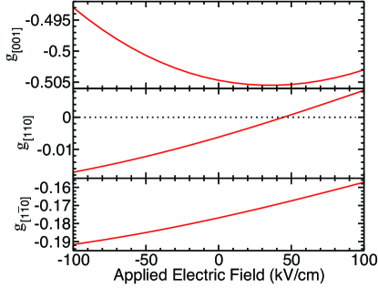
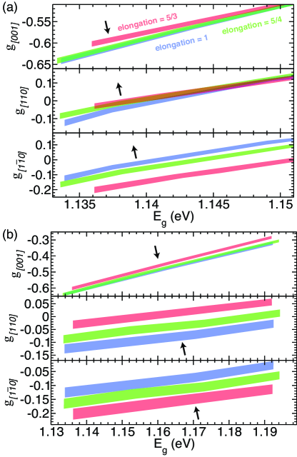
Figure 3 shows the results of a more extensive study as a function of dot shape and size. For the trends in g are similar to those reported earlier for both growth-directionNakaoka et al. (2004); Pryor and Flatté (2006) and in-plane componentsPryor and Flatté (2006). In Fig. 3(a) the dot footprint is fixed and the height is changed. The results are plotted as a function of quantum dot energy gap. Fig. 3(b) shows similar results, but the height is fixed and the footprint is changed. The width of the bands corresponds to the change in g as the electric field is changed from -100kV/cm to 100kV/cm. As shown in Fig. 3(a), for all three elongations () there is a height, corresponding to a quantum dot energy gap of eV, for which will change sign with applied electric field. As shown in Fig. 3(b), however, for fixed height and varying footprint will change sign with applied electric field for dots with gaps that vary by over 50 meV, permitting some tuning of the optical excitation energy of an optimized dot.
In all cases the smaller dots have larger quantum dot energy gaps, due to the increased confinement of both electrons and holes. Increased electron confinement quenches the orbital angular momentum of the electronic wavefunctionPryor and Flatté (2006) and drives the g tensor closer to the free electron value of 2. Thus dots with larger ’s will have g tensors closer to 2, a trend visible in Fig. 3. A positive electric field ( and in Fig. 1) pushes the electronic wave function towards the base of the dot, whereas a negative electric field ( in Fig. 1) pushes it towards the apex. The electric field dependence of the g tensor comes from several effects: confinement-induced angular momentum quenchingPryor and Flatté (2006), changes in the dot energy gap due to the quantum confined Stark effectEmpedocles and Bawendi (1997), and variation in the heavy/light hole spitting from the electron wave function overlapping different parts of the inhomogeneously strained dot. These effects, along with the anisotropy of the dot confining potential, produce anisotropy in the electric field dependence of the g tensor that is even more extreme than the anisotropy in the magnitude of g.
We also find that dots with g tensor components that change sign are well-suited for resonant oscillation of the g tensor (g tensor modulation resonanceKato et al. (2003)). Here the approach would be to use a static electric field and add a harmonically oscillating electric field. We linearize the field dependence of the components of the g tensor,
| (3) |
and the resulting precession axis,
| (4) |
The optimal choice of magnetic field orientation for resonant manipulation corresponds to that field orientation where the component of transverse to is maximized. The Rabi frequency is
| (5) |
To evaluate the Rabi frequency we neglect the dependence of on electric field over the range shown in Fig. 2, as that dependence is much smaller than the relative changes of the in-plane components. We find that the largest Rabi frequencies can be achieved for any in-plane orientation of the magnetic field if the proper polar angle (measured from [001]) for B is chosen. For the dot characterized in Fig. 2, the optimal polar angle ranges from for an in-plane magnetic field parallel to [110] to for an in-plane magnetic field parallel to [10]. The resulting Rabi frequency is approximately 150 MHz for a 1 Tesla magnetic field, essentially the same as the spin precession frequency obtained for the geometry shown in Fig. 1(bc). Thus for a reasonable laboratory magnetic field of 10 Tesla the Rabi frequency would exceed 1 GHz.
Full control of a localized spin using a single growth-direction electric field applied using a nanoscale top gate should provide scalable methods of manipulating single spins in semiconductor quantum dot systems. The ability to set the electric field to make vanish also allows the spin precession vector to be oriented parallel to the growth direction when desired, and permits the convenient storage of optically-excited polarized spins until they are ready for manipulation.
We acknowledge support from an ONR MURI and an NSF NIRT.
References
- Awschalom et al. (2002) D. D. Awschalom, N. Samarth, and D. Loss, eds., Semiconductor Spintronics and Quantum Computation (Springer Verlag, Heidelberg, 2002).
- Petta et al. (2005) J. R. Petta, A. C. Johnson, J. M. Taylor, E. A. Laird, A. Yacoby, M. D. Lukin, C. M. Marcus, M. P. Hanson, and A. C. Gossard, Science 309, 2180 (2005).
- Tokura et al. (2006) Y. Tokura, W. G. van der Wiel, T. Obata, and S. Tarucha, Phys. Rev. Lett. 96, 047202 (2006).
- Kalevich and Korenev (1993) V. K. Kalevich and V. L. Korenev, JETP Lett. 57, 571 (1993).
- Oestreich et al. (1996) M. Oestreich, S. Hallstein, and W. W. Rühle, IEEE J. Quant. Electron. 2, 747 (1996).
- Ivchenko et al. (1997) E. L. Ivchenko, A. A. Kiselev, and M. Willander, Solid State Comm. 102, 375 (1997).
- Jiang and Yablonovitch (2001) H. W. Jiang and E. Yablonovitch, Phys. Rev. B 64, 041307 (2001).
- Salis et al. (2001) G. Salis, Y. Kato, K. Ensslin, D. C. Driscoll, A. C. Gossard, and D. D. Awschalom, Nature 414, 619 (2001).
- Kato et al. (2003) Y. Kato, R. C. Myers, A. C. Gossard, J. Levy, and D. D. Awschalom, Science 299, 1201 (2003).
- Doty et al. (2006) M. F. Doty, M. Scheibner, I. V. Ponomarev, E. A. Stinaff, A. S. Bracker, V. L. Korenev, T. L. Reinecke, and D. Gammon, Phys. Rev. Lett. 97, 197202 (2006).
- Nakaoka et al. (2007) T. Nakaoka, S. Tarucha, and Y. Arakawa, Phys. Rev. B 76, 041301 (2007).
- Roth et al. (1959) L. M. Roth, B. Lax, and S. Zwerdling, Phys. Rev. 114, 90 (1959).
- Ivchenko and Pikus (1997) E. L. Ivchenko and G. E. Pikus, Superlattices and Other Heterostructures (Springer, New York, 1997).
- Pryor and Flatté (2006) C. E. Pryor and M. E. Flatté, Appl. Phys. Lett. 88, 233108 (2006).
- Meier and Zachachrenya (1984) F. Meier and B. P. Zachachrenya, Optical Orientation: Modern Problems in Condensed Matter Science, vol. 8 (North-Holland, Amsterdam, 1984).
- Kroutvar et al. (2004) M. Kroutvar, Y. Ducommun, D. Heiss, M. Bichler, D. Schuh, G. Abstreiter, and J. J. Finley, Nature 432, 81 (2004).
- Pryor and Flatté (2003) C. E. Pryor and M. E. Flatté, Phys. Rev. Lett. 91, 257901 (2003).
- Leuenberger et al. (2005) M. N. Leuenberger, M. E. Flatté, and D. D. Awschalom, Phys. Rev. Lett. 94, 107401 (2005).
- Mikkelsen et al. (2007) M. H. Mikkelsen, J. Berezovsky, N. G. Stoltz, L. A. Coldren, and D. D. Awschalom, Nature Physics 3, 770 (2007).
- Destefani and Ulloa (2005) C. F. Destefani and S. E. Ulloa, Phys. Rev. B 71, 161303 (2005).
- Prado et al. (2004) S. J. Prado, C. Trallero-Giner, A. M. Alcalde, V. López-Richard, and G. E. Marques, Phys. Rev. B 69, 201310R (2004).
- Bahder (1990) T. B. Bahder, Phys. Rev. B 41, 11992 (1990).
- Pryor (1998) C. Pryor, Phys. Rev. B 57, 7190 (1998).
- He et al. (2007) J. He, H. Krenner, C. Pryor, J. P. Zhang, Y. Wu, D. Allen, C. Morris, M. Sherwin, and P. M. Petroff, Nano Letters 7, 802 (2007).
- Nakaoka et al. (2004) T. Nakaoka, T. Saito, J. Tatebayashi, and Y. Arakawa, Phys. Rev. B 70, 235337 (2004).
- Empedocles and Bawendi (1997) S. A. Empedocles and M. G. Bawendi, Science 278, 2114 (1997).