Spatial and temporal characterization of a Bessel beam produced using a conical mirror
Abstract
We experimentally analyze a Bessel beam produced with a conical mirror, paying particular attention to its superluminal and diffraction-free properties. We spatially characterized the beam in the radial and on-axis dimensions, and verified that the central peak does not spread over a propagation distance of . In addition, we measured the superluminal phase and group velocities of the beam in free space. Both spatial and temporal measurements show good agreement with the theoretical predictions.
pacs:
42.25.BsI Introduction
A special class of non-diffracting light waves called Bessel beams Durnin4 have been extensivelly studied over the last two decades. Bessel beams are characterized by a transverse field profile in the form of a zero-order Bessel function of the first kind. They exhibit several intriguing properties, such as diffraction-free propagation of the central peak over a distance fixed only by the geometry of the source device, and superluminal phase and group velocities in free space. Due to their diffraction-free characteristics, they have found applications in several fields of physics. Non-diffractive pump fields have been utilized in nonlinear optical processes like parametric down conversion BelviKazak ; Belyi ; Orloy ; Trapani ; Longhi ; Piskarskas , second Wulle ; Arlt ; Ding ; Jedrkiewicz , third Peet , and higher-order harmonic generation Averchi . Furthermore, the accuracy of optical tweezers Milne ; Garces ; Summers , optical trapping Arlt63 ; Garces66 ; Fan ; Tatarkova ; Arakelyan and the resolution of medical imaging Rolland ; Jianyu have been enhanced by the implementation of diffraction-free beams.
In addition to exploiting the non-diffractive feature of Bessel beams, superluminality has also been a subject of investigation. There have been attempts to demonstrate this property using light in the microwave range Mugnai but the experimental uncertainties induced by the apparatus were large compared to the magnitude of the superluminal effect Ringermacher ; Bigelow . Recently, the propagation velocity of an ionization wavefront induced by a Bessel pulse has also been measured Alexeev , but until now no measurement revealed both superluminal group and phase velocities in free space.
Here, we report a complete characterization of spatio-temporal properties of an optical Bessel beam generated by reflection from a conical mirror Fortin . This novel technique of producing Bessel beams has the advantage, with respect to commonly used axicons Mcleod , of avoiding dispersion and is thus more suited for applications that require ultrashort laser pulses.
In the following we describe the spatially characterization of the beam, showing non-diffractive properties over its propagation range. Later we show a set of measurements of superluminal phase and group velocities in free space that has greater accuracy than ever previously measured.
II Beam Properties
A non-diffractive Bessel beam is realized by a coherent superposition of equal-amplitude, equal-phase plane waves whose wavevectors form a constant angle , called the axicon angle, with the direction of propagation of the beam which we define as the -axis.
As originally proposed by Durnin Durnin4 , the analytical solution of the Helmholtz equation for the electric field propagation is given by:
| (1) |
where is constant, , , is the wave-vector, is the angular frequency, is the radial coordinate and is a zeroth-order Bessel function of the first kind. Equation (1) defines a non-diffracting beam since the intensity distribution is independent of and equal to . Furthermore, the field described in Eq. (1) propagates with a superluminal phase velocity given by . The independence of the phase velocity from the field frequency implies that in free space the group velocity is also superluminal and is equal to the phase velocity.
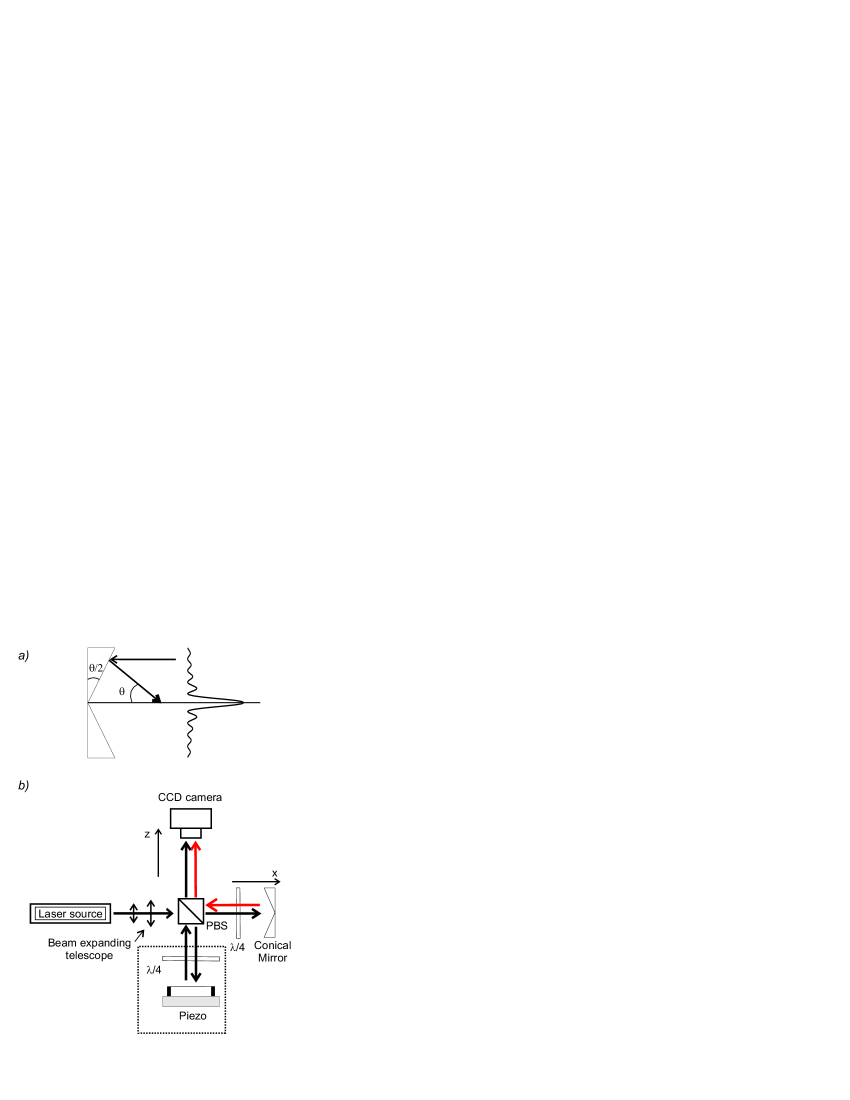
In practical experiments the diffraction free region is limited by the finite extent of the beam. As evidenced by Fig. 1(a), the maximum diffraction free propagation distance depends on the radius of the optical element used for producing the beam and on the axicon angle , and is given by . At propagation distances greater than , the beam diffracts very quickly, spreading the energy over an annular region.
In our experiment, the optical element used to generate the Bessel beam is a conical mirror with a radius of and an apex angle of . The mirror parameters correspond to a non-diffractive distance of and lead to the phase and group velocities exceeding by .
III Spatial Characterization
The non-diffractive propagation was verified by spatial characterization of the Bessel beam. The experimental setup used for these measurements is shown in Fig. 1(b). The light source is a continuous wave (CW) He:Ne laser operating at . The horizontally polarized beam is first expanded so that the resulting collimated light has a waist slightly larger than the diameter of the conical mirror, and then is transmitted through a polarizing beamsplitter (PBS). After the PBS, the Gaussian beam passes through a waveplate, reflects off the conical mirror, passes through the waveplate a second time, changing to a vertical polarization, and is reflected by the PBS. In this way, 65% of the Gaussian beam power is converted into a nondiffractive beam.
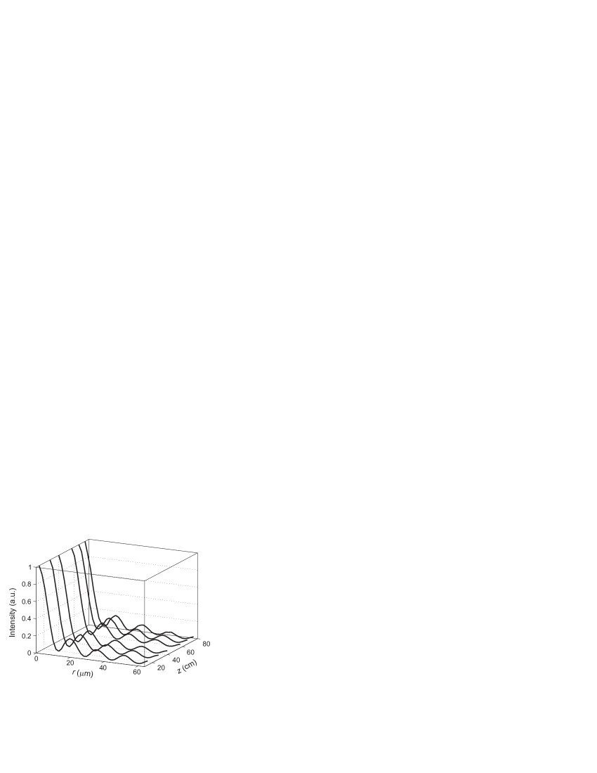
The intensity profile at various positions along the propagation axis was recorded using a CCD camera. A microscope was constructed to magnify the intensity profile by a factor of 3.5 so the camera could resolve fine transverse features of the diffraction pattern. The different radial intensity profiles recorded are shown in Fig. 2 and are almost identical over the entire diffraction free region with a central peak width which is consistent with the theoretical expectation of , where 2.405 is the first zero of the Bessel function.
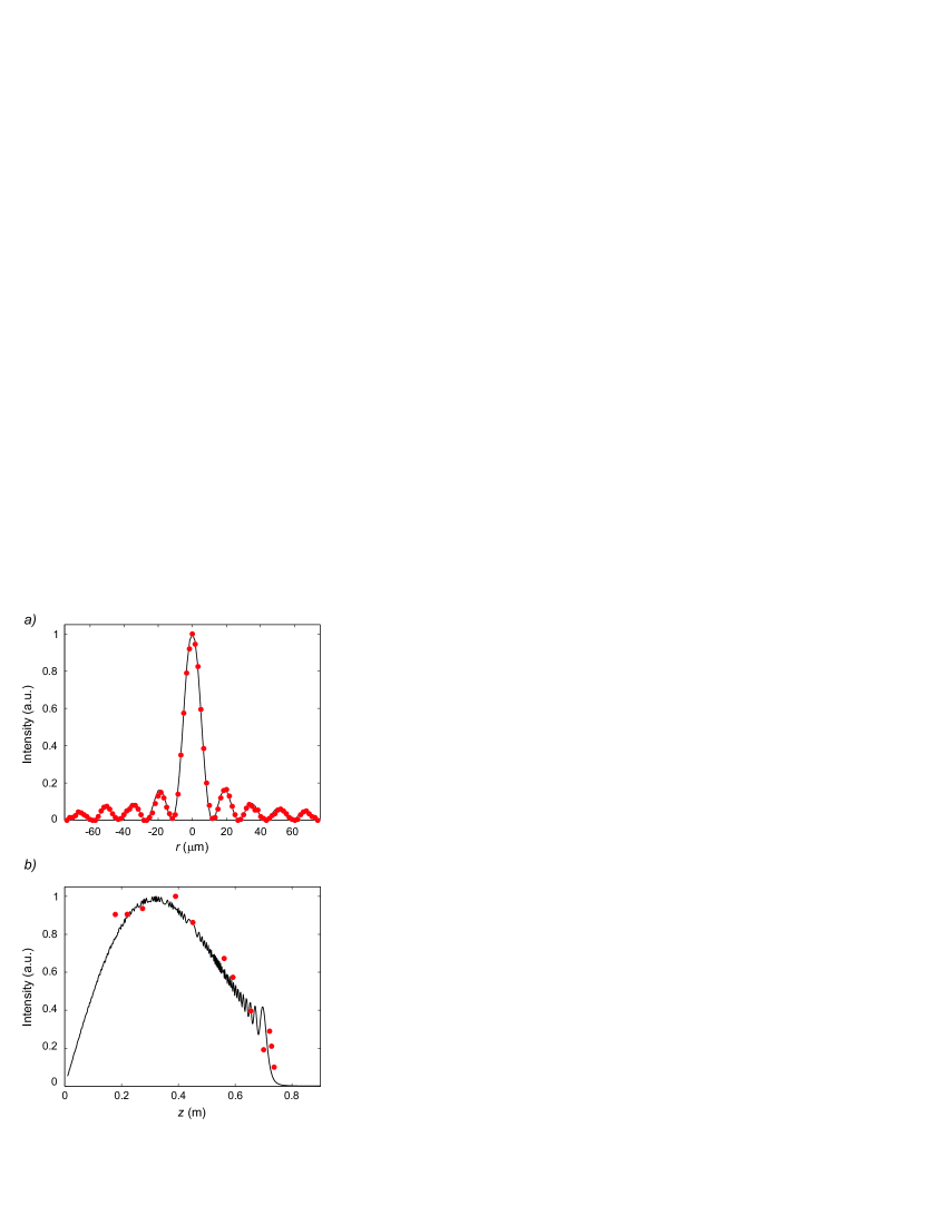
We compared the measured intensity pattern with the pattern calculated numerically by the Rayleigh-Sommerfield diffraction integral Goodman (Fig. 3(a)). For this calculation we assumed the amplitude transmission function of the mirror is given by:
| (2) |
The intensity of the central peak as a function of the propagation distance is shown in Fig. 3(b) together with a the numerical prediction. The central peak intensity behavior is determined by the fact that the light that constructively interferes to create the peak at a longitudinal position arrives from a region of the mirror that has a circumference of . The intensity thus grows linearly for small values of and then decreases when the intensity decrease of the Gaussian profile of the input beam is more rapid then the linear increase of the circumference. The oscillations at the end of the curve are due to the Fresnel diffraction from the outer edge of the mirror.
The 73-cm non-diffractive distance estimated with geometrical optics agreed with that obtained from the numerical calculation and with the experimental results.
IV Temporal Characterization
The phase and group velocities in free space were measured in order to verify that the propagation of the Bessel beam exceeds the speed of light. We implemented an interferometric design using CW light for the phase velocity measurement, and femtosecond pulses for the group velocity measurement. The design, shown in Fig. 1b, is a mixed Michelson interferometer, with a plane mirror in one arm and a conical mirror in the other. In the output channel of the interferometer we placed a CCD camera to record the on-axis intensity as a function of the camera’s longitudinal position . We placed a waveplate into each arm to permit independent manipulation of the intensity of the two beams.
This arrangement allowed us to compare the group and phase velocities of the Bessel beam relative to those of the Gaussian beam (that are equal to ) and to observe the relatively small superluminal effect expected.
IV.1 Phase Velocity Measurement
Gaussian and Bessel beams have both the same frequency but different phase velocities, and , respectively, along the direction. Thus they will show interference fringes spaced at . In our case, with , , we find .
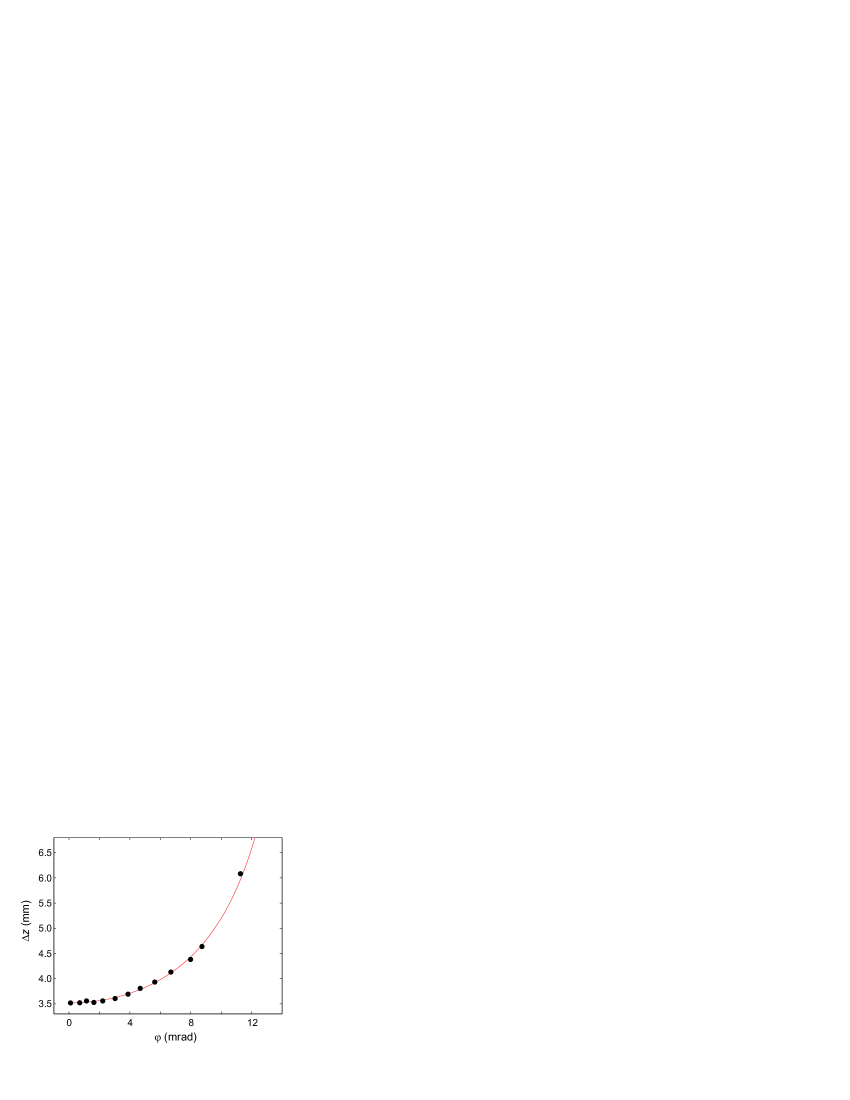
Measuring the spacing of the interference fringes thus yields the magnitude of . In order to determine the sign of , and hence whether the Bessel beam is propagating superluminally, we varied the angle between the direction of propagation of the Gaussian and Bessel beam. By doing so, we set the phase velocity component of the Gaussian beam in the direction of propagation of the Bessel beam to . If the phase velocity of the Bessel beam exceeds that of the Gaussian beam then with increasing between , the interference fringe spacing should also increase. Experimentally, we aligned the Gaussian beam along the optical rail and manipulated by slightly tilting the conical mirror. We determined the value of by displacing the CCD along the optical rail and recording the relative transverse positions of the centres of the two beams at each location. Figure 4 displays the measured interference period as a function of together with a theoretical fit in which the axicon angle was the variable parameter. In particular, note that with increasing misalignment, is increasing, indicating that the phase velocity of the Bessel beam is higher than that of the Gaussian beam. The data give a phase velocity of which is consistent with the expected value , corresponding to an axicon angle of .
IV.2 Group Velocity Measurement
The group velocity measurement was performed using 200 fs pulses at from a Ti:Sapphire mode-locked laser pumped by a solid-state laser. The optics were replaced to accommodate the new wavelength. The Gaussian and Bessel beams were aligned with each other to within .
The intensity in the output channel of the interferometer was measured with the CCD camera. When there is no temporal overlap between the Gaussian and the Bessel pulse, the CCD measured the sum of the intensities of the two pulses. On the other hand, when the pulse arrival was simultaneous, the intensity was affected by interference. Suppose that for some configuration of the interferometer the CCD is located in a position of maximum visibility. If the camera is now translated along the propagation axis away from the PBS by a distance of , the interferometer arm with the planar mirror must be moved by a distance in order to restore the same visibility. Therefore, the Bessel pulse travels an extra distance of in the time the Gaussian pulse travels a distance of , giving
| (3) |
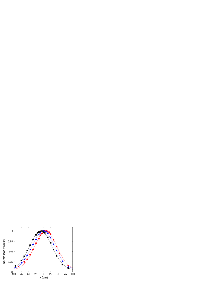
In the experiment, we acquired several pairs for which the interference visibility is optimized. The interference was observed by scanning the plane mirror over a distance of wavelengths with a piezoelectric transducer. For a given position of the camera, the interference visibility over a range of plane mirror positions was evaluated (Fig. 5)
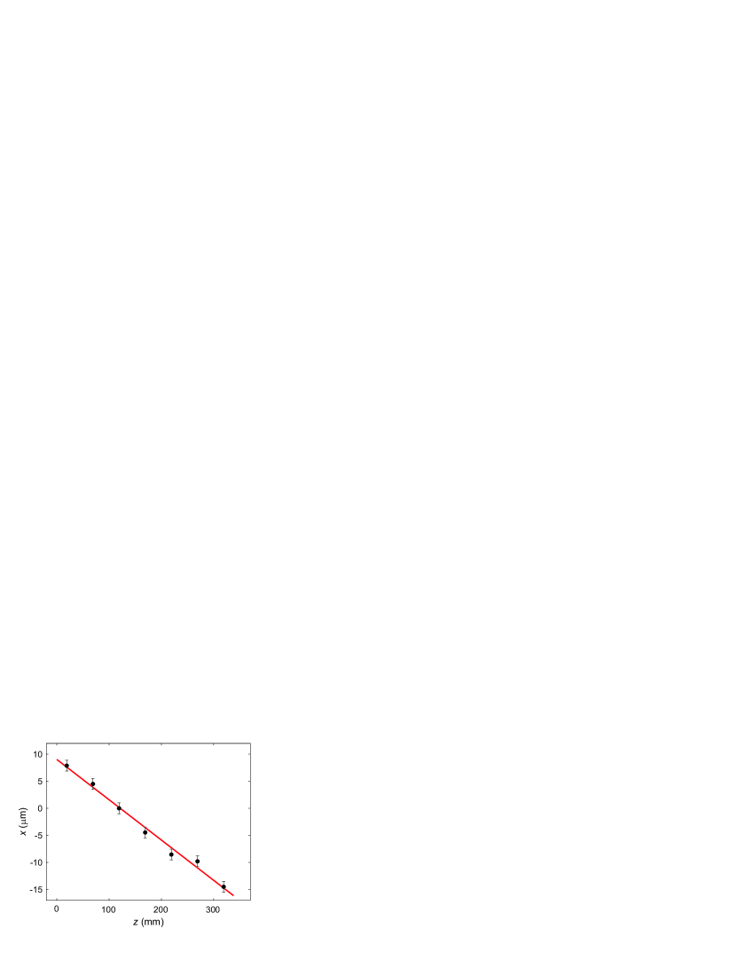
The linear relationship predicted by Eq. (3) is evidenced by Fig. 6, and is characterized by a linear regression slope . The negativity of the slope indicates that the relative path length of the Gaussian beam had to be reduced as the overall travel distance increased (i.e. smaller values), which corresponds to a superluminal group velocity, . This velocity corresponds to the apex angle of .
V Conclusion
We have spatially and temporally characterized an optical Bessel beam produced using a conical mirror propagating in free space.
We ascertained the beam to have a constant peak size over the propagation distance determined by the properties of the conical mirror.
The phase and group velocities of the beam were determined with an interferometric setup to be superluminal, with values of and , respectively, which is consistent with the theoretical prediction.
Acknowledgements
This work was supported by NSERC, CFI, AIF, Quantum and CIFAR (A.L.);
References
- (1) J. Durnin, J. Opt. Soc. Am. A 4, 651 (1987).
- (2) V.N. Belyi, N.S. Kazak, N.A. Khilo, Opt. Comm. 162, 169 (1999)
- (3) V.N. Belyi, N.S. Kazak, N.A. Khilo, Quantum Electron. 28, 522 (1998)
- (4) S. Orlov, A. Stabinis, V. Smilgevicius, G. Valiulis, A. Piskarskas, Optics Letters 32, 68 (2007)
- (5) P. Di Trapani, A. Beržanskis, S. Minardi, S. Sapone, W. Chinaglia, Phys. Rev. Lett. 81, 5133 (1998)
- (6) S. Longhi, Phys. Rev. E 69, 016606 (2004)
- (7) A.P. Piskarskas, V. Smilgevicius, A.P. Stabinis, Applied Optics 36, 7779 (1997)
- (8) T. Wulle, S. Herminghaus, Phys. Rev. Lett. 70, 1401 (1993)
- (9) J. Arlt, K. Dholakia, L. Allen, M. J. Padgett, Phys. Rev. A 60, 2438 (1999)
- (10) D. Ding, J. Y. Lu, Phys. Rev. E 61, 2038 (2000)
- (11) O. Jedrkiewicz, J. Trull, G. Valiulis, A. Piskarskas, C. Conti, S. Trillo, P. Di Trapani, Phys. Rev. E 68, 026610 (2003)
- (12) V. E. Peet, R. V. Tsubin, Phys. Rev. A 56, 1613 (1997)
- (13) A. Averchi, D. Faccio, R. Berlasso, M. Kolesik, J.V. Moloney, A. Couairon, P. Di Trapani, Phys. Rev. A 77, 021802(R) (2008)
- (14) G. Milne, K. Dholakia, D. McGloin, K. Volke-Sepulveda, P. Zem nek, Opt. Express 15, 13972 (2007)
- (15) V. Garcés-Chávez, D. McGloin, H. Melville, W. Sibbett, K. Dholakia, Nature 419, 145 (2002)
- (16) M.D. Summers, J.P. Reid, D. McGloin, Opt. Express 14, 6373 (2006)
- (17) J. Arlt, K. Dholakia, J. Soneson, E.M. Wright, Phys. Rev. A 63, 063602 (2001)
- (18) V. Garcés-Chávez, K. Volke-Sepulveda, S. Chávez-Cerda, W. Sibbett, K. Dholakia, Phys. Rev. A 66, 063402 (2002)
- (19) J. Fan, E. Parra, K.Y. Kim, I. Alexeev, H.M. Milchberg, J. Cooley, T.M. Antonsen, Phys. Rev. E 65, 056408 (2002)
- (20) S.A. Tatarkova, W. Sibbett, K. Dholakia, Phys. Rev. Lett. 91, 038101 (2003)
- (21) I.V. Arakelyan, N. Chattrapiban, S. Mitra, W.T. Hill III, Phys. Rev. A 75, 061604(R) (2007)
- (22) K. S. Lee, J. P. Rolland, Opt. Lett. 33, 1696 (2008)
- (23) Lu Jian-yu, T.K. Song, R.R. Kinnick, J.F. Greenleaf, IEEE Trans. Med. Imag. 12, 819 (1993)
- (24) D. Mugnai, A. Ranfagni, R. Ruggeri, Phys. Rev. Lett. 84, 4830 (2000)
- (25) H. Ringermacher, L.R. Mead, Phys. Rev. Lett. 87, 059402 (2001)
- (26) N.P. Bigelow, C.R. Hagen, Phys. Rev. Lett. 87, 059401 (2001)
- (27) I. Alexeev, K.Y. Kim, H.M. Milchberg, Phys. Rev. Lett. 88, 073901 (2002)
- (28) J.F. Fortin, G. Rousseau, N. McCarthy, M. Piche, Proc. of SPIE 4833, 876 (2002)
- (29) J.H. McLeod, J. Opt. Soc. Am. A 44, 592 (1954)
- (30) J.W. Goodman, Introduction to Fourier Optics, 2nd edition (McGraw-Hill, 1996).