All-electrical detection of the relative strength of Rashba and Dresselhaus
spin-orbit interaction in quantum wires
Abstract
We propose a method to determine the relative strength of Rashba and Dresselhaus spin-orbit interaction from transport measurements without the need of fitting parameters. To this end, we make use of the conductance anisotropy in narrow quantum wires with respect to the directions of an in-plane magnetic field, the quantum wire and the crystal orientation. We support our proposal by numerical calculations of the conductance of quantum wires based on the Landauer formalism which show the applicability of the method to a wide range of parameters.
pacs:
71.70.Ej, 73.20.Fz, 73.63.NmWith conventional electronics expected to reach critical boundaries for its performance soon, a new field of research utilizing the spin of the electron has evolved in recent years. Within this field called spintronics much attention has been focussed on spin-orbit interaction (SOI) because it provides a way of controlling the spin degree of freedom electrically in (non-magnetic) semiconductor-based systems without the need of external magnetic fields. However, SOI in two-dimensional electron gases (2DEG) is a double-edged sword, since spin relaxation in disordered 2DEGs, which is typically dominated by the D’yakonov-Perel’ (DP) mechanism Dyakonov1971 , is enhanced for strong SOI. Since many promising semiconductor spintronics device proposals, e.g. the Datta-Das spin field effect transistor (SFET) Datta1990 , rely on coherent spin transport, it is desirable to efficiently suppress the spin relaxation. In 2DEGs formed in III-V semiconductor heterostructures, there are typically two main SOI contributions, namely, Rashba SOI due to structural inversion asymmetry Rashba1960 and Dresselhaus SOI due to bulk inversion asymmetry of the semiconductor crystal Dresselhaus1955 . An interesting situation occurs when the -linear Rashba and Dresselhaus terms are of equal strength, i.e. . Then, spin is a good quantum number and DP spin relaxation is absent Schliemann et al. (2003). Lately there has been much effort into this direction both theoretically with new device proposals Schliemann et al. (2003); Cartoixà et al. (2003), and experimentally with the aim to achieve Giglberger et al. (2007). Naturally, a precise control of the ratio is essential for spin manipulation and the operability of many spintronics devices. Since the strength of the Dresselhaus SOI is fixed in a given quantum well the most promising tool to modify is the control of the Rashba SOI strength via gate voltages Nitta et al. (1997).
To operate spintronics setups relying on the value of requires the ability to measure this ratio with high accuracy. Although it is possible to determine by using optical techniques Giglberger et al. (2007); Ganichev et al. (2004); Meier et al. (2007), this is not always an option. If, e.g., the semiconductor heterostructure is covered by a top gate used to tune the Rashba SOI strength, it is very difficult to carry out optical measurements; therefore methods are highly desirable that allow one to determine the ratio from transport measurements. In principle, this can be achieved by fitting weak antilocalization (WAL) data from magneto-conductance (MC) measurements to analytical predictions Knap et al. (1996); Miller et al. (2003). However, the results usually bear a certain ambiguity, since one has to fit the data with several parameters and the possible error margins are thus quite large.
Hence, in this Letter we propose an alternative, all-electrical method to determine the relative strength, , of Rashba and Dresselhaus SOI from measuring the conductance of narrow quantum wires defined in a 2DEG subject to an in-plane magnetic field. The method is based on the fact, that only for a field parallel to the effective magnetic field due to SOI the weak localization (WL) correction to the conductance survives, while it is suppressed for all other directions. No fit parameters are required, and is straightforwardly related to this specific field direction, where the conductance is minimal.
We numerically calculate the conductance of a disordered quantum wire realized in a 2DEG with SOI linear in momentum. The single-particle Hamiltonian of the quantum wire in -direction reads Łusakowski et al. (2003)
| (1) |
with the effective spin-orbit field
and the external in-plane magnetic field
| (3) |
The vector potential components in arise due to the perpendicular magnetic field whose contribution to the Zeeman effect we neglect. In Eq. (All-electrical detection of the relative strength of Rashba and Dresselhaus spin-orbit interaction in quantum wires) and is the Rashba and Dresselhaus SOI strength respectively and / is the angle between the quantum wire/in-plane magnetic field and the direction of the crystal for a zinc-blende heterostructure grown in the direction. The electrostatic potential includes the confining potential for the quantum wire and the disorder potential from static non-magnetic impurities in a region of length .
For the calculations we use a discretized version of the Hamiltonian (1) that allows us to evaluate the transport properties of the wire by computing lattice Green functions. For details see, e.g., Ref. Wimmer et al. (2008).
The dimensionless numerical parameters used in this letter (denoted by a bar) are related to real
physical quantities as follows (for square lattice spacing ): Energy , SOI strengths and . As a typical lengthscale for the simulations we introduce . In the calculations, the disorder potential is modelled by Anderson disorder with strength . The mean free path is given by
, where is the scaled Fermi energy. The conductance
of the wire is obtained by averaging over disorder configurations and unless stated otherwise
the following parameters are fixed : (corresponding to 4 propagating modes for a wire of width ), ,
(i.e. ) and .
To understand the mechanism for the detection of , which requires finite , we first study the conductance of quantum wires at . Specifically we present the MC for two cases, where WAL is suppressed: (a) Rashba and Dresselhaus spin precession lengths larger than the width of the wire , i.e., , and (b) .
In Fig. 1a, we plot for wires with fixed and different widths , showing that for smaller WAL is suppressed, which is in line with earlier experimental results Schäpers et al. (2006) and confirms analytical Kettemann (2007) and numerical treatments Schäpers et al. (2006). Since spin relaxation is essential for WAL, the mechanism for the suppression of WAL can be attributed to an enhancement of the spin-scattering length in narrow wires Kiselev and Kim (2000); Holleitner (2006), and more generally, in confined geometries Aleiner (2001); Zaitsev (2005).
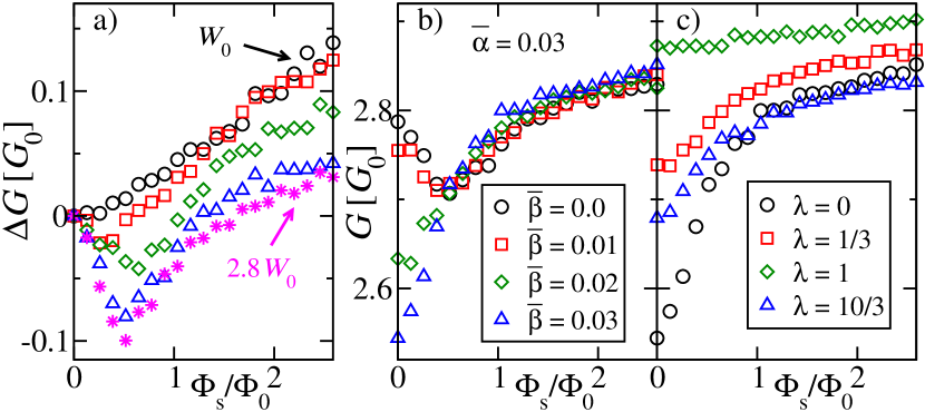
In the case (b), , points uniformly into the []-direction for all -vectors and a so-called persistent spin helix forms Bernevig et al. (2006). There the spin state of an electron is determined only by its initial and final position independent of the exact path in-between. Therefore, charge carriers do not acquire an additional phase due to SOI upon return to their initial positions, resulting in constructive interference of the wavefunctions connected by time reversal, hence WL Pikus and Pikus (1995). This behavior is shown for fixed and but variable in Fig. 1b where we observe that WAL is suppressed for .
In both cases shown in Figs. 1a,b the absence of WAL is caused by the suppression of spin relaxation with the spin relaxation length exceeding the length of the wire , where in the numerical simulation takes the role of the phase coherence length in the experiment.
We now investigate the influence of an additional in-plane magnetic field on the conductance of a quantum wire
where WAL is suppressed. For convenience, we introduce the ratio which is the relative strength of the in-plane magnetic field and the effective magnetic field due to SOI for a -vector along the quantum wire, see Eqs. (All-electrical detection of the relative strength of Rashba and Dresselhaus spin-orbit interaction in quantum wires),(3). In Fig. 1c we show the MC for the case for several values of : The conductance at is enhanced by a finite . The form of the MC curves in Fig. 1c can be understood from the expression for the WL/WAL conductance correction from diagrammatic perturbation theory Hikami1980 . It is of the form , where the first (singlet) term contributes positively to the conductance and is responsible for the typical WAL peak in systems with SOI. It is unaffected by DP spin
relaxation but suppressed by an in-plane magnetic field Mal’shukov
et al. (1997).
The second (triplet) term gives a negative conductance
contribution and is suppressed for short spin relaxation times Hikami1980 . For the parameters used
in Fig. 1c, is suppressed for , thus in the respective curves shown in Fig. 1c only the triplet term is present in resulting in positive MC . While for we observe WL due to , increasing gives rise to a transition to at and back to WL for . This can be understood by the change of the spin relaxation in the system: For finite in a direction different from (), the resulting magnetic field will not be uniformly in the direction anymore, but cause spin relaxation, which is strongest for comparable strengths of and and yields a reduction of the triplet term (green diamonds in Fig. 1c).
For in-plane magnetic fields which distinctly exceed the effective magnetic field (), on the other hand, WL is restored to some degree (blue triangles in Fig. 1c) since the resulting is strongly aligned in the direction of and spin relaxation is reduced again. The enhancement of in an in-plane magnetic field is anisotropic with respect to the direction of . For , spin remains a good quantum number due to . Thus DP spin relaxation is absent, resulting in WL. This behavior can be observed in Fig. 2a, where at is shown for a slightly different geometry.
Contrary to the case considered here, in systems showing WAL for , the transition from WAL to WL is observed with increasing Meijer et al. (2004, 2005) due to the reduction of the singlet term caused by .
We now investigate the conductance subject to an in-plane magnetic field in quantum wires where WAL is suppressed due to a much smaller width with respect to the spin precession lengths.
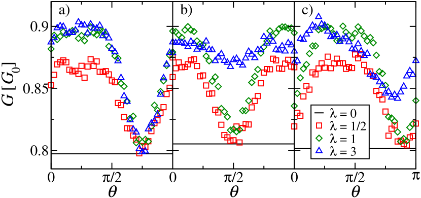
In Fig. 2 we plot the dependence of the conductance on the angle for three different ratios . In order to understand the increase of at for all but one angle , we consider the case of a strictly one-dimensional quantum wire (1DQW) with SOI. We follow this approach, since for the system investigated in Fig. 2 the width of the wire is much smaller than the phase coherence length, a situation where it is sufficient to take into account only the transversal zero-mode for the calculation of the quantum correction to the conductance Kettemann (2007). A disordered 1DQW exhibits WL even if SOI of the Rashba and/or Dresselhaus type is present, since the spin is a conserved quantity in this limit. The effective magnetic field experienced by the electrons is exactly opposite for electrons travelling in or -direction, and thus no additional phase in the wavefunction is acquired by electrons returning to their original position. However, a finite in-plane magnetic field can suppress the WL and induce an increase in the conductance. If , the direction of the total magnetic field, , is different for electrons travelling in or -direction, resulting in spin relaxation and an increase of (reduction of WL). A minimum in exists for , where no DP spin relaxation takes place since spin is still a good quantum number. In Fig. 2 we observe that the minimum of appears at the angle which corresponds to the respective effective magnetic field direction for a -vector along the wire direction.
In view of the results of Fig. 2, we conjecture that also for a quasi-one-dimensional quantum wire with the angle at which the minimum in the conductance appears is given by the direction of the effective magnetic field for a -vector along the wire direction :
| (4) |
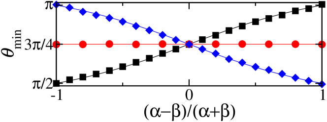
In Fig. 3, we plot Eq. (4) for three different wire orientations (solid lines), whose validity is nicely confirmed by extracting from the numerical dependence (such as Fig. 2) for different ratios of (symbols) with fixed . In order to use this feature for the determination of the ratio we suggest to measure for quantum wires oriented either along the [100] or the [010]-direction. Then the angle of the minimum conductance directly provides the unambiguous value for the relative strength and signs of and . Choosing, e.g. this ratio is given by , which is representative for the whole sample, since the influence of the lateral confinement on the strength of the SOI is negligible Guzenko et al. (2006). Considering quantum wires realized in an InAlAs/InGaAs heterostructure (typical values , ) and fixing the width nm, we see that the parameters used in Fig. 3 (nm, T and Vm) are well in reach of present day experiments Meijer et al. (2004); Bergsten et al. (2006).
We have neglected effects due to the cubic Dresselhaus SOI term, which becomes increasingly important for wide quantum wells. In general, it induces additional randomization of the spin state, which for the case of a very strong cubic Dresselhaus contribution can result in the absence of the suppression of WAL Pikus and Pikus (1995). Nevertheless, since cubic Dresselhaus coupling is smallest for -vectors along [100] or [010] directions, we have neglected it for the determination of , since in our proposal the quantum wire is assumed to be oriented in one of those directions. However, in contrast to a 1DQW, it might have an effect on , if it is comparable in strength to the linear term.
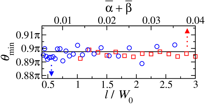
In order to assess possible limitations of this method, we performed calculations varying several parameters, while keeping the ratio constant. In Fig. 4, we show that Eq. (4), , is fulfilled for a wide range of both SOI strengths (squares) and mean free paths (circles). Further numerical calculations, upon increasing the number of transverse orbital modes in the wire up to 13, showed that Eq. (4) still holds true (not presented here).
In conclusion we have shown, that Eq. (4), derived for a 1DQW, provides a
valuable tool to determine the ratio also for a quantum wire with several transversal
modes, only requiring , i.e. a suppression of WAL due to the
confinement Schäpers et al. (2006). For increasing width, evolves into a behavior
typical of a 2DEG Mal’shukov
et al. (1997, 1999), where is only anisotropic,
if both . Opposed to the narrow quantum wires considered where
, Eq. (4), is a function of and ,
in a 2DEG minimum of the conductivity appears either at or
, depending on the sign of the product , but independent of
the ratio .
Apart from the condition , the method should be applied at
sufficiently small (). As can be seen from Fig. 2b,c, when ,
is increased for any , potentially changing the position of (see, e.g., blue triangles in Fig. 2c). Only for the case of shown in Fig. 2a, does not increase, since for any -vector. In this special case the validity of Eq. (4) is not limited to narrow wires and small magnetic fields.
To summarize, in narrow quantum wires which exhibit weak localization even in the presence of spin-orbit coupling, an in-plane magnetic field can suppress the weak localization effect. We employed the unique angular dependence of this effect to suggest a method for the direct and experimental determination of the ratio between Rashba- and Dresselhaus spin-orbit strengths from transport measurements. Its straightforward applicability may help to facilitate the design of semiconductor-based building blocks for spintronics.
Acknowledgements We acknowledge valuable discussions with M. Wimmer, İ. Adagideli and D. Bercioux. JN and MK acknowledge financial support from MEXT, MS from JSPS and the Studienstiftung des Deutschen Volkes, and KR from DFG through SFB 689.
References
- (1) M. I. D’yakonov, and V. I. Perel’, Fiz. Tverd. Tela 13, 3581 (1971) [Sov. Phys. Solid State 13, 3023 (1971)].
- (2) S. Datta, and B. Das, Appl. Phys. Lett. 56, 665 (1990).
- (3) E. Rashba, Fiz. Tverd. Tela (Leningrad) 2, 1224 (1960) [Sov. Phys. Solid State 2, 1109 (1960)].
- (4) G. Dresselhaus, Phys. Rev. 100, 580 (1955).
- Schliemann et al. (2003) J. Schliemann, J. C. Egues, and D. Loss, Phys. Rev. Lett. 90, 146801 (2003).
- Cartoixà et al. (2003) X. Cartoixà, D. Z.-Y. Ting, and Y.-C. Chang, Appl. Phys. Lett. 83, 1462 (2003).
- Giglberger et al. (2007) S. Giglberger, et al., Phys. Rev. B 75, 035327 (2007).
- Nitta et al. (1997) J. Nitta, et al., Phys. Rev. Lett. 78, 1335 (1997).
- Ganichev et al. (2004) S. D. Ganichev, et al., Phys. Rev. Lett. 92, 256601 (2004).
- Meier et al. (2007) L. Meier, et al., Nature Phys. 3, 650 (2007).
- Knap et al. (1996) W. Knap, et al., Phys. Rev. B 53, 3912 (1996).
- Miller et al. (2003) J. B. Miller, et al., Phys. Rev. Lett. 90, 076807 (2003).
- Łusakowski et al. (2003) A. Łusakowski, J. Wróbel, and T. Dietl, Phys. Rev. B 68, 081201(R) (2003).
- Wimmer et al. (2008) M. Wimmer, M. Scheid, and K. Richter, arXiv:0803.3705v1 (2008), to appear in the Encyclopedia of Complexity and System Science.
- Schäpers et al. (2006) T. Schäpers, et al., Phys. Rev. B 74, 081301(R) (2006).
- Kettemann (2007) S. Kettemann, Phys. Rev. Lett. 98, 176808 (2007).
- Kiselev and Kim (2000) A. A. Kiselev and K. W. Kim, Phys. Rev. B 61, 13115 (2000).
- Holleitner (2006) A. W. Holleitner, et al., Phys. Rev. Lett. 97, 036805 (2006).
- Aleiner (2001) I. L. Aleiner, and V. I. Fal’ko, Phys. Rev. Lett. 87, 256801 (2001).
- Zaitsev (2005) O. Zaitsev, D. Frustaglia, and K. Richter, Phys. Rev. Lett. 94, 026809 (2005).
- Bernevig et al. (2006) B. A. Bernevig, J. Orenstein, and S.-C. Zhang, Phys. Rev. Lett. 97, 236601 (2006).
- Pikus and Pikus (1995) F. G. Pikus and G. E. Pikus, Phys. Rev. B 51, 16928 (1995).
- (23) S. Hikami, A. I. Larkin, and Y. Nagaoka, Prog. Theor. Phys. 63, 707 (1980).
- Mal’shukov et al. (1997) A. G. Mal’shukov, K. A. Chao, and M. Willander, Phys. Rev. B 56, 6436 (1997).
- Meijer et al. (2004) F. E. Meijer, et al., Phys. Rev. B 70, 201307(R) (2004).
- Meijer et al. (2005) F. E. Meijer, et al., Phys. Rev. Lett. 94, 186805 (2005).
- Guzenko et al. (2006) V. A. Guzenko, et al., Appl. Phys. Lett. 88, 032102 (2006).
- Bergsten et al. (2006) T. Bergsten, et al., Phys. Rev. Lett. 97, 196803 (2006).
- Mal’shukov et al. (1999) A. G. Mal’shukov, V. A. Froltsov, and K. A. Chao, Phys. Rev. B 59, 5702 (1999).