Multiple radial corrugations in multiwalled carbon nanotubes under pressure
Abstract
Radial elastic corrugation of multi-walled carbon nanotubes under hydrostatic pressure is demonstrated by using the continuum elastic theory. Various corrugation patterns are observed under several GPa, wherein the stable cross-sectional shape depends on the innermost tube diameter and the total number of concentric walls. A phase diagram is established to obtain the requisite values of and for a desired corrugation pattern among choices. In all corrugation patterns, the cylindrical symmetry of the innermost tube is maintained even under high external pressures.
pacs:
61.46.Fg, 62.50.-p, 64.70.Nd, 81.05.Tp1 Introduction
Carbon nanotubes show great promise for use as nanoscale materials due to their high tensile strength in the axial direction and remarkable flexibility in bending [1]. Another important characteristic of carbon nanotubes is their high flexibility in the radial direction. In fact, the magnitude of radial stiffness of an isolated carbon nanotube is considerably less than that of axial stiffness [2], which allows a reversible change in the cross-sectional shape on applying a hydrostatic pressure. Such a pressure-induced radial deformation and the associated change in vibrational modes are useful to probe the structural properties of nanotubes. More interestingly, this deformation alters other physical properties of nanotubes and related materials, such as electronic [3, 4, 5, 6, 7, 8, 9] and optical [10, 11, 12, 13, 14, 15] properties. For instance, application of hydrostatic pressures have been found to induce drastic changes in the electrical conductance of nanotubes [16, 17], implying the relevance of radial deformations in carbon nanotube applications.
Thus far, many experimental and theoretical studies have been carried out on radial deformations of carbon nanotubes induced by hydrostatic pressures [18, 19, 20, 21, 22, 24, 25, 26, 23, 27, 28, 29, 30, 31, 32, 33], most of which have focused on single-walled nanotubes (SWNTs) and their bundles. Successive investigations have revealed flattening and polygonalization in the cross section of SWNTs under pressures of the order a few GPa [10, 19], in which the stable cross-sectional shape is determined by minimizing the elastic energy of the cylindrical tube under constraints. Employing these transformation properties for developing nanoscale pressure sensors has also been suggested [34, 35].
As compared to the intensive studies carried on SWNTs, studies on the radial elastic deformation of multiwalled nanotubes (MWNTs) are lagging behind. An important feature of MWNTs is that they consist of a set of concentric graphite cylindrical walls mutually interacting via the van der Waals (vdW) forces. This core-shell structure produces an encapsulation effect under external pressure, wherein the outer walls collectively function as a protective shield. In principle, the encapsulation effect enhances the radial stiffness of MWNTs. However, this is less obvious if the number of concentric walls, , is much greater than unity. For the latter case, outside walls possess large diameters so that the application of a hydrostatic pressure leads to a mechanical instability in the outer walls. This instability is, nonetheless, compensated by the relative rigidity of the inner walls with small diameters. These two competing effects imply the possibility of a new cross-sectional shape transition of MWNTs induced by hydrostatic pressure, whereas such the transition is still to be explored.
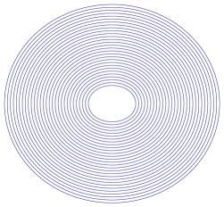

In this article, we demonstrate a novel radial deformation, called the radial corrugation, of MWNTs with under hydrostatic pressure. In the corrugation mode, outside walls show significant radial corrugation along the circumference, while the innermost tube maintains its cylindrical symmetry (Fig. 1(b)). We found various corrugation modes can be obtained by tuning the innermost tube diameter and the number of constituent walls , which is a direct consequence of the core-shell structure of MWNTs. These results provide useful information for developing nanofluidic [36, 37, 38, 39] or nanoelectrochemical [40, 41] devices whose performance depends crucially on the geometry of the inner hollow cavity of nanotubes.
2 Method
2.1 Mechanical energy of MWNT
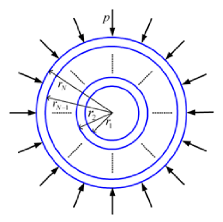
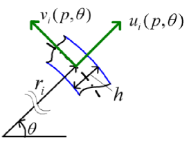
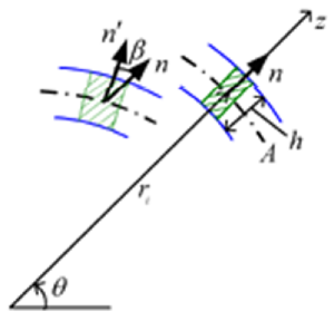
The stable cross-sectional shape of a MWNT under a hydrostatic pressure can be evaluated by using the continuum elastic theory for cylindrical shells. The effectiveness of the continuum approximation for modeling MWNTs has been demonstrated in a series of studies previously [42, 43, 44, 45, 46], particularly for multiwalled nanotubes containing a large number of carbon atoms. In the continuum approximation, the mechanical energy of a MWNT per unit length in the axial direction is the sum of the deformation energy of all concentric walls, the interaction energy of all adjacent pairs of walls, and the potential energy of the applied pressure. All the three energy terms are functions of and the deformation amplitudes and , which denote the radial and circumferential displacements, respectively, of a surface element of the th wall (see Fig. 2). Thus, can be written as
| (1) |
It should be noted that our theoretical model assumes a very long, straight MWNT with both ends being free. On applying hydrostatic pressure, therefore, the tube is freely (but slightly) elongated in the longitudinal direction because of the absence of reactive force at the ends. This means the absence of longitudinal deformation in our theoretical condition, which allows us to consider only the cross sectional deformation under hydrostatic pressure.
An explicit form of the function (1) is obtained as follows. Firstly, of all concentric walls is expressed as
| (2) |
where . In Eq. (2), the first term in the curly brackets describes the stretching energy of the walls in the tangential direction and the second term describes the bending energy. (The derivation of the formula (2) involves some complex calculations and is presented in Appendix.) The two parameters and characterise the mechanical stiffness of the walls for in-plane stretching and bending, respectively. They are defined as follows:
where is Young’s modulus ( TPa), is Poisson’s ratio (), and indicates the thickness of individual walls ( nm). Hereafter, indicates the radius of the th wall in the absence of pressure; thus . The spacing between adjacent walls is set to be nm according to Ref. [47].
Secondly, the explicit form of is given as
| (3) |
where the vdW interaction coefficients are functions of and and given as follows [46]:
Here we set
in which denotes the chemical bond length between neignbouring carbon atoms within a layer ( nm), and and are the parameters that determine the vdW interaction between two layers ( meV and nm) [48].
Finally, we consider an explicit form of . Since a cylindrical shell subjected to is a conservative system, the change in the potential energy as the cross section of the MWNT deforms is the negative of the work done by the pressure during the deformation. Hence, we have
| (4) |
where is the cross-sectional area after deformation. A simple calculation yields the following expression:
| (5) |
Refer Appendix for the derivation of the formula (5).
2.2 Critical pressure and deformation mode
Our aim is to evaluate the critical pressure above which the circular cross section of MWNTs is elastically deformed into non-circular one. To carry out the analysis, we decompose the radial displacement terms as . Here, indicates a uniform radial contraction of the th wall at , whose magnitude is proportional to . The describes a deformed, non-circular cross section observed just above . Similarly, we can write , since at .
Applying the variation method to with respect to and , we obtain a system of linear differential equations given by
| (6) |
and
| (7) |
where and . In deriving Eqs. (6) and (7) through the calculus of variation, quadratic or cubic terms in and were omitted since we consider elastic deformation with sufficiently small displacements. In addition, the terms consisting only of and are also omitted; the sum of such terms should be equal to zero since represents an equilibrium circular cross-section under .111The fact that the sum equals zero determines the function form of .
Clearly, , and their derivatives are periodic in . Hence, general solutions of Eqs. (6) and (7) are given by the Fourier series expansions
Introduction into Eqs. (6) and (7) results in the matrix equation , in which the vector consists of and with all possible and , and the matrix involves one variable as well as parameters such as , , etc. It should be noted that, due to the orthogonality of and , the matrix can be expressed by a block diagonal matrix of the form . Here, is a submatrix that satisfies , where is a -column vector composed of and . As a result, the secular equation that provides nontrivial solutions of Eqs. (6) and (7) is rewritten by
| (8) |
Solving Eq. (8) with respect to , we obtain a sequence of discrete values of each of which is the smallest solution of . Among these values of s, the minimum one serves as the critical pressure that is associated with a specific integer . From the definition, the associated with a specific allows only and be finite, but it requires and . Immediately above , therefore, the circular cross section of MWNTs becomes radially deformed as described by
where the value of is uniquely determined by the one-to-one relation between and .
3 Radial corrugations of MWNTs
3.1 Cross-sectional view
Figure 1 illustrates cross-sectional view of two typical deformation modes — (a) elliptic and (b) corrugation modes — of a MWNT with nm. For Fig. 1(a) and 1(b), and , respectively. In the elliptic mode, all constituent walls are radially deformed. On the contrary, in the corrugation mode, outside walls exhibit significant deformation, while the innermost wall maintains its circular shape. The deformation mode observed just above depends on the values of and for the MWNT under consideration. It will be shown below that larger and smaller favor a corrugation mode with larger .
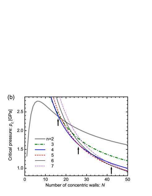
3.2 Critical pressure curve
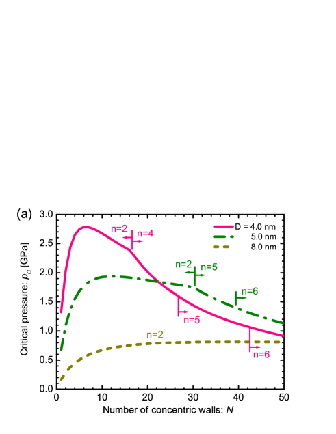
Figure 3 (a) shows as a function of for various values of . The mode index of the deformation mode observed just above for fixed and is also shown. For all , increase with followed by a slow decay, except for the case of nm. The increase in in the region of small is attributed to the enhancement of radial stiffness of the entire MWNT by encapsulation. This stiffening effect disappears with further increase in , resulting in the decay of . A decay in implies that a relatively low pressure becomes sufficient to produce radial deformation, thus indicating an effective “softening” of the MWNT. Such a decay is also observed for nm and larger , in principle, if a sufficiently large is considered (but omitted in Fig. 3 (a)). The two contrasting behaviors, stiffening and softening, are different manifestations of the encapsulation effect of MWNTs.
We observe in Fig. 3 (a), only the elliptic deformation is realised in the stiffened region, while certain radial corrugations with are formed in the softened region. The observation of the former phenomenon can be understood by considering the radial deformation of a single-walled cylindrical shell. In the stiffened region, since is very small, the relation holds. This implies that in this region, a MWNT behaves effectively as a single-walled cylindrical shell with wall thickness . For a single-walled shell, the secular equation gives solutions of
Hence, always has the minimum value when . This scenario applies to MWNTs if is sufficiently small, resulting in the elliptic mode of in the stiffened region.
The most striking observation is the successive transformation of the cross section with an increase in . For nm, for example, the deformation mode observed just above jumps abruptly from to at , followed by successive emergences of higher corrugation modes with larger . The critical number of walls separating the elliptic phase from the corrugation phase is identified to that yields a cusp in the curve of . In contrast, no singularity is observed in the curve of at values of , which separate two neighboring corrugation phases. We emphasize that at these phase boundaries, one additional wall induces a drastic change in the cross-sectional shape of the MWNT under the hydrostatic pressure. These transitions in originate from the two competing effects inherent in MWNTs with , that is, the relative rigidity of the inner walls and the mechanical instability of outer walls. A large discrepancy in the radial stiffness of the inner and outer walls gives rise to a maldistribution of the deformation amplitudes of concentric walls interacting through the vdW forces, which consequently produces an abrupt change in the observed deformation mode at some .
Figure 3(b) explains the absence of the corrugation mode of in MWNTs with nm. This figure shows the -dependence of the solutions for the secular equation . As mentioned earlier, the secular equation gives various values of , each of which is associated with a specific mode index . Among the values of , the minimum value gives the critical pressure just above which cross-sectional deformation takes place. Figure 3(b) depicts the -dependence of for several values, where the innermost tube radius is fixed to be nm. For , the values of for are less than those for , which implies that the elliptic mode occurs for MWNTs with . However, for , the minimum corresponds to , implying the occurrence of the corrugation mode of . It should be noted that for , can never attain the minimum value at any . This is why the corrugation mode of cannot be observed for MWNTs with nm. A parallel discussion accounts for the absence of the modes of for nm and the corrugation modes for nm within the range of we have considered. It also follows from Fig. 3(b) that the cusps in the curves occur only at the phase boundary separating the elliptic phase from a corrugation phase , while no singularity appears at the boundaries of between neighbouring corrugation phases.

3.3 Phase diagram
Figure 4 shows a phase diagram of the radial deformation modes in MWNTs observed above . The bottom region below a chain of solid circles (colored in gray online) corresponds to the elliptic phase, and the top regions surrounded by other symbols indicate the corrugation phases associated with . It is clearly observed that above the elliptic phase, multiple corrugation modes are formed depending on the values of and . It is also observed that smaller and larger favor corrugation modes to the elliptic modes. Furthermore, larger yield higher corrugation modes with larger . To our knowledge, this is the first demonstration of the phase diagram of the multiple corrugation transitions, while conditions for the higher modes to occur were previously argued [23]. A quantitative examination of the present results by sophisticated atomistic simulations [49, 50, 51] may provide a better understanding of the corrugation properties of MWNTs.
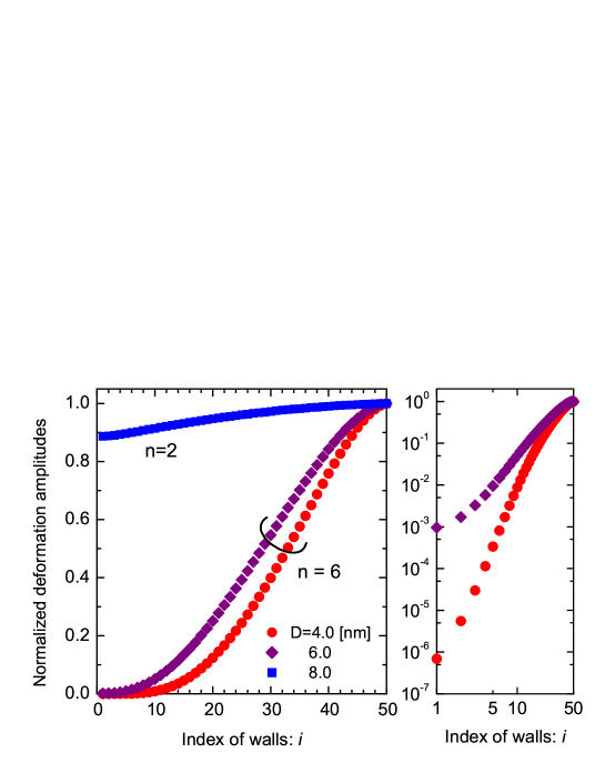
4 Persistent cylindrical geometry of the innermost tube
We have mentioned that in all corrugation modes, the innermost tube maintains its cylindrical symmetry. This persistence of cylindrical symmetry can be demonstrated by plotting the deformation amplitudes . Figure 5 shows the normalized deformation amplitudes, , of individual concentric walls for the MWNT with . The innermost and outermost walls correspond to and , respectively, and the associated is also shown. Double-logarithmic plots of the same data for the corrugation mode are also presented in the right-hand-side figure. The figures clearly show that in the corrugation mode, the deformation amplitudes of the innermost tube are significantly smaller than those of the outer walls by several orders of magnitude. The persistence of cylindrical symmetry of the innermost tube will be useful in developing nanotube-based nanofluidic [36, 37, 38, 39] or nanoelectrochemical devices [40, 41], since both utilize the hollow cavity within the innermost tube. In fact, several different types of intercalated molecules such as diatomic gas, water, organic, and transition metal molecules are known to fill the innermost hollow cavities of nanotubes [37] and exhibit various intriguing behaviors that are distinct from those of the corresponding bulk systems [52, 53, 54]. For the intercalates, the innermost tube of MWNTs with functions as an ideal protective shield, since it maintains its cylindrical geometry even under high external pressures up to an order of GPa.
5 Discussions
We have observed that radial corrugation modes yield a large difference in the deformation amplitudes between the outer and inner walls. Hence, the modes disturb the equal spacings between the concentric walls in MWNTs. This possibly affects electronic and vibrational properties of the entire nanotube, thus triggering a change in its electronic and thermal conductance. Such pressure-induced changes, if they occur, are of practical use for developing MWNT-based pressure sensors [34, 35]. Besides, these changes should be relevant to the characteristics of carbon nanotube composites [55, 56] that contain many clusters of MWNTs dispersed in an elastic medium. In the composites, the vdW interaction between adjacent tubes is sufficiently strong to yield radial corrugation, which affects the mechanical strength or the conducting properties of the composites. Intensive studies on these issues are expected to yield new methods for engineering next-generation devices and nanomaterials.
Before presenting the conclusion, we mention the relevance of the lattice registry in radial corrugation phenomena. The atomic lattice registry (i.e., the degree of commensurance in atomic structures between neighbouring carbon layers) is known to play a prominent role in determining the optimal morphology of fully collapsed MWNTs [57, 58, 59]. For a similar reason, it possibly affects the cross-sectional shape of the corrugation modes, if the interlayer spacings partially vanish by applying pressure much higher than that we have considered; Crumpling or twisting in outside walls may be observed depending on the atomic configuration of the MWNT. We also conjecture that the difference in the lattice registry between adjacent layers will induce a shift in the phase boundary depicted in the phase diagram of Fig. 4. For instance, the AA stacking of carbon atoms [59] in the radial direction will lead to an effective load transfer between neighbouring layers. Thereby, rigid inner walls can support effectively the mechanical instability of outer walls. This implies that the phase boundary curve shown in Fig. 4 separating the elliptic phase () from corrugation phases () shifts downward. On the other hand, the AB stacking tends to shift upward toward the phase boundary since the rigid inner walls provide minimal support. The magnitude of the phase boundary shift will be quantitatively determined in our future studies.
6 Conclusion
In conclusion, we have demonstrated the presence of multiple radial corrugations peculiar to MWNTs under hydrostatic pressures. Theoretical investigations based on the continuum elastic theory have revealed that MWNTs consisting of a large number of concentric walls undergo elastic deformations at critical pressure 1 GPa, above which the cross-sectional circular shape becomes radially corrugated. A phase diagram has been established to obtain the requisite values of and for observing a desired corrugation mode. It is remarkable that in all corrugation modes, the cylindrical symmetry of the innermost tube is maintained even under high external pressures. This persistence of the cylindrical symmetry of the innermost tube of MWNTs is completely in contrast to the pressure-induced collapse of SWNTs. We believe that a study of this behavior of MWNTs will shed light on the potential of MWNT-based devices.
Acknowledgments
This study was supported by a Grant-in-Aid for Scientific Research from the MEXT, Japan. One of the authors (H.S.) is thankful for the financial support from the Sumitomo Foundation. A part of the numerical simulations were carried using the facilities of the Supercomputer Center, ISSP, University of Tokyo.
Appendix
A.1 Derivation of the deformation energy
In this section, we provide the explicit derivation of introduced in Eq. (2). Consider the th cylindrical wall of a long and thin circular tube with thickness . A surface element of the cross-sectional area of the wall is expressed by , where is the circumferential angle around the cylindrical axis and is a radial coordinate measured from the centroidal surface (indicated by in Fig. 6). The stiffness of the element for stretching along the circumferential direction is given by , where and are Young’s modulus and Poisson’s ratio, respectively, of the wall. Thus, the deformation energy of the th wall per unit length in the axial direction is written as
| (9) |
Here, is the extensional strain of the element in the circumferential direction. For the calculation, we adopt the strain-displacement relation introduced by Sanders [60] subject to the the following two assumptions: (i) strains are small and (ii) the rotation angles of the normal to the centroidal surface are ‘small but finite’. Then, we obtain the relation [60]
| (10) |
where and are expressed in terms of and as follows:
| (11) |
The relation (10) states that the circumferential strain of a volume element can be decomposed into in-plane stretching and bending-induced stretching . The presence of the latter is implicitly illustrated in Fig. 6, where the outermost surface is more elongated in the circumferential direction than the innermost surface due to the thickness of the wall.
A.2 Derivation of the potential energy
This section presents the derivation of the potential energy of applied pressure given in Eq. (5). Suppose that an elastic cylindrical shell having a radius is subjected to a hydrostatic pressure . Since is the negative of the work done by the external pressure during cross-sectional deformation, it is expressed as
| (13) |
where is the cross sectional area of the shell after the deformation (the sign of is assumed to be positive inward).
We now consider the explicit functional form of . We denote the Cartesian coordinates of a point on the circumference of the cross section by . After the deformation, they are parametrised by the angle as follows:
| (14) |
Here, and are the deformation amplitudes of a surface element of the shell in the radial and circumference directions, respectively. is obtained by the line integral around the circumference as follows:
or equivalently from,
| (15) |
Substituting (14) into (15) yields
| (16) |
where the periodicity relation
is employed. From (13) and (16), we finally obtain the desired result
| (17) |
where .
References
References
- [1] Sears A and Batra R C 2004 Phys. Rev.B 69 235406 and references therein.
- [2] Palaci I, Fedrigo S, Brune H, Klinke C, Chen M and Riedo E 2005 Phys. Rev. Lett.94 175502
- [3] Park C J, Kim Y H, and Chang K J 1999 Phys. Rev.B 60 10656
- [4] Mazzoni M S C and Chacham H 2000 Appl. Phys. Lett. 76 1561
- [5] Tang D S, Bao Z X, Wang L J, Chen L C, Sun L F, Liu Z Q, Zhou W Y and Xie S S 2000 J. Phys. Chem. Solids 61 1175
- [6] Gómez-Navarro C, Sáenz J J and Gómez-Herrero J 2006 Phys. Rev. Lett.96 076803
- [7] Taira H and Shima H 2007 Surface Science 601 5270
- [8] Nishio T, Miyato Y, Kobayashi K, Matsushige K and Yamada H 2008 Appl. Phys. Lett. 92 063117
- [9] Balakrishnan R and Dandoloff R 2008 Nonlinearity 21 1
- [10] Venkateswaran U D, Rao A M, Richter E, Menon M, Rinzler A, Smalley R E and Eklund P C 1999 Phys. Rev.B 59 10928
- [11] Loa I 2003 J. Raman. Spect. 34 611
- [12] Deacon R S, Chuang K C, Doig J, Mortimer I B and Nicholas R J 2006 Phys. Rev.B 74 201402(R)
- [13] Lebedkin S, Arnold K, Kiowski O Hennrich F and Kappes M M 2006 Phys. Rev.B 73 094109
- [14] Onoe J, Ito T, Shin-ishi K, Ohno K, Noguchi Y and Ueda S 2007 Phys. Rev.B 75 233410
- [15] Longhurst M J and Quirke N 2007 Phys. Rev. Lett.98 145503
- [16] Cai J Z, Lu L, Kong W J, Zhu H W, Zhang C, Wei B Q, Wu D H and Liu F 2006 Phys. Rev. Lett.97 026402
- [17] Monteverde M, Garbarino G, Núñez-Regueiro M, Souletie J, Acha C, Jing X, Lu L, Pan Z W, Xie S S and Egger R 2006 Phys. Rev. Lett.97 176401
- [18] Tang J, Qin L C, Sasaki T, Yudasaka M, Matsushita A and Iijima S 2000 Phys. Rev. Lett.85 1887; 2002 J. Phys.: Condens. Matter14 10575
- [19] Peters M J, McNeil L E, Lu J P and Kahn D 2000 Phys. Rev.B 61 5939
- [20] Sharma S M, Karmakar S, Sikka S K, Teredesai P V, Sood A K, Govindaraj A and Rao C N R 2001 Phys. Rev.B 63 205417
- [21] Rols S, Gontcharenko I N, Almairac R, Sauvajol J L and Mirebeau I 2001 Phys. Rev.B 64 153401
- [22] Reich S, Thomsen C and Ordejon P 2002 Phys. Rev.B 65 153407; 2003 Phys. Stat. Solid. B 235 354
- [23] Wang C Y, Ru C Q and Mioduchowski A 2003 J. Nanosci. Nanotechnol. 3 199
- [24] Elliott J A, Sandler L K W, Windle A H, Young R J and Shaffer M S P 2004 Phys. Rev. Lett.92 095501
- [25] Tangney P, Capaz R B, Spataru C D, Cohen M L and Louie S G 2005 Nano Lett. 5 2268
- [26] Gadagkar V, Maiti P K, Lansac Y, Jagota A and Sood A K 2006 Phys. Rev.B 73, 085402
- [27] Zhang S, Khare R, Belytschko T, Hsia K J, Mielke S L and Schatz G C 2006 Phys. Rev.B 73 075423
- [28] Natsuki T, Hayashi T and Endo M 2006 Appl. Phys. A 83 13
- [29] Hasegawa M and Nishidate K 2006 Phys. Rev.B 74 115401
- [30] Yang X, Wu G and Dong J 2006 Appl. Phys. Lett. 89 113101
- [31] Christofilos D, Arvanitidis J, Kourouklis G A, Ves S, Takenobu T, Iwasa Y and Kataura H 2007 Phys. Rev.B 76 113402
- [32] Imtani A N and Jindal V K 2007 Phys. Rev.B 76 195447
- [33] Imtani A N and Jindal V K 2008 Comput. Mater. Sci. doi:10.1016/j.commatsci.2008.07.027
- [34] Wu J A, Zang J, Larade B, Guo H, Gong X G and Liu F 2004 Phys. Rev.B 69 153406
- [35] Mahar B, Laslau C, Yip R and Sun Y 2007 Sensors Journal IEEE 7 266
- [36] Majumder M, Chopra N, Andrews R and Hinds B J 2005 Nature (London) 438 44
- [37] Noy A, Park H G, Fornasiero F, Holt J K, Grigoropoulos C P and Bakajin O 2007 Nano Today 2 22
- [38] Whitby M and Quirke N 2007 Nat. Nanotechnol. 2 87
- [39] Khosravian N and Rafii-Tabar H 2007 J. Phys. D: Appl. Phys.40 7046; 2008 Nanotechnology 19 275703
- [40] Frackowiak E and Beguin F 2001 Carbon 39 937; 2002 ibid. 40 1775
- [41] Kowalczyk P, Holyst R, Terrones M and Terrones H 2007 Phys. Chem. Chem. Phys. 9 1786
- [42] Ru C Q 2000 Phys. Rev. B 62 16962
- [43] Wang C Y, Ru C Q and Mioduchowski A 2003 Int. J. Solids. Struct. 40 3893
- [44] Shen H S 2004 Int. J. Solids. Struct. 41 2643
- [45] Rafii-Tabar H 2004 Phys. Rep. 390 235
- [46] He X Q, Kitipornchai S, and Liew K M 2005 J. Mech. Phys. Solids 53 303
- [47] Kiang C H, Endo M, Ajayan P M, Dresselhaus G and Dresselhaus M S 1998 Phys. Rev. Lett.81 1869
- [48] Saito R, Matsuo R, Kimura T, Dresselhasu G and Dresselhaus M S 2001 Chem. Phys. Lett. 348 187
- [49] Li X Y, Yang W and Liu B 2007 Phys. Rev. Lett.98 205502
- [50] Arias I and Arroyo M 2008 Phys. Rev. Lett.100 085503
- [51] Arroyo M and Arias I 2008 J. Mech. Phys. Solids 56 1224
- [52] Monthioux M 2002 Carbon 40 1809
- [53] Yang C K, Zhao J and Lu J P 2003 Phys. Rev. Lett.90 257203
- [54] Joseph S and Aluru N R 2008 Nano Lett. 8 452
- [55] Coleman J N, Khan U, Blau W J and Gun’ko Y K 2006 Carbon 44 1624
- [56] Li X F, Wang B L and Mai Y W, J. Appl. Phys. 103 074309
- [57] Yu M F, Dyer M J, Chen J, Qian D, Liu W K and Ruoff R S 2001 Phys. Rev. B 64 241403
- [58] Liu B, Yu M F and Huang Y G 2004 Phys. Rev. B 70 161402
- [59] Xiao J, Liu B, Huang Y, Zuo J, Hwang K C and Yu M F 2007 Nanotechnology 18 395703
- [60] Sanders Jr. J L 1963 Quart. Appl. Math. 21 21