Proc. of the 2nd Int. Conference on Inertial Fusion Science and Applications, IFSA2001, Kyoto, Japan, Sept. 9-14, 2001. Edited by K. A. Tanaka, D. D. Meyerhofer, J. Meyer-ter-Vehn (Paris: Elsevier, 2002) pp. 106-109 Molecular Dynamics Simulation on Stability of Converging Shocks
Abstract
Molecular Dynamic (MD) approach is applied to study the converging cylindrical shock waves in a dense Lennard-Jones (LJ) fluid. MD method is based on tracking of the atom motions and hence it has an fundamental advantages over hydrodynamic methods which assumes shocks as a structureless discontinuity and requires an equation of state. Due to the small thickness of shock fronts in liquid the two million particles is enough to simulate propagation of a cylindrical shocks in close detail.
We investigate stability of converging shocks with different perturbation modes and its mixture. It was shown that in a case of relatively large initial ripples the Mach stems are formed. Supersonic jets generated by interaction of reflected shocks in downstream flow are observed. We also study the Richtmyer-Meshkov (RM) instability of an interface between two Lennard-Jones liquids of different mass densities. Surprisingly, mode 3 ripples grow very slow in comparison with higher mode numbers and growth rate of a higher mode decay slower.
1 Introduction
Molecular Dynamic simulations involving the converging shock stability and the Richtmyer-Meshkov fluid instability at atomic scale are presented for the first time. Understanding of these instabilities is very important in inertial fusion science. So far, the capacity of the fluid numerical methods to compute fluid flow at small lengths calls in question, especially in case of converging shocks [1].
Last 40 years MD method was successfully applied to many problems in different fields such as statistical and chemical physics. With increasing of the computer power, simulations of many millions of atoms in 3D space are now feasible. We believe that nowadays is time to apply MD method to fluid hydrodynamic problems.
MD approach is based on tracking of the atom motions and hence it can provide us whole information of a system behavior including phase transition in the matter, diffusion, thermoconductivity and other nonequilibrium processes far from thermodynamic steady state. Due to direct computation of the atom movements and the atom-atom interactions MD method has an fundamental advantages over numerical hydrodynamic methods which assumes shocks as a structureless discontinuity and requires an equation of state. Moreover, the different hydrodynamic codes show significant deviations in the simulation flow and a higher mesh resolution can not improve the situation [2], but the various MD programs give the same simulation results.
Fluid simulations of the Richtmyer-Meshkov instability by using numerical hydrodynamic methods have so far failed to provide quantitative agreement with experiments due to grid induced numerical instability. For this reason, it is necessary to apply an alternate method, namely MD approach as a very promising method of hydrodynamic simulation. It is the purpose of this work to carry out such numerical experiments. Simulations were performed by own full vectorized MD code – Molecular Dynamics Solver ( 11 seconds per one time step for LJ atoms, and 92 ns per a pair of atoms on the NEC SX-5 supercomputer ).

2 Simulation technique and results
In our MD simulation the atoms of a liquid interact via modified Lennard-Jones short-range pair potential with cut-off and smoothing at [3]:
where , and , are the usual LJ parameter, and ,. We use these parameters and the atomic mass as reduced molecular dynamic units. Here and after all quantities are in MD units (mdu). For argon atoms Ȧ, K, time mdus, velocity mdu m/s, and the unit of pressure is .

At the beginning atoms are placed into rectangular MD cell inside cylindrical domain surrounded by a piston as a cylinder wall. The piston is simulated by an external potential and its position depends on angles in case of a perturbed boundary as well as on time to generate shock waves. The total number of atoms in simulation is . The computational MD cell has dimensions , where and the thickness of MD cell is , and periodical boundary conditions are imposed on the system along the cylinder axis (z-axis).
At the preparation stage the cylinder radius is fixed and all atoms have the same atomic weight . The Langevin thermostat is applied to prepare initial cold LJ liquid at the thermodynamic equilibrium with given temperature and number density . In case of a perturbed cylinder boundary the initial position of the piston is defined as where is the mode number, and is the relative perturbation, is the initial perturbation amplitude.
In the end of the preparation stage an equilibrium state with uniform mass density is reached. At the beginning of the simulation stage in order to simulate two different materials the atoms outside of the interface change instantly its mass to heavy one and its velocities to to hold uniform temperature and pressure. Interaction between light-heavy atoms and heavy-heavy atoms is described by the same LJ potential (1) without any changing of the parameters. At the piston starts to move with the constant velocity and at the piston is removed from the system. We estimate the sound velocity in light material as and measured shock Mach number is for piston velocity .
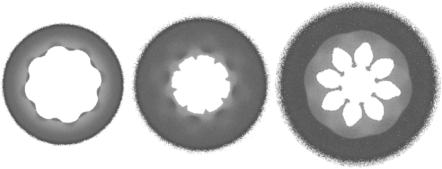

Typical snapshots of MD system in the case of the perturbed converging shock are shown in Figure 1. It is found that for enough large initial perturbation the curved shock front generates Mach stems at very early stage of converging. Then the first generation of Mach stems entails the secondary Mach stems and so on. In fact polygons converge to the center instead of smooth curved shock front. There are -side polygons for mode or -sides at phase inversion stage. Also the Mach stems generate intricate structures of reflected shocks in downstream flow which result in supersonic jets running away from the target boundary. We suppose these jets can amplify instability of ablation front in the real ICF experiments. Figure 2 shows amplitudes of the measured shock front perturbation as a function of a mean shock radius and the perturbation growth rate for different mode numbers. The simulation results show that the perturbations grow if the mode number [4].
Figures 3 and 4 represent simulation results of the RM instability where SW propagates from heavy to light liquids. The typical flow velocity fields are presented in Fig.4. When the shock front hits the interface, the transmitted shock and rarefaction wave are produced and go away from the material interface (Figs. 3,4:left). It is clearly seen that the vorticities are allocated around the material interface and they cause a spike to be formed (Fig.4:right). Fig.3:right shows the RM instability at late simulation time when the total width of the mixing zone goes into the asymptotic stage of the growth.
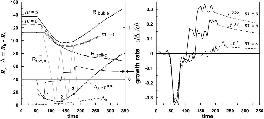
The time history of the RM instability is shown in Figure 5. We measure the thickness of the mixing zone as a distance between the maximum and minimum of interface positions along the radius. For comparison with the symmetrical case we draw mean position (circles) of the cylindrical interface as a function of time. It should be mentioned that small atomic perturbations with even in a pure symmetrical case are unavoidable due to atomistic fluctuations and they begin grow as well as artificial ripples (see in Fig.5 left).
There are three key time points in the RM instability evolution. The first point (1st triangle in the left graph of Fig.5) corresponds to a contact of the shock front with a bottom of the ripple. After that the maximum and minimum are closing in time. The phase inversion occurs at the minimum of , between 1st and 2nd triangles. For the higher mode number the inversion takes place at earlier time than that for the lower mode number. The shock reflected at the origin reaches the interface at the second key time point and it accelerates the growth of the interface perturbations. In the case of mode 5 the coincidence of the phase inversion with the second point occurs accidentally, the phase inversion of the interface for takes place after the secondary reflected shock pushes the interface outward at 3rd key time point, .
Figure 5:right indicates nonlinear evolution of the growth rates for the different modes. Due to numerical differentiation of the thickness of the mixing zone , the growth rate is noisy and we are forced to estimate asymptotical behavior of the growth rate from the differentiation of asymptotic form. In the case of mode 8 the perturbations grow as , and , . Hence the growth rates decay , and , and correspondingly.
3 Conclusion
Molecular dynamics simulation of cylindrical shocks have been performed for the first time. We have demonstrated that MD method is able to catch hydrodynamic instabilities in close details on atomic scale.
It is shown that for a converging cylindrical shock , the compression of Argon liquid is 2.2 at the collapse point, the temperature is around 12000 K, pressure is GPa, converging time ps. The growth rate of a ripples strongly depends on the perturbation modes and slowly decreases in time. Perturbations grow faster for higher mode in the case of the RM instability. Mode 3 ripples grow very slow in comparison with higher mode numbers due to the phase inversion of the interface occurs at very late time.
References
- [1] Y. Yang, Q. Zhang, and D.H. Sharp, Phys.Fluids. 6, 1856 (1994).
- [2] J. R. Kamm, et al., LANL Report LA-UR-99-2783, (1999).
- [3] V. V. Zhakhovskii, S.V. Zybin, K. Nishihara, and S.I. Anisimov, PRL 83, 1175 (1999).
- [4] J. H. Gardner, D.L. Book, and I. B. Bernstein, J.Fluid.Mech. 114, 41 (1982).