Dynamics of nanodroplets on topographically structured substrates
Abstract
Mesoscopic hydrodynamic equations are solved to investigate the dynamics of nanodroplets positioned near a topographic step of the supporting substrate. Our results show that the dynamics depends on the characteristic length scales of the system given by the height of the step and the size of the nanodroplets as well as on the constituting substances of both the nanodroplets and the substrate. The lateral motion of nanodroplets far from the step can be described well in terms of a power law of the distance from the step. In general the direction of the motion depends on the details of the effective laterally varying intermolecular forces. But for nanodroplets positioned far from the step it is solely given by the sign of the Hamaker constant of the system. Moreover, our study reveals that the steps always act as a barrier for transporting liquid droplets from one side of the step to the other.
pacs:
47.61.-k, 68.08.Bc, 68.15.+e1 Introduction
Understanding the wetting behavior of liquids on solid substrates [1, 2] is a prerequisite for making use of a myriad of biological and technological applications such as eye irrigation, cell adhesion, tertiary oil recovery, coating, lubrication, paper industry, micro-mechanical devices, and the production of integrated circuits. Generically, the solid surfaces in the above mentioned examples are not ideal in the sense that they are neither smooth nor homogeneous. Most surfaces are topographically or chemically heterogeneous. Such heterogeneities may substantially change the wetting behavior of these surfaces [3], which is not necessarily detrimental with respect to envisaged applications. Certain topographically structured surfaces are superhydrophobic or superhydrophilic. In the first case droplets roll off these substrates (instead of flowing), such that these surfaces are self-cleaning [4, 5, 6, 7, 8, 9, 10, 11]. In the second case the surface topography leads to a complete spreading of droplets [12, 13, 14]. Tailored topographic surface structures can induce particular dewetting processes which in turn can be exploited to pattern substrates on the micron scale [15, 16].
Microfluidics is another strong driving force for the research on the dynamics of fluids on structured substrates. Shrinking standard laboratory setups to a lab-on-a-chip promises huge cost reduction and speed-up [17, 18]. Open microfluidic systems, i.e., with free liquid-vapor or liquid-liquid interfaces, may provide various advantages such as reduced friction, better accessibility of the reactants, and reduced risk of clogging by solute particles [19, 20, 21, 22]. In open microfluidic devices fluids are guided along chemical channels [3, 23, 24] or in grooves [25], which can be chemically patterned in oder to provide additional functionality [22].
Wetting phenomena on topographically structured substrates have attracted substantial research efforts [25, 26, 27, 28, 29, 30, 31, 32, 33, 34, 35] with, however, the main focus on equilibrium phenomena. In view of the aforementioned applications, dynamical aspects are of particular interest. In spite of this demand, theoretical work on the dynamics of liquid films and droplets on topographically structured substrates has started only recently. In most of these studies the dynamics of the fluids is assumed to be well described by macroscopic hydrodynamic equations, which are solved either directly [36], by a lattice Boltzmann method [37, 38], or in the thin film (lubrication) regime [39, 40, 41, 42]. The applicability of this latter method is limited because the inherent long-wavelength approximation does not keep track of many relevant microscopic features [43].
On the nanoscale, macroscopic hydrodynamic equations turn out to be inadequate for describing the dynamics of fluids. Overcoming this deficit is the focus of a new research area called nanofluidics [44, 45]. Wetting phenomena in particular reveal these deviations; for a recent review of these issues see Ref. [46]. However, hydrodynamic equations can be augmented to include hydrodynamic slip, the finite range of intermolecular interactions, and thermal fluctuations. The resulting mesoscopic hydrodynamic equations have been rather successful in analyzing, e.g., the dynamics of dewetting on homogeneous substrates [47, 48]. The presence of intermolecular interactions can be summarized into the so-called disjoining pressure (DJP), where the effective interface potential is the cost of free energy to maintain a homogeneous wetting film of prescribed thickness . On a homogeneous substrate is independent of lateral coordinates parallel to the substrate surface and the equilibrium wetting film thickness minimizes . However, on chemically or topographically inhomogeneous substrates (structured, rough, or dirty) the generalized disjoining pressure does depend in addition on these lateral coordinates. In most studies, the lateral variations of the disjoining pressure have been modelled rather crudely, i.e., the substrate is assumed to be locally homogeneous and lateral interferences of heterogeneities are neglected: e.g., a step is typically modelled by an abrupt change of the disjoining pressure [49, 50, 51, 52, 53].
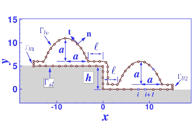
Recently we have demonstrated, that the actually smooth variation of the lateral action of surface heterogeneities can change the behavior of droplets in the vicinity of chemical steps [54, 55] or topographical features (edges and wedges) [56] even qualitatively. In the present study we extend these results to the case of an isolated straight topographic step in an otherwise homogeneous substrate (as shown in Fig. 1) and we recover the previously studied case of isolated wedges and edges in the limit of infinite step height . We should emphasize that our investigation provides only a first but nonetheless essential step towards understanding the dynamics of droplets on arbitrarily structured substrates. Although more refined than previously used models the present one is still rather simple. We only consider additive Lennard-Jones type intermolecular interactions, i.e., we do not take into account electrostatic interactions which would be very important for polar fluids. We assume the fluid to be Newtonian, non-volatile, and incompressible (which is compatible with the frequently used so-called sharp-kink approximation of classical equilibrium density functional theory (see, e.g., Ref. [57]). We also assume a no-slip boundary condition at the solid surface [58] and neglect the influence of thermal fluctuations [59]. For numerical reasons we restrict our investigation to two-dimensional (2D) droplets, corresponding to three-dimensional (3D) liquid ridges (or rivulets) which are translationally invariant in the direction parallel to the step; nonetheless we expect our results to hold qualitatively also for 3D droplets.
2 Summary
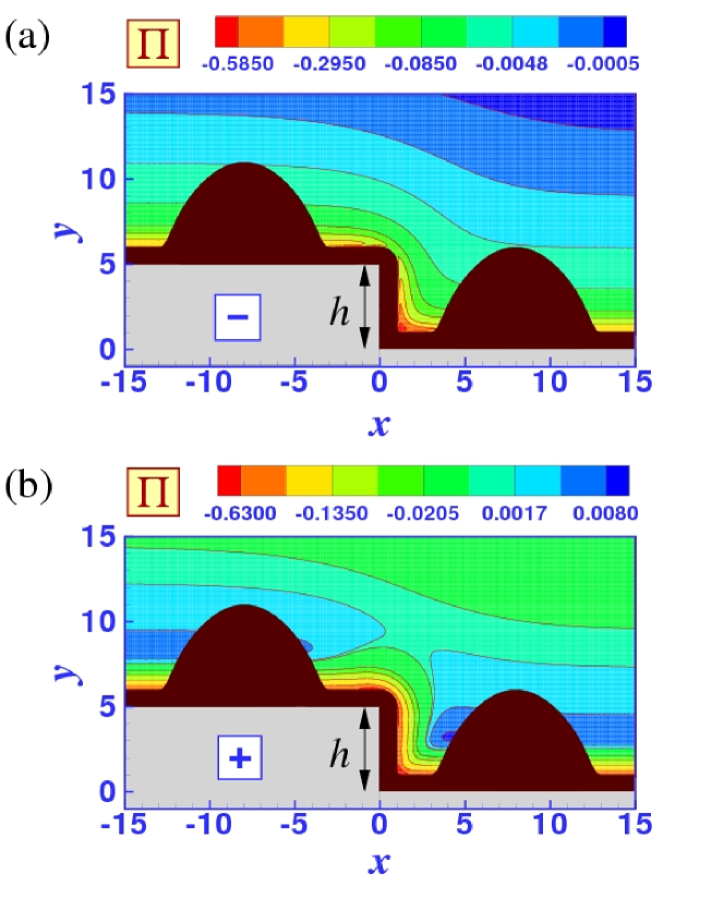
We study the dynamics of non-volatile and Newtonian nanodroplets (corresponding to three-dimensional ridges which are translationally invariant in one lateral direction) on topographically stepped surfaces within the framework of mesoscopic hydrodynamics, i.e., by solving the augmented Stokes equation presented in Sec. 3 with the numerical method described in A. We consider in particular the effects due to the long range of Lennard-Jones type intermolecular interactions which enter the theoretical description in terms of the disjoining pressure (DJP) as illustrated in Fig. 1. We assume the substrate to be chemically homogeneous in the lateral directions and the surface to be covered by a thin layer of a different material. As detailded in Sec. 4 this leads to two adjustable parameters and which enter into the DJP and characterize the wetting properties of the substrate, i.e., the equilibrium contact angle and the wetting film thickness (see Fig. 2). As shown in Fig. 3 both for positive and for negative Hamaker constants one can find a one-parameter family of pairs leading to the same on a flat substrate (i.e., without a step). As shown in Fig. 4 nanodroplets on substrates with the same but with different values of and assume shapes which differ mainly in the vicinity of the three-phase contact line with the apex region is almost unaffected by the substrate potential.
The results of the numerical solution of the mesoscopic hydrodynamic equations are presented in Sec. 5. In contrast to macroscopic expectations based on a capillary model (i.e., taking into account only interface energies and neglecting the long range of the intermolecular interactions), topographic steps do influence droplets in their vicinity: on substrates with a positive Hamaker constant (Figs. 9 and 15), droplets move in uphill direction while on substrates with a negative Hamaker constant (Figs. 5 and 11) the droplets move in the opposite direction. As expected the forces on the droplets and their resulting velocity increase with the step height, but also with the absolute value of the Hamaker constant. This is the case if the contact angle is varied (see, e.g., Figs. 7 and 12) and even if the contact angle is fixed by varying the Hamaker constant and the properties of the coating layer together (see Figs. 8, 10, 13, and 16).
The speed of the droplets increases with their size as demonstrated in Fig. 14. As detailed in Subsec. 6.2, the influence of the step on a droplet can be phrased in terms of an effective wettability gradient, i.e., a spatially varying equilibrium contact angle. The driving force on droplets on such substrates increases linearly with the droplet size because the difference in equilibrium contact angle at the two contact lines of the liquid ridges increases roughly linearly with the distance from the steps.
The velocity of droplets driven away from the step decreases rapidly with the distance from the step as shown in Sec. 6. But droplets moving towards the step (either on the top side or on the bottom side of the step) stop with their leading contact line close to the step edge or wedge, respectively. Therefore they do not cross the step (see Figs. 5, 6, 7, 8, 15, and 16). Accordingly, edges, wedges, and steps act as barriers for migrating droplets (which is also true macroscopically) because droplets sitting right at the tip of an edge are in an free-energetically unfavorable state (see Fig. 17) while droplets located in the corner of a wedge are in a state corresponding to a local minimum of the free energy (see Fig. 20). Therefore, an external force is required to push droplets over edges (see Fig. 18) or to pull them out of wedges (see Fig. 20). In both cases, the total (i.e., integrated over the droplet volume) force required to accomplish this increases slightly with the droplet volume, but less than linearly. This means, that if the force is applied via a body force density acting per unit volume (e.g., gravity) larger droplets experience a larger force and therefore overcome steps more easily. In addition, the lateral action of intermolecular forces can also pin droplets at edges and near wedges. However, droplets which initially span a topographic step always end up filling the wedge at the step base, either with the upper contact line pinned at the step edge or, if the droplet volume is too small, with the upper contact line on the vertical part of the step, as shown in Fig. 19.
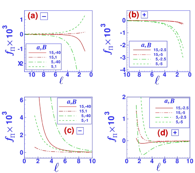
A deeper understanding of the dynamics of droplets in the vicinity of edges and wedges can be reached by analyzing the forces acting on the droplet surface, i.e., the disjoining pressure and surface tension (see Eqs. (6) and (7), respectively). As demonstrated in Fig. 6, if the droplets move under the influence of the topographic step only, the main contribution to the driving force stems from the disjoining pressure. As shown in Figs. 21 and 23, the numerically observed features of the dynamics of droplets can be understood in terms of the disjoining pressure induced force density on the droplets calculated for droplets of simple parabolic shapes used as initial conditions for the numerical solution of the hydrodynamic equations. As shown in Fig. 22 the actual relaxed droplet shape is different but the calculated forces depend only weakly on the deviation of the actual shape from its parabolic approximation. In the limit of large distances from the step the force can be calculated analytically (see Subsec. 6.2): far from the step the total force per unit ridge length (with the cross-sectional area ) essentially depends on the ratio of the step height and the distance from the step as well as on the ratio of the apex height and . The corresponding asymptotic results are summarized in Fig. 24. In all cases the force density varies according to a power law with . For finite sized droplet and steps of finite height we obtain the fastest decay and for almost macroscopic droplets in the vicinity of finite sized steps as well as for nanodroplets near isolated edges and wedges we get . While our present analysis cannot be applied to the case of an almost macroscopic droplet in a wedge, for large drops () next to an isolated edge we get the weakest decay with . In any case, the total force per unit length is proportional to the Hamaker constant as observed in the numerical solution of the mesoscopic Stokes dynamics as well as in the force analysis presented in Subec. 6.1. The dynamics of large drops () is equivalent to the dynamics of macroscopic drops on a surface with an effective chemical wettability gradient (i.e., a spatially varying “equilibrium contact angle” ) [60, 61, 62].
3 Mesoscopic hydrodynamic equations
At low Reynolds numbers the mean field dynamics of an incompressible Newtonian fluid of viscosity is given by the Navier-Stokes equation for the local pressure and the flow field :
| (1) | |||||
| (2) |
with the stress tensor . In this study, we neglect the influence of the vapor phase or air above the film. Therefore the tangential components of the component of the stress tensor normal to the liquid-vapor surface (with outward pointing normal vector ) is zero. The normal component of , i.e., the normal forces acting on the liquid surface, are given by the sum of the Laplace pressure and of the disjoining pressure:
| (3) |
with the surface tension coefficient and the local mean curvature of the liquid surface; is the strength of a spatially constant external body force density pointing in the -direction (with as the corresponding potential) which we introduce in order to study the strength of barriers to the lateral motion of droplets. Alternatively, for incompressible fluids one can define a new pressure such that the external body force density enters into the Stokes equation Eq. (1) rather than the boundary condition in Eq. (3): . Although this approach might be more intuitive, the equivalent form used here is more convenient for implementing the boundary element method used here to numerically solve these equations (see A).
The dynamics of the free liquid surface is determined by mass conservation together with the incompressibility condition: the local normal velocity is identical to the normal component of the local flow field.
We neglect hydrodynamic slip at the liquid-substrate surface and we only consider impermeable substrates. Since we assume the substrate to be stationary this results in the following boundary condition for the flow field:
| (4) |
In order to avoid strong initial shape relaxation of the droplets (in response to placing them on the substrate with a certain shape) which can lead to significant lateral displacements [63], we choose a parabolic initial profile which is smoothly connected to a precursor film of thickness :
| (5) |
such that is the droplet height at the center and half the base width. Accordingly the distance of the droplet edge from the step at is given by with the position of the center of the droplet in the -direction. The parameter specifies the smoothness of the transition region from the drop to the wetting layer. In this study we choose to be . We investigate the droplet dynamics for two different situations. In the first one we position the droplet on the top side of the step of height with the three-phase contact line at a distance with from the step edge at . In the second situation we place the droplet on the bottom side of the step with the three-phase contact line at a distance with from the wedge at the base of the step.
In equilibrium Eq. (3) reduces to the Euler-Lagrange equation of the effective interface Hamiltonian of a fluid film on a substrate as derived, e.g., in Ref. [64]. This means that we approximate the normal forces on the liquid surface due to the intermolecular interactions by the disjoining pressure derived for equilibrium systems.
In a non-equilibrium situation, the unbalanced forces acting on the fluid surface add up to a resulting net force on the liquid body. We separately consider the two contributions and from the disjoining pressure and from the Laplace pressure, respectively, both normalized by the droplet volume and given by the following integrals over the liquid-vapor surface of the droplets:
| (6) | |||||
| (7) |
For a liquid ridge translationally invariant in -direction both integrals as well as are proportional to the macroscopic ridge length , so that the latter drops out of the expressions for the force densities (in units of ) and . In three dimensions is a two-dimensional surface area element. is the two-dimensional cross-sectional area of the liquid ridge.
4 Model of the heterogeneity
In the following we calculate the disjoining pressure for a fluid film or droplet near a topographic step as displayed in Fig. 1. Apart from a very thin coating layer of thickness we assume the substrate material to be homogeneous, disregarding its discrete molecular structure. Many substrates used in experiments are coated, e.g., by a native oxide layer or by a polymer brush which is used to modify the wetting properties of the substrate. However, a more refined analysis of the DJP, which takes the molecular structure of the substrate and of the fluid into account, yields terms of a form similar to those generated by a coating layer [2, 65]. In general, i.e., far from the critical point of the fluid, the vapor or gas phase covering the system has a negligible density which we neglect completely. Assuming pairwise additivity of the intermolecular interactions, i.e., the fluid particles as well as the fluid and the substrate particles are taken to interact with each other via pair potentials where and relate to liquid (), substrate (), or coating () particles and is the interatomic distance, one can show that the disjoining pressure (DJP) of the system is given by [26]
| (8) |
with and and as the number densities of the liquid and substrate, respectively. is the actual substrate volume.
In order to facilitate the calculation of the disjoining pressure of the step we decompose it into contributions from quarter spaces (edges) forming building blocks which can be calculated analytically. We first consider an dge occupying the lower left quarter space , which in the following we denote by . For Lennard-Jones type pair potentials , where and are material parameters, the DJP in the vicinity of a non-coated edge occupying is given by
| (9) |
where and . The first term dominates close to the surface of the edge and the second term at large distances from the substrate.
All integrals in Eq. (9) can be calculated analytically and one obtains the DJP as the corresponding difference of two contributions with
and
| (11) | |||||
The contributions to the disjoining pressure of a thin oating layer of thickness on the pper side of the edge occupying , the ight part of the edge occupying , and the thin rod which fills the ip area of the edge can be calculated analogously:
with and ; stands for (pper), (ight), or (ip). Actual coating layers have a more complicated structure, in particular in the direct vicinity of edges and wedges, which depends on the specific combination of coating and substrate material as well as on the way the coating is produced. Such details can influence droplets if their contact line is right at the edge or wedge but the effect is proportional to the square of the coating layer thickness . For simplicity we only consider systems with coating layers which are thin compared to the wetting film thickness (see below), for which the contribution from the thin rod of coating material at the tip of the edge or in the corner of the wedge is irrelevant. According to Eq. (4) the contribution to the disjoining pressure from the upper coating layer can be decomposed into . To first order in we obtain
| (13) | |||||
and
| (14) | |||||
By symmetry one has for the contribution of the vertical part of the coating. The DJP of a coated edge occupying is therefore given by
| (15) |
The DJP contribution from a coated edge occupying the right quarter space can be obtained analogously. However, since the integrals for the right part corresponding to Eqs. (9) and (4) are the mirror image (with respect to the -plane) of their counterparts for the left hand side, the former ones can be expressed in terms of the latter ones. Therefore the DJP of the coated lower right quarter space is equal to . Combining the contributions of the left and the right part leads to the following expression for the DJP of a step of height :
| (16) |
The last term on the right hand side of Eq. (16) removes the artificial extra coatings on the left and the right quarter spaces (at , ) which get buried upon building the step out of the coated edges. Figure 1 shows typical examples for the DJP. The DJP is not only a function of the vertical distance from the substrate, but also of the lateral distance from the step. In this regard, the substrate in the vicinity of the step resembles a chemically structured substrate with laterally varying wettability [60, 61, 62].
For positions far from the step the distribution of the DJP resembles that of the oated, laterally omogeneous flat substrate obtained by setting in Eq. (16). To linear order in one has
| (17) | |||||
Since the repulsive contributions decay rapidly with distance from the substrate we neglect all those repulsive contributions which are shorter ranged than the corresponding term () arising from [57, 65], leading to
| (18) |
with . The equilibrium thicknesses of the wetting film on such a substrate minimizes the effective interface potential [65, 66]
| (19) |
With Eq. (18) this leads to
| (20) |
The second term is usually written as , where is the so-called Hamaker constant.
At this point we introduce dimensionless quantities (marked by ) such that lengths are measured in units of which for and is the equilibrium wetting film thickness on the uncoated flat substrate. The DJP is measured in units of the ratio where is the liquid-vapor surface tension. Thus the dimensionless DJP far from the edge has the form
| (21) |
In the first and second term of Eq. (21) the upper (lower) sign corresponds to and , respectively. The dimensionless amplitude , with , compares the strength of the effective intermolecular forces in the uncoated case and of the surface tension forces. The amplitude measures the strength of the coating layer. Since the molecular structure of the substrate and of the fluid yields a term of the same form [2, 65] we consider itself as a parameter independent of the actual properties of the coating layer. For the interactions considered here, is a necessary condition for the occurrence of an equilibrium wetting layer of nonzero thickness but can be positive or negative. Therefore the first term in Eq. (21) can only be positive while the second term can be positive or negative. In the following we shall refer to these two cases simply as the minus () and the plus () case. In order to avoid a clumsy notation in the following we also drop the stars. With this, one has
| (22) |
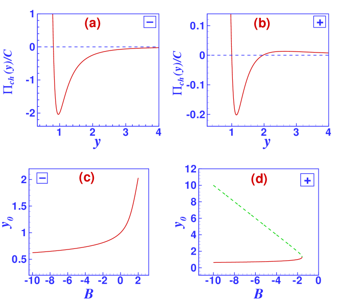
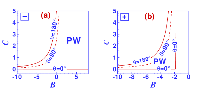
Figure 2 shows the typical profile of for the minus and the plus case and also the corresponding equilibrium wetting layer thickness for which . While the parameter measures the strength of the DJP, by changing one can modify the shape of the DJP [56]. In Eq. (22) the admissible value ranges of and which provide partial wetting can be inferred from considering the equilibrium contact angle [2]:
| (23) |
The admissible value ranges of and for which (partial or incomplete wetting) are given in Fig. 3 for both the minus and the plus case. In the minus case, for each value of one can find a value of such that the resulting substrate is partially wet. Since the signs of the first two terms in Eq. (22) differ the disjoining pressure has a zero for any and the depth of the minimum of the corresponding effective interface potential can be tuned by choosing an appropriate value for . In the plus case, however, has to be negative in order to obtain a sign change of . The maximum admissible value of (i.e., ) can be obtained by simultaneously solving the following equations for and :
| (24) |
| (25) |
from which one finds (compare Fig. 2(d)).
In order to obtain dimensionless hydrodynamic equations (see Eqs. (1)–(3)) we choose as the velocity scale. With this, the dimensionless form of the stess tensor is given by and the surface tension coefficient drops out of Eq. (3). The dimensionless time is given in units of . In order to study the dynamics of nanodroplets we solve the dimensionless hydrodynamic equations with a standard biharmonic boundary integral method described in more detail in A.
5 Results
5.1 Nanodroplets on homogeneous flat substrates
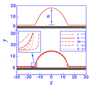
In order to provide the information and terminology required for the subsequent considerations we first recall some basic results for the wetting of flat and homogeneous substrates. For this purpose a nanodroplet with and an initial configuration given by Eq. (5) was positioned on the substrate. Figure 4 shows the equilibrium profile of the nanodroplet for various values of and resulting in an equilibrium contact angle for both the minus and the plus case, i.e., the values lie on the dashed curves in Figs. 3(a) and 3(b). It is evident from the figure that the droplets have relaxed from the initial condition. The equilibrium profiles in all cases are roughly equal but the nanodroplets differ near their contact lines (see the inset of Fig. 4) and with respect to their heights. The term proportional to in Eq. (22) is rather short-ranged and most important in the direct vicinity of the substrate. The top parts of the droplets are only influenced by the term such that the curvature at the peak changes with , independently of . This also changes the droplet height. However, also the wetting film thickness changes with , such that the differences in droplet height in Fig. 4 are a combined result of both effects.
5.2 Nanodroplets on the top side of steps
Previous studies of droplets near edges (corresponding to steps of infinite height) have shown that, in contrast to what is expected from a simple macroscopic model taking into account only interface energies, droplets are attracted towards the edge in the minus case and repelled from the edge in the plus case [56]. In the minus case, the droplets move towards the edge with increasing velocity, but they stop rather abruptly before the leading contact line reaches the edge. The distance from the edge at which the droplets stop increases with decreasing , i.e., with increasing strength of the coating layer. In the plus case, the droplets move away from the step with a velocity which decreases with the distance from the step. The strength of the attraction or repulsion is expected to be lower for steps of finite height.
5.2.1 Minus case
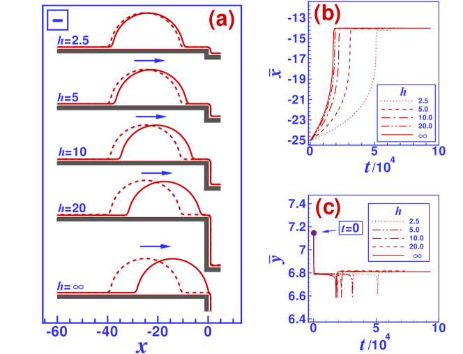
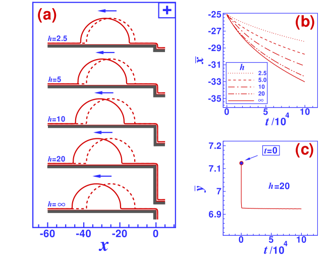
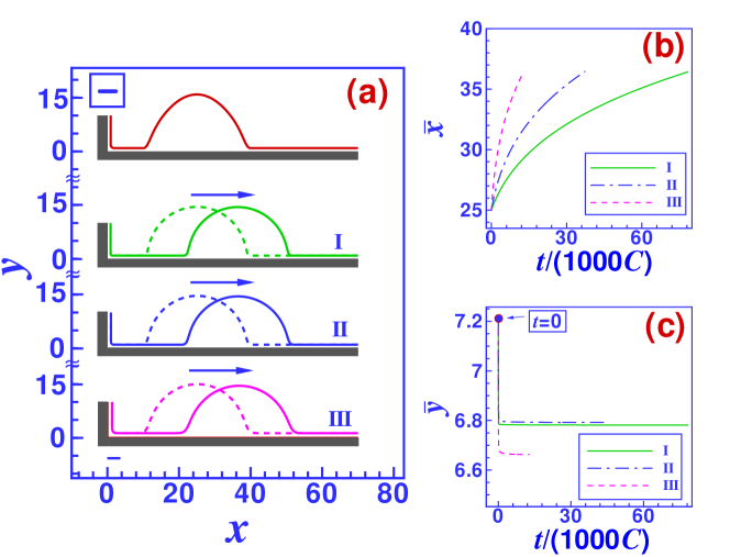
In order to test the influence of the step height on the dynamics of nanodroplets identical droplets of half base width were placed at a distance from steps of height 2.5, 5, 10, 15, 20, and . The results of the numerical solution of the mesoscopic hydrodynamic equations for the minus case are shown in Fig. 5(a) for and which corresponds to . In order to have a better view on the dynamics we monitor the time evolution of the position of the center of mass of the droplets (, ) relative to the step edge in Figs. 5(b) and 5(c), where and are given by
| (26) |
with denoting the droplet volume. Since the droplets are smoothly connected to the wetting film, which on large substrates would influence the center of mass of the fluid, in calculating and we only consider the fluid above with , i.e., only the fluid volume slightly above the wetting film. We selected ; but since we focus on substrates with equilibrium contact angles of about the results are only weakly affected by the precise choice of the value of .
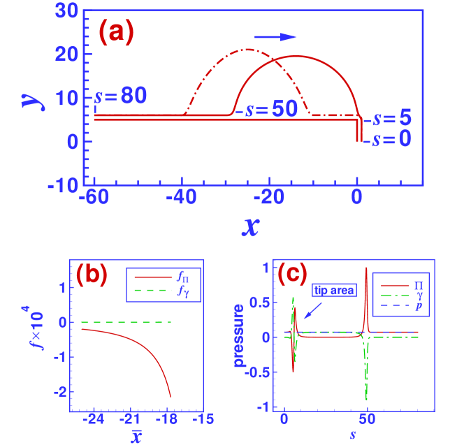
In all cases the dynamics of the droplets proceeds in three stages. The first stage is a fast initial shape relaxation, similar to the behavior on homogeneous substrates, which is accompanied by a lowering of the droplet center of mass without any considerable lateral motion. This is followed by a relatively slow lateral motion towards the edge, during which the changes in the droplet shape are almost unnoticeable. Although the droplet shape is slightly asymmetric the lateral surface tension induced force density defined in Eq. (7) is much smaller than the force density induced by the DJP (see Eq. (6)) as shown in Figs. 6(b). Figure 5(b) clearly shows that the lateral motion of the droplet slows down rapidly as soon as its leading three phase contact line reaches the edge. During this third and final stage a part of the droplet volume leaks into the wetting film on the vertical part of the step and as a result the droplet experiences a sudden drop in its height (see Fig. 5(c)). The trailing three-phase contact line of the droplet still continues its motion towards the step and as a consequence the mean height of the droplet increases again and becomes even larger than during the migration stage. While the droplet contracts, its asymmetry gradually increases such that the surface tension induced force density grows and finally, as the equilibrium configuration is reached, cancels . (This latter stage of cancelation is not visualized in Fig. 6(b) due to numerical problems in evaluating the force densities on droplets once they have reached the step edge.) In equilibrium, at each point on its surface the Laplace pressure and the disjoining pressure ad up to the constant value of the hydrostatic pressure in the droplet (see Fig. 6(c)).
Increasing the step height from to 5 and 10 results in a significant increase in the droplet speed during the migration phase. The asymptotic speed for isolated edges (corresponding to ), i.e., the maximum speed, is almost reached for . This height value is large compared to the thickness of the wetting layer but comparable with the droplet size; here the base diameter is . However, in order to be able to conclude that the step height above which the droplet perceives the step as an isolated edge is comparable with the droplet size further calculations for droplets of different size are needed.
Changing the equilibrium contact angle by increasing while keeping does not qualitatively change the behavior of the droplets, as shown in Fig. 7(a) for droplets with near an isolated edge (corresponding to ), apart from the increase of during the initial relaxation process for large . The reason for this increase in droplet height is, that the initial shape of the droplet is not adapted to the substrate parameters. Changing does not change the functional form of the DJP, only its strength. Consequently, droplets move faster for larger (resulting in larger ) and their final shape is less symmetric. With the leading contact line pinned right at the step edge, large also result in an overhang over the step edge. Since for fixed wetting film thickness on the uncoated flat substrate the time scale used to obtain dimensionless hydrodynamic equations depends on the substrate parameters in the same manner as the dimensionless parameter , we rescale time by in Figs. 7(b) and 7(c), as well as in all subsequent figures which compare and for different values of . This corresponds to changing the substrate material but keeping surface tension, viscosity, and wetting film thickness constant [54].
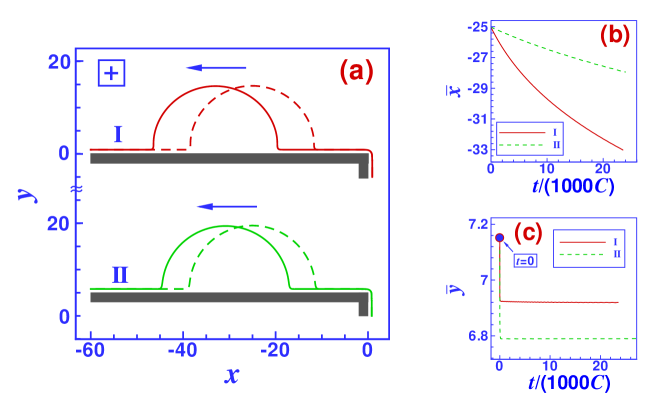
Figure 8(a) shows the effect of changing the value of (while keeping the contact angle constant) on the dynamics and on the final configuration of droplets which start with and for the minus case on the top side of an isolated edge (). For each value of we choose such that , i.e., corresponding to the dashed curve in Fig. 3(a). For all values of the droplets move towards the edge. Changing the values of and does not qualitatively change the behavior of the system. However, a closer examination of and (see Figs. 8(b) and 8(c), respectively) reveals quantitative differences in the dynamics and in the final configuration of the droplets despite the fact that the contact angle is the same for all these cases. For larger (positive) values of (and thus , see Fig. (3)(a)) droplets move faster in lateral direction although the contact angle equals for all of them. In addition, the final position of the droplets is closer to the step edge for larger values of , eventually leading to a slight overhang. The small differences in for different values of is related to the fact that the shape of nanodroplets is not only determined by , as shown in Fig. 4, and that the wetting film thickness depends on .
5.2.2 Plus case
Even if they exhibit the same equal equilibrium contact angles the behavior of droplets in the plus case differs substantially from that in the minus case: the direction of motion is reversed. However, apart from this sign change, the influences of the step height, the equilibrium contact angle, and are similar.
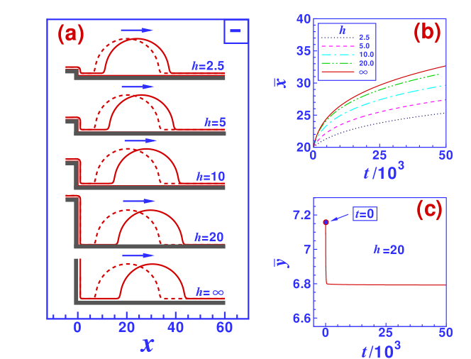
The dependence of the droplet dynamics on the step height for the plus case is shown in Fig. 9(a). The initial size of the droplets is and the contact angle (with , ). The corresponding lateral and vertical positions of the center of mass of the droplets relative to the step edge are shown in Figs. 9(b) and 9(c), respectively. As in the minus case the migration phase is preceded by a fast initial relaxation process (during which drops slightly). However, the droplets are repelled from the step. The lateral speed of the motion continuously decreases as the distance of the droplets from the step edge increases. For higher steps the droplets are faster. But as in the minus case, the maximum speed (reached for , i.e., in the case of an isolated edge) is almost reached for (see Fig. 9(b)).
The results for different values of , while keeping the contact angle fixed, are depicted in Fig. 10(a). The corresponding lateral and vertical positions of the center of mass of the droplet relative to the step edge are given in Figs. 10(b) and 10(c), respectively. For all the cases considered the droplets move away from the step. However, as in the minus case, the droplet speed increases with (i.e., for less negative values of ), even though the contact angle is not changed. The reason for this is, that larger (i.e., less negative) values of require larger values of in order to maintain the same . As in the minus case the droplet height, i.e., , depends on as well.
5.3 Nanodroplets at the step base
In Ref. [56] we have demonstrated that droplets near corners, i.e., at the base of a step of infinite height, are attracted to the corner in the plus case and repelled from the corner in the minus case (while in a macroscopic model taking into account only interface energies the free energy of the droplets is independent of their distance from the corner). In other words, the direction of motion is reversed as compared to the case of the edge. However, as we shall show in the following, at a step composed of an edge and a corner at its base, the direction of motion of nanodroplets is the same on both sides of the step.
5.3.1 Minus case
As in the case of droplets on the top side of steps, the step height influences the droplet velocity but not the direction of motion and the transition from a planar substrate () to an isolated wedge () is continuous. This is demonstrated in Fig. 11 for droplets of size starting at a distance from the corner. The initial distance is chosen such that after the initial relaxation which precedes the migration phase the contact line facing the corner is well separated from the wetting layer on the vertical part of the step. For the minus case Fig. 11(a) presents the results of our Stokes dynamics calculations for droplets at the step base for different step heights. The droplets are repelled from the step and move away with a speed which decreases continuously with the distance from the step. The differences in droplet speed are significant between step heights , 5, and 10 (see Fig. 11(b)). Increasing the step height further influences the dynamics of the droplets only at large distances from the step.
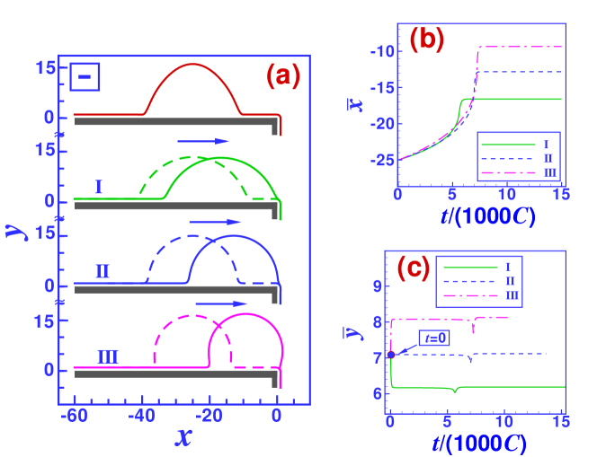
Changing the equilibrium contact angle does not change the droplet dynamics qualitatively. This is demonstrated in Fig. 12(a) for droplets on substrates with different values of (while keeping ). The top panel shows the initial shape used in all cases considered here for the numerical solution of the Stokes dynamics. The corresponding lateral position and vertical position of the center of mass of the droplets relative to the corner are depicted in Figs. 12(b) and 12(c), respectively. Increasing (by increasing ) results in faster droplet motion. Since the initial droplet shape is not adapted to the modified contact angle , changes rapidly during the initial relaxation process for .
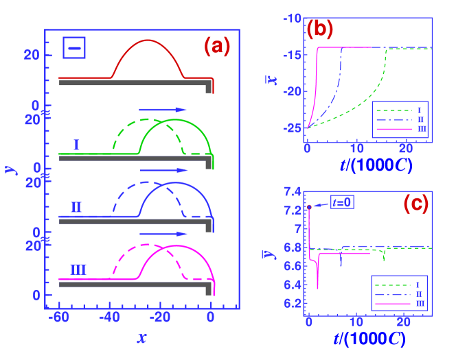
The dynamics of droplets on substrates with the same contact angle but different values of (with adapted accordingly) is shown in Fig. 13(a). The top panel shows the initial configuration. For all cases considered the droplets move away from the step. Comparing for different values of (see Fig. 13(b)) shows, that the droplet velocity increases with (which, for fixed , implies increasing ). After the initial relaxation process the vertical coordinate of the center of mass does not vary in time (see Fig. 13(c)).
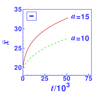
The droplet dynamics depends on the droplet size. This is demonstrated in Fig. 14 for droplets of initial sizes and starting at near an isolated wedge for the minus case. The larger droplet moves faster because its two three-phase contact lines have a larger lateral distance from each other such that they experience a larger difference in the local disjoining pressure.
5.3.2 Plus case
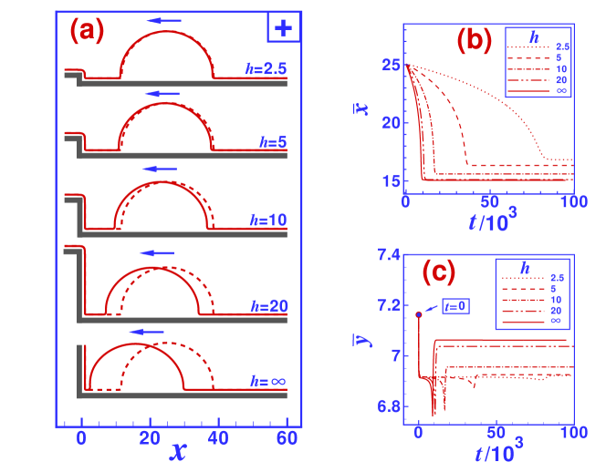
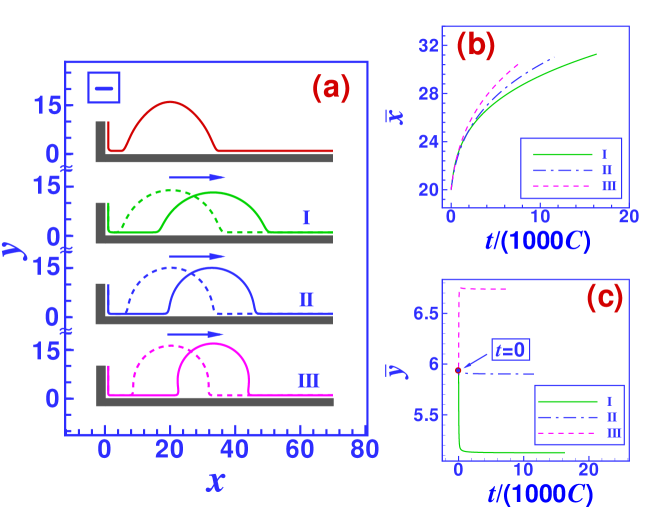
In the plus case the direction of motion of the droplets is reversed as compared to the minus case. As shown in Fig. 15(a), the migration speed increases with the step height, but the droplets stop before the leading contact line reaches the wedge such that the droplets do not move into the corner. As in the other cases discussed so far, the droplet speed increases significantly as the step height is increased up to . In Fig. 15(b) the trajectories for and for almost coincide. The final distance of the droplets from the wedge decreases with the step height, but it remains finite in the limit . Once the droplets reach the wedge there is a brief drop of due to fluid leaking out of the droplet into the corner area. After that their vertical position of the center of mass increases again (see Fig. 15(c)). This increase is the result of a contraction of the droplets, which is also observed for droplets on the top side of steps in the minus case and which is more pronounced for higher steps.
Changing and such that remains the same does not change the dynamics of the droplets qualitatively. Higher values of and result in larger droplet velocities (see Fig. 16 concerning the example of droplets near an isolated wedge). Beside this change of droplet speed we find that for larger values of the final position of the droplets is closer to the step and the final height of their center of mass is larger. The magnitude of the disjoining pressure and therefore the forces acting on the droplet increase with . In response to these forces the droplets deform more upon increasing .
5.4 Nanodroplets on edges, wedges, and steps
In the previous subsections we have discussed the behavior of nanodroplets originally positioned at a certain lateral distance from topographic features such as edges, wedges, and steps. Their behavior suggests that these surface features provide migration barriers for droplets. Even in those situations in which droplets migrate towards the edge or wedge, respectively, they stop just before reaching them. This result is also borne out in a macroscopic model which takes into account only interface energies: the free energy of a droplet positioned right on an edge is larger than that of a droplet of equal volume residing on a flat and homogeneous substrate, and the free energy of a drop in the corner of a wedge is even lower. As a consequence, we expect that droplets sitting on edges to be in an unstable and droplets sitting inside the corner of a wedge to be in a stable configuration. Moving, by force, a droplet (with the shape of the liquid-vapor interface remaining a part of a circle) in the first case slightly to one side results in an increased contact angle on this side, while the contact angle on the other side decreases. However, with the leading contact angle being larger than the equilibrium one the corresponding contact line will move away from the edge, while the trailing contact line (with the corresponding contact angle being smaller than the equilibrium one) moves towards the edge. As a consequence, the droplet leaves its position at the edge. In the case of a droplet in a wedge, the situation is reversed: moving, by force, the droplet into one direction results in a decreased contact angle on this side and an increased contact angle at the trailing side, such that the droplet moves back into the corner of the wedge. Accordingly one expects that a certain force has to be applied to push a droplet over an edge or to pull it out of the corner of a wedge. In the following our detailed numerical results indicate that this also holds for nanodroplets and they enable us to quantify those external forces.
Our analyses show that a nanodroplet positioned symmetrically on the tip of an edge is unstable on all types of substrates, regardless of whether the droplets migrate towards the edge or away from the edge (see Fig. 17; there a suitable, highly symmetric initial shape of the liquid-vapor interface has been chosen such that it indeed relaxes to the unstable state of a droplet sitting on the tip of the edge). Due to the mirror symmetry with respect to the diagonal of the edge, a droplet right at the tip of an isolated edge is in mechanical equilibrium but in an unstable one. In the minus case, after a small perturbation the droplet flips either up or down but then rests next to the step, i.e., in the position which it would assumes upon migrating towards the edge (Fig. 17(a)). In the plus case, as expected from the previous results the droplet migrates away from the edge after flipping to either side (Fig. 17(b)). At steps of finite height, this symmetry is broken by the presence of the wedge. In the minus case, the droplets are pushed away from the wedge, i.e., upwards, which is consistent with the dynamics of droplets in the vicinity of isolated wedges of the same material. However, being attracted to the edge as shown in the previous subsections, they come to rest with the trailing contact line pinned to the step edge (Fig. 17(c)). In the plus case the droplets move in the opposite direction, i.e., they are attracted by the wedge which they migrate to after leaving the edge area (Fig. 17(d)).
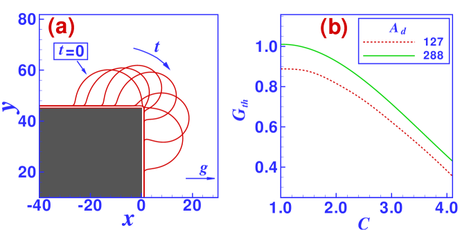
In order to displace a droplet from one side of an edge to the other side (as shown in Fig. 18(a)) one has to apply an external force, e.g., a body force such as gravity or centrifugal forces, which we incorporate into the hydrodynamic equations via the boundary condition (see Eq. (3)). If the applied force is small the droplets assume a new but distorted equilibrium position with the leading three-phase contact line still pinned at the edge. But there exists a threshold force density beyond which the configuration described above is unstable and the leading three-phase contact line depins from the step edge. As a consequence the droplet flips around the corner and ends up on the vertical side of the edge. Since the applied body force has no component parallel to this vertical part of the substrate, the further fate of the droplet is determined by the action of the intermolecular forces. In the minus case considered in Fig. 18(a) the droplet is attracted to the edge such that the new stable equilibrium configuration is that of a droplet residing on the vertical part of the step with the trailing three-phase contact line pinned at the step edge. In the plus case (which we have not tested numerically) the droplet is repelled from the edge and it is expected to move down the vertical part of the edge. As shown in Fig. 18(b) we have determined the body force density needed to push the droplets over the edge for various types of substrates (minus case with ) and for droplets of two different sizes. The threshold force density decreases both with (i.e., with ) and with the droplet size. Both trends are also expected to occur for macroscopic droplets. In the limit the droplets loose contact with the substrate and the free energy of the droplet at the edge equals the free energy on a planar substrate. Taking, however, the finite range of molecular interactions into account this no longer holds, but the barrier still decreases with increasing . Since the force density is a body force, i.e., a force density, the total force per unit ridge length (with the ridge cross-sectional area ) acting on the droplet is proportional to the droplet cross-sectional area . In Fig. 18(b) we observe that the total threshold force needed to push droplets over the edge increases with the droplet volume. Apart from the effects of long-ranged intermolecular forces the main contribution to the barrier effect of the edge is the increase of the liquid-vapor surface area when the droplet is deformed as it passes over the edge. The square root of the ratio of the surface tension coefficient and the body force density defines a capillary length below which the surface tension dominates, while it is less important for larger drops. (The surface area of three-dimensional droplets increases only quadratically with the droplet radius while the volume increases .) From dimensional arguments one expects the threshold body force density needed to push droplets over an edge to decrease with the droplet radius, while for liquid ridges the total force per unit length should still increase linearly with the droplet radius . Therefore the total threshold force needed for the larger droplet in Fig. 18(b) should be about times the force needed for the smaller drop. The actual value is somewhat smaller and we attribute the difference to the effect of the long-ranged part of the intermolecular forces.
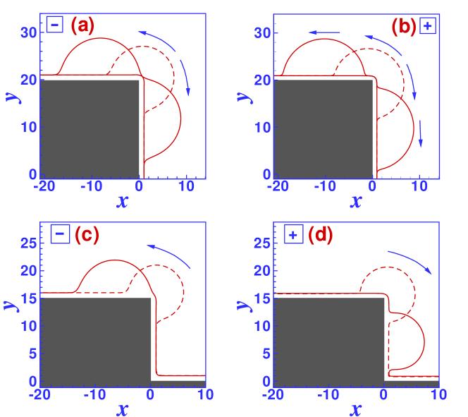
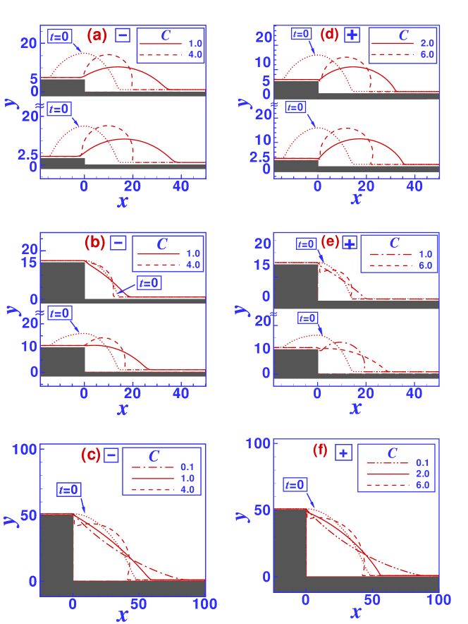
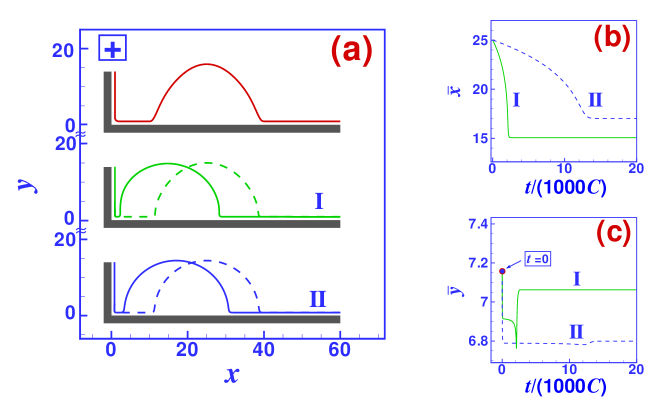
A macroscopic droplet spanning the whole topographic step (i.e., with one contact line on the top terrace and one on the base terrace) moves downhill: since the surface of a macroscopic droplet is a part of a circle which is cut by the top side of the step at a higher level than by the base of the step the contact angle at the upper terrace is smaller than the contact angle at the lower terrace. This results in a net driving force in downhill direction. The final configuration is a droplet with the upper contact line pinned at the step edge. This is also true on the nano scale, as demonstrated in Figs. 19(a) and 19(b) for the minus case and in Figs. 19(d) and 19(e) for the plus case. The latter indicates that the difference in contact angle at the two contact lines due to the different height level at the top side and at the base side of the step provides a stronger driving force than the lateral action of the disjoining pressure which, in the plus case, moves droplets positioned next to the step in uphill direction.
For all substrates the surface of droplets pinned at the edge becomes convex (corresponding to a negative pressure in the droplet) for small (i.e., small , see in Figs. 19(c) and 19(f)). For very large the upper contact line depins from the edge and moves down towards the wedge (see in Figs. 19(c) and 19(f)). The result is a droplet sitting in the corner of the wedge area only. The critical value for between both types of configurations depends on the droplet volume and the step height: the smaller the droplet (as compared to the step height) the smaller is the value of at which the upper contact line depins and the larger the volume the smaller is the value of at which the droplet surface becomes convex. Both phenomena are in qualitative agreement with macroscopic considerations which take into account interface energies only (see Refs. [25, 68]).
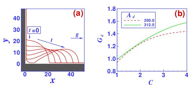
Droplets sitting in the corner of a wedge are in an energetically rather favorable situation as illustrated by the arguments given at the beginning of this subsection. However, even in the plus case, for which droplets are attracted by wedges, they stop before reaching the wedge and they do not move into the corner of the wedge. In any case, there is an energy barrier to overcome in order to move droplets out of wedges, as shown in Fig. 20(a). If a small horizontal force is applied to a droplet sitting in the corner of a wedge it assumes a new, slightly distorted but stable shape. But there exists a threshold force density above which the distorted configuration becomes unstable and the droplet moves out of the corner. In the minus case considered in Fig. 20, the droplet is repelled from the wedge such that the effect of the intermolecular forces adds to the external driving force and the droplet definitively moves out of the corner of the wedge. In contrast to the force required to push droplets over an edge, increases with (i.e., with ). The total force per unit ridge length required to pull a droplet out of a wedge increases only slightly (i.e., less than linearly) with the droplet volume (see Fig. 20(b)), so that accordingly the required force density decreases significantly with volume. With the same dimensional arguments used above for droplets being pushed over edges one would expect the total force needed to pull two droplets of different volume out of the corner of a wedge to be proportional to the square root of the volume ratio. In particular for small according to Fig. 20(b) the total threshold force is almost independent of the droplet size, rather than to increase by a factor . We attribute this difference to the influence of the long-ranged part of the intermolecular forces.
6 Discussion
6.1 Force analysis
Numerical solutions of the Stokes dynamics of nanodroplets in the vicinity of edges, wedges, and steps are rather time consuming, even when using advanced numerical methods. As shown in Fig. 6(b), the main driving force for the migration of droplets is the disjoining pressure induced force density as defined in Eq. (6). After the initial relaxation process, the shapes of the droplets hardly change during the migration process until the droplets either reach the edge (minus case) or the corner of the wedge area (plus case). Unfortunately the relaxed shape of the droplet is not available analytically, but for droplets on substrates with as mostly considered here the initial shape relaxations are rather mild. Accordingly, as demonstrated in the following, the force on the droplets can be estimated rather accurately from calculating for droplets with a shape given by the initial profile in Eq. (5) positioned at the distance from the edge or from the corner of the wedge. Apparently this estimate becomes invalid for .
Figures 21(a) and 21(b) show the disjoining pressure induced force densities calculated along these lines for droplets of size and as a function of the distance of the right contact line to an edge for the minus and the plus case, respectively. Since is proportional to only results for are shown. For the plus case the force is always negative for both droplet sizes and at all distances from the edge, with its strength increasing towards the edge. This means that droplets should move away from the edge with a speed which decreases continuously. This is in complete agreement with the numerical results presented in the previous section. For the minus case and for sufficiently large values of , the force is positive in accordance with the numerical results. However, as shown in Fig. 21(a), for very small values of , i.e., for the force in the direct vicinity of the edge becomes negative and droplets are expected to move away from the edge. Indeed, as demonstrated in Fig. 8(b) ( for I lies below the corresponding values for II and III), the final distance of the droplets from the step edge in the minus case increases with more negative values of . On the other hand, as shown in the following Subsec. 6.2, for large distances from the edge, in the minus case even for arbitrarily small the force is positive so that droplets find an equilibrium position with vanishing force at a significant distance from the edge. The sign of the disjoining pressure induced force density does not depend on the droplet size. However, the equilibrium position changes as a function of droplet size.
The force calculated for droplets of the same size but in the vicinity of a wedge for the minus and the plus case are shown in Figs. 21(c) and 21(d), respectively. For the minus case the force is positive for any droplet size and for any , which means that the droplets move away from the wedge. For the plus case the force is negative at large distances, but it changes sign close to the wedge at a distance which increases with decreasing the size of the droplets and with decreasing the value of . The latter relation is in agreement with the numerical results presented in Fig. 16(b).
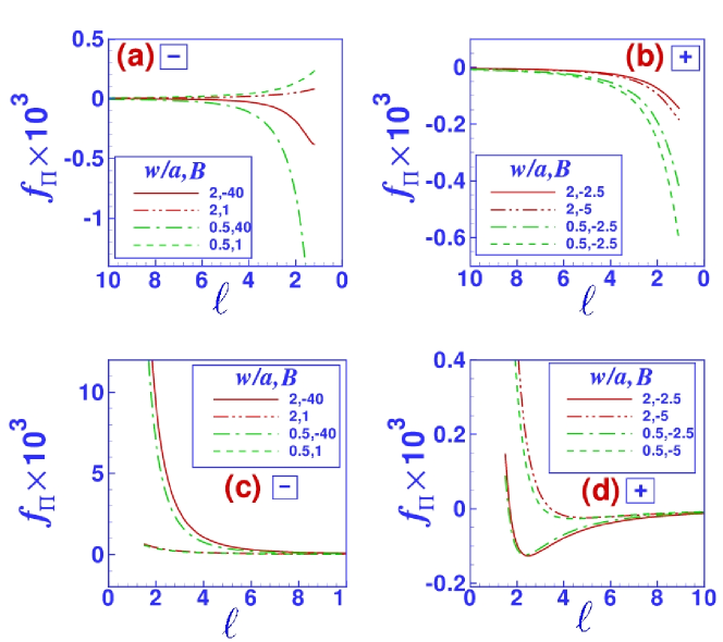
The disjoining pressure induced force density presented in Fig. 21 has beeen calculated for droplets with a shape given by Eq. (5), i.e., for droplets with equal height and half width. However, the substrate parameters used in Fig. 21 do not necessarily lead to , and droplets would adopt a very different shape even during the migration process. In order to check the influence of the droplet shape on the calculated disjoining pressure induced force density we also consider droplets which have a width different from their height (compare with Eq. (5)):
| (27) |
Figure 22 compares the disjoining pressure induced force density on droplets in the vicinity of edges and wedges in both the minus and the plus case for different drop widths but for a fixed drop height . The results indicate that the form of the droplets does not change the sign of , and in particular in the vicinity of the wedge the droplet width has a rather small influence on the force.
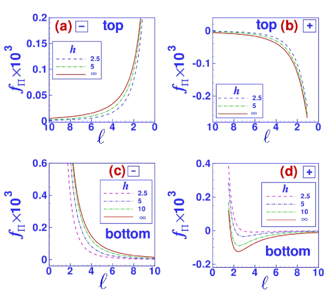
In the vicinity of topographic steps the dependence of on the step height is also in good agreement with the results of the full numerical solution of the Stokes dynamics. Figure 23 shows above and below the step on substrates of the minus and plus type for step heights ranging from to (i.e., to isolated edges and wedges). The absolute value of the force increases with the step height with the force near isolated edges and wedges as the limiting values. This limiting value is almost reached for a step height (not shown in Fig. 23).
6.2 Direction of motion far from the step
Both the force calculations presented in the previous subsection as well as the results of the numerical solution of the mesoscopic hydrodynamic equations indicate, that the direction of motion of a nanodroplet far enough from the step does not depend on whether the droplet is positioned on the top side or on the bottom side of the step. In the minus case the droplets move in downhill direction (i.e., in the direction of positive -values) and in the plus case in the opposite direction, independent of the step height and of the values of and (where the latter has to be positive). In order to understand this we further analyze the total force per unit ridge length on liquid ridges as defined in Eq. (6) for large droplets far from the step. Asymptotically for large the DJP reduces to its value on a flat substrate so that there the wetting film thickness assumes its value independent of up to . The leading order correction to the DJP is for the plus and minus case, respectively. Parameterizing the shape of the liquid-vapor interface to the left and to the right of the droplet apex by and , respectively, from Eq. (6) with we obtain:
| (28) | |||||
with the droplet apex height . In the last but one step we have approximated with . The force is proportional to the droplet cross-sectional area and its sign is determined by the sign of the Hamaker constant (i.e., depending on the case; plus or minus) only: in the plus case the force is negative (upper sign) and in the minus case it is positive (lower sign). This is in complete agreement with the numerical data. However, other than suggested by Eq. (28), the force on a droplet does not diverge in the limit as this limit has to be taken before taking the limit .
At large distances from an isolated wedge as well as from an isolated edge, the disjoining pressure is to leading order given by the DJP of the corresponding homogeneous substrate with as the leading order correction for the plus and the minus case, respectively. As in the case of the step, up to this order the thickness of the wetting film is independent of the (large) distances from the edge or wedge. Using the same approximations as in the case of the step of finite height, the force on a droplet at a distance from an edge is given by
| (29) |
with the upper sign corresponding to the plus case and the lower sign to the minus case. The sign of the force is the same as in the case of a step and it is also proportional to the droplet volume. However, it decreases less rapidly with the distance from the step.
For very large, almost macroscopic droplets, the situation is again different from the previous two. In the following we follow the line of arguments developed in Refs. [54, 55] for droplets in the vicinity of chemical steps. In this limit the droplets are approximately symmetric with respect to their apex and the main contribution to the force stems from the vicinity of the contact lines. For the wetting film as well as near the apex the -component of the surface normal vector is zero and thus in the vicinity of the apex the DJP is negligibly small. In most of the examples discussed here the equilibrium contact angle is about and, as a consequence, the lateral width of the contact lines (i.e., the range of -values within which the drop profile crosses over to the flat one of the wetting film) is small and the lateral variation of the DJP within this region is negligible. Therefore, after parameterizing the droplet surface in the vicinity of the left and right contact line (at and , respectively) by the corresponding function , the total force on a droplet can be approximated by
| (30) | |||||
where is the local effective interface potential at the level of the wetting film (on the top side of the step one has to add to ). Extending Eq. (23) to inhomogeneous substrates one can define a spatially varying “equilibrium contact angle” . In this sense, a droplet in the vicinity of a topographic step is exposed to an effective chemical wettability gradient which it follows. Expanding for large yields
| (31) |
with the upper sign corresponding to the plus case and the lower sign to the minus case. The force is equal on both sides of the step and it increases linearly with the step height but it decreases rather rapidly with the distance from the step, however, more slowly than in the case of nanodroplets. The force increases linearly with the base width rather than with the cross-sectional area . As in the case of nanodroplets the actual force on a droplet does not diverge in the limit . Using the same approximations as in the case of the step of finite height, the force on a droplet at a distance from an isolated edge is given by
| (32) |
with the upper sign corresponding to the plus case and the lower sign to the minus case. In the vicinity of a wedge the situation is more complicated. In order to obtain as in Eq. (30) the effective interface potential, the point corresponding to the upper limit of the integral there has to correspond to a point at infinite distance from the substrate. However, taking to for a fixed value does not change the distance from the vertical part of the wedge. At this point it is not clear whether the force integral in Eq. (6) can be approximated by the form given in Eq. (30) because the basic assumption, that the disjoining pressure is negligible at the apex, is probably not true. Expanding the force as calculated from Eq. (30) for large distances from a step of very large height one obtains terms of the order competing with terms of order , which indicates that in the case of a wedge the approximations Eq. (30) is based on lead to a mathematically ill-posed problem.
In all cases essentially depends on the ratio of the step height and the distance from the step as well as on the ratio of the apex height and . The asymptotic results are summarized in Fig. 24. varies according to a power law , , of the distance from the step. For finite sized droplet and steps of finite height ( and ) we obtain the fastest decay with . For almost macroscopic droplets () in the vicinity of finite sized steps and for nanodroplets near isolated edges and wedges one has . For large drops () next to an isolated edge we get the weakest decay with . In any case, the total force per unit length is proportional to the Hamaker constant as observed in the numerical solution of the mesoscopic Stokes dynamics as well as in the force analysis presented in Subec. 6.1.

6.3 Estimates for the velocity
The driving force on the droplets is balanced by viscous forces. By applying a simple analysis within the lubrication approximation one can show that the rate of energy dissipation is proportional to the square of the velocity of the droplets [1, 69]. The form of this dependence can be expected to hold also for droplets with large contact angles on the basis of analyticity and symmetry arguments. By equating this dissipation with the work done by the driving force one finds
| (33) |
For droplets far from the step with given by Eqs. (31) and (32) as a power law one has and therefore
| (34) |
with for large droplets in the vicinity of edges, for large droplets in the vicinity of steps of finite height as well as for nanodroplets near isolated edges and wedges, and for nanodroplets near steps of finite height. is a constant which also depends on whether there is an edge, wedge, or a step and whether the droplet is large or small. The functional form given by Eq. (34) with the corresponding value of can be fitted to the positions of nanodroplets as a function of time obtained by numerically solving the mesoscopic hydrodynamic equations, e.g., to the data shown in Fig. 9 (droplet on the top side of steps, plus case) and Fig. 11 (droplet on the step base, minus case). However, the numerically available range of values is rather small so that the fits are consistent with the above values of but cannot rule out different ones. In addition, it is not clear whether the distances considered in the numerical solutions of the mesoscopic hydrodynamic equations are large enough to reach the asymptotic regime considered here, and whether the droplets should be considered small or large in the above sense.
7 Perspectives
A major and obvious driving force for studying the dynamics of nanodroplets on structured substrates is the rapid development and miniaturization of microfluidic devices, in particular of open microfluidic devices [19, 20, 21, 22]. But this is not the only research area for which a detailed understanding of the influence of the long-ranged part of the intermolecular interactions on fluids in the vicinity of lateral surface structures might be important. Another example is the dynamics of nanodroplets at chemical surface structures as discussed in Refs. [54, 55]. Moreover, dewetting processes are also strongly influenced by surface heterogeneities, both during the initial phase of film breakup [16, 70] as well as during hole growth [33]. The latter example is particularly interesting in this respect because it reveals an intrinsic nanoscopic length scale which has to be understood: the receding contact line is pinned only by steps of a minimum height which increases with the size of the liquid molecules [33]—a clear indication that details of the intermolecular interactions in the vicinity of the step are relevant.
All results presented in this article have been obtained for homogeneous straight liquid ridges. Apart from the fact that such ridges are unstable with respect to breaking up into three-dimensional droplets [71, 72, 23, 24], the question remains to check how relevant these results are for actual three-dimensional droplets. In this context we point out that the basic driving mechanism for droplets in the vicinity of steps is the difference of the disjoining pressure on that side of the droplet which is closer to the step and the side which is further away from the step. In such a situation also three-dimensional droplets move. However, the third dimension certainly changes the behavior of droplets spanning topographic steps [73, 74]: depending on the droplet volume, the droplet can spread along the step into a cigar shaped configuration. The influence of the long-ranged part of the intermolecular interactions on this phenomenon has not yet been studied.
It is worthwhile to point out that, although the dynamics is different, there are strong similarities between nanodroplets and solid nanoclusters: their energetics on structured surfaces is determined by intermolecular forces as demonstrated in Ref. [75] by molecular dynamics simulations of gold clusters on graphite surfaces. Unfortunately, in such simulations taking into account the long-ranged component of the intermolecular forces increases the numerical cost drastically, such that most of the effects discussed here are not accessible by molecular dynamics simulations [76].
This leaves the question of experimental tests of our theoretical predictions presented here. As detailed in Ref. [56] the forces on the nanodroplets are of the order of N (i.e., about eight orders of magnitude stronger than the gravitational force on such a droplet) and the resulting velocities range between and for viscosities between and . While topographic surface structures of almost any type can be produced with modern lithographic techniques, positioning nanodroplets with nanometer accuracy next to a step remains a tough challenge. Most promising are techniques based on using atomic force microscopes as pens [77, 78], but there are no experiments available yet. Experimentally it is much easier to grow droplets from an aerosol or a vapor phase rather than to deposit them at a specific location. Experimentally it has been shown, that water nanodroplets preferentially condense onto terrace steps of vicinal surfaces [79]. However, these data do not allow one to determine whether the droplets reside on the top terrace, on the bottom terrace, or whether they span the step. This example shows, that condensation on (and evaporation from) nano-structured substrates is a challenging problem of its own.
Appendix A Numerical algorithm
In order to study the effect of the intermolecular forces on nanodroplets near a topographic step we solve Eqs. (1)–(3) numerically using a standard and accurate biharmonic boundary integral method (BBIM) [80, 81, 82, 56, 54, 55]. To this end we introduce the stream function so that and as well as the vorticity which allows us to reformulate the dimensionless versions of Eqs. (1) and (2) in terms the following harmonic and biharmonic equations [80, 81, 82, 56, 54, 55]:
| (35) |
and
| (36) |
The standard BBIM relies on mapping the equations for and onto the boundary of the fluid, parameterized in terms of its contour length parameter . This results in an integral equation for , , and their derivatives and , with the surface normal vector pointing outwards of the liquid. By dividing the boundary of the system into a series of elements (see Fig. 25) one obtains a coupled system of algebraic equations which can be solved numerically. With the tangential velocity and the normal velocity (with the index indicating the derivative in the direction tangential to the boundary) the position of the liquid boundary after a time step can be calculated via the explicit Euler scheme [80, 81, 82, 56, 54, 55]:
| (37) |
In order to solve these equations the boundary conditions of the system must be expressed in terms of and . Depending on the phases in contact with each other, three different types of boundary interfaces can be identified (see Fig. 25): liquid-solid interfaces , liquid-liquid interfaces (those boundaries and which are located at the end sides of the system), and liquid-vapor interfaces . For we impose the no-slip condition () which corresponds to and . For and we apply a no-flux condition which corresponds to having a vertical symmetry plane there. Such a system corresponds to a periodic repetition of the system attached to its mirror image. Correspondingly the slope of the liquid-vapor interface at the side ends of the system is zero. These conditions can be implemented by setting and there. The tangential and the normal component of the boundary condition (3) along the liquid-vapor interface in terms of the stream function and the vorticity read (lower indices indicate derivatives with respect to the contour length parameter )
| (38) |
and
| (39) |
respectively, with the local curvature
| (40) |
In order to increase the efficiency of the numerical calculations we employ an adaptive time stepping: for any numerical step, the time step is selected such that the displacement of any node does not exceed percents of the length of the elements connected to that node; can be changed during the numerical calculations. The starting value for and the rate of its increase depends on the actual situation but typically we have started with and then gradually increased it to 0.1 or even more. In order to avoid numerical instabilities, the position of the end points of the boundary elements are smoothed after a specified number of steps by fitting a spline through the points on the liquid-vapor interface, followed by selecting new and equally spaced points on the spline.
References
- [1] de Gennes P G 1985 Rev. Mod. Phys. 57 827–860
- [2] Dietrich S in Phase Transitions and Critical Phenomena, ed. Domb C and Lebowitz J L Vol. 12; Academic Press, London 1988; chapter 1, pp. 1–218
- [3] Dietrich S In ed. Caccamo C, Hansen J P and Stell G, New approaches to old and new problems in liquid state theory Vol. C529 of NATO-ASI Series C pp. 197–244 Dordrecht 1999. Kluwer
- [4] Swain P S and Lipowsky R 1998 Langmuir 14 6772–6780
- [5] Richard D and Quéré D 1999 Europhys. Lett. 48 286–291
- [6] Lafuma A and Quéré D 2003 Nature Materials 2 457–460
- [7] Krupenkin T N, Taylor J A, Schneider T M and Yang S 2004 Langmuir 20 3824–3827
- [8] Quéré D 2005 Rep. Prog. Phys. 68 2495–2532
- [9] Yang C, Tartaglino U and Persson B N J 2006 Phys. Rev. Lett. 97 116103
- [10] Sbragaglia M, Peters A M, Pirat C, Borkent B M, Lammertink R G H, Wessling M and Lohse D 2007 Phys. Rev. Lett. 99 156001
- [11] Quéré D 2008 Ann. Rev. Mater. Sci. 38 71–99
- [12] Bico J, Tordeux C and Quéré D 2001 Europhys. Lett. 55 214–220
- [13] McHale G, Shirtcliffe N J, Aqil S, Perry C C and Newton M I 2004 Phys. Rev. Lett. 93 036102
- [14] Extrand C W, Moon S I, Hall P and Schmidt D 2007 Langmuir 23 8882–8890
- [15] Rockford L, Liu Y, Mansky P, Russell T P, Yoon M and Mochrie S G J 1999 Phys. Rev. Lett. 82 2602–2605
- [16] Kargupta K and Sharma A 2002 Langmuir 18 1893–1903
- [17] Mitchell P 2001 Nature Biotech. 19 717–721
- [18] Thorsen T, Maerkl S J and Quake S R 2002 Science 298 580–584
- [19] Zhao B, Moore J S and Beebe D J 2001 Science 291 1023–1026
- [20] Lam P, Wynne K J and Wnek G E 2002 Langmuir 18 948–951
- [21] Zhao B, Moore J S and Beebe D J 2002 Anal. Chem. 74 4259–4268
- [22] Zhao B, Moore J S and Beebe D J 2003 Langmuir 19 1873–1879
- [23] Koplik J, Lo T S, Rauscher M and Dietrich S 2006 Phys. Fluids 18 032104
- [24] Mechkov S, Rauscher M and Dietrich S 2008 Phys. Rev. E 77 061605
- [25] Seemann R, Brinkmann M, Kramer E J, Lange F F and Lipowsky R 2005 PNAS 102 1848–1852
- [26] Robbins M O, Andelman D and Joanny J F 1991 Phys. Rev. A 43 4344–4354
- [27] Netz R R and Andelman D 1997 Phys. Rev. E 55 687–700
- [28] Rejmer K, Dietrich S and Napiórkowski M 1999 Phys. Rev. E 60 4027–4042
- [29] Rascón C and Parry A O 2000 Nature 407 986–989
- [30] Bruschi L, Carlin A and Mistura G 2002 Phys. Rev. Lett. 89 166101
- [31] Klier J, Leiderer P and Wyatt A F G 2005 Phys. Rev. B 72 245410
- [32] Gang O, Alvine K J, Fukuto M, Pershan P S, Black C T and Ocko B M 2005 Phys. Rev. Lett. 95 217801
- [33] Ondarçuhu T and Piednoir A 2005 Nano Letters 5 1744–1750
- [34] Tasinkevych M and Dietrich S 2006 Phys. Rev. Lett. 97 106102
- [35] Tasinkevych M and Dietrich S 2007 Eur. Phys. J. E 23 117–128
- [36] Gramlich C M, Mazouchi A and Homsy G M 2004 Phys. Fluids 16 1660–1667
- [37] Dupuis A and Yeomans J M In ed. Bubak M, van Albada G D, Sloot P M A and Dongarra J J, Computational Science - ICCS 2004 Vol. 3039 of Lecture Notes in Computer Science pp. 556–563 Berlin 2004. Springer
- [38] Dupuis A and Yeomans J M 2005 Langmuir 21 2624–2629
- [39] Davis J M and Troian S M 2005 Phys. Fluids 17 072103
- [40] Gaskell P H, Jimack P K, Sellier M and Thompson H M 2006 Phys. Fluids 18 013601
- [41] Saprykin S, Koopmans R J and Kalliadasis S 2007 J. Fluid Mech. 578 271–293
- [42] Tseluiko D, Blyth M G, Papageorgiou D T and Vanden-Broeck J M 2008 J. Fluid Mech. 597 449–475
- [43] Oron A 2000 Phys. Fluids 12 1633–1645
- [44] Eijkel J C T and van den Berg A 2005 Microfluid Nanofluid 1 249–267
- [45] Mukhopadhyay R 2006 Anal. Chem. 78 7379–7382
- [46] Rauscher M and Dietrich S 2008 Ann. Rev. Mater. Sci. 38 143–172
- [47] Fetzer R, Rauscher M, Münch A, Wagner B A and Jacobs K 2006 Europhys. Lett. 75 638–644
- [48] Fetzer R, Rauscher M, Seemann R, Jacobs K and Mecke K 2007 Phys. Rev. Lett. 99 114503
- [49] Brusch L, Kühne H, Thiele U and Bär M 2002 Phys. Rev. E 66 011602
- [50] Bielarz C and Kalliadasis S 2003 Phys. Fluids 15 2512–2524
- [51] Thiele U, Brusch L, Bestehorn M and Bär M 2003 Eur. Phys. J. E 11 255–271
- [52] Gaskell P H, Jimack P K, Sellier M and Thompson H M 2004 Int. J. Numer. Meth. Fluids 45 1161–1186
- [53] Yochelis A, Knobloch E and Pismen L M 2007 Eur. Phys. J. E 22 41–49
- [54] Moosavi A, Rauscher M and Dietrich S 2008 Langmuir 24 734–742
- [55] Moosavi A, Rauscher M and Dietrich S 2008 J. Chem. Phys. 129 044706
- [56] Moosavi A, Rauscher M and Dietrich S 2006 Phys. Rev. Lett. 97 236101
- [57] Bauer C and Dietrich S 1999 Phys. Rev. E 60 6919–6941
- [58] Lauga E, Brenner M P and Stone H A in Springer Handbook of Experimental Fluid Mechanics, ed. Tropea C, Yarin A L and Foss J F; Springer, Berlin 2007; chapter Part C, pp. 1219–1240
- [59] Grün G, Mecke K R and Rauscher M 2006 J. Stat. Phys. 122 1261–1291
- [60] Chaudhury M K and Whitesides G M 1992 Science 256 1539–1541
- [61] Subramanian R S, Moumen N and McLaughlin J B 2005 Langmuir 21 11844–11849
- [62] Pismen L M and Thiele U 2006 Phys. Fluids 18 042104
- [63] Ondarçuhu T and Raphaël E 1992 C. R. Acad. Sci. Paris, Sèrie II 314 453–456
- [64] Dietrich S and Napiórkowski M 1991 Physica A 177 437–442
- [65] Dietrich S and Napiórkowski M 1991 Phys. Rev. A 43 1861–1885
- [66] Napiórkowski M, Koch W and Dietrich S 1992 Phys. Rev. A 45 5760–5770
- [67] Raphaël E 1988 C. R. Acad. Sci. Paris, Sèrie II 306 751
- [68] Khare K, Herminghaus S, Baret J C, Law B M, Brinkmann M and Seemann R 2007 Langmuir 23 12997–13006
- [69] Servantie J and Müller M 2008 J. Chem. Phys. 128 014709
- [70] Mukherjee R, Pangule R C, Sharma A and Banerjee I 2007 J. Chem. Phys. 127 064703
- [71] Davis S H 1980 J. Fluid Mech. 98 225
- [72] Brinkmann M, Kierfeld J and Lipowsky R 2005 J. Phys.: Condens. Matter 17 2349–2364
- [73] Brinkmann M and Blossey R 2004 Eur. Phys. J. E 14 79–89
- [74] Herminghaus S, Brinkmann M and Seemann R 2008 Ann. Rev. Mater. Sci. 38 101–121
- [75] Yoon B, Luedtke W D, Gao J and Landman U 2003 J. Phys. Chem. B 107 5882–5891
- [76] De Coninck J and Blake T D 2008 Ann. Rev. Mater. Sci. 38 1–22
- [77] Yang M, Sheehan P E, King W P and Whitman L J 2006 J. Am. Chem. Soc. 128 6774–6775
- [78] Fang A, Dujardin E and Ondarçuhu T 2006 Nano Letters 6 2368–2374
- [79] Hu J, Carpick R W, Salmeron M and Xiao X D 1996 J. Vac. Sci. & Tech. B 14 1341–1343
- [80] Kelmanson M A 1983 J. Eng. Math. 17 329–343
- [81] Betelú S, Diez J, Thomas L, Gratton R and Marino B 1997 Int. J. Numer. Meth. Fluids 25 1–19
- [82] Mazouchi A, Gramlich C M and Homsy G M 2004 Phys. Fluids 16 1647–1659