Anisotropic In-Plane Strain and Transport in Epitaxial Nd0.2Sr0.8MnO3 Thin Films
Abstract
The structure, morphology, and electrical properties of epitaxial -axis oriented thin films of Nd0.2Sr0.8MnO3 are reported for thicknesses nm. Films were grown with both tensile and compressive strain on various substrates. It is found that the elongated crystallographic -axes of the films remain fully strained to the substrates for all thicknesses in both strain states. Relaxation of the and axes is observed for nm, with films grown under tensile strain developing uniaxial crack arrays (running along the axis) due to a highly anisotropic thermal expansion. For the latter films, the room-temperature in-plane electrical resistivity anisotropy, , increases approximately exponentially with increasing film thickness to values of in the thickest films studied. Films under tension have their Néel temperatures enhanced by K independent of thickness, consistent with an enhancement of ferromagnetic exchange along their expanded axes.
I INTRODUCTION
Using strain in thin films to achieve expanded or contracted lattices of novel materials has proven fruitful in producing new phases or functionalities for known bulk compounds. An interesting avenue of investigation is the growth of anisotropically strained films of perovskite oxides. The heavily hole-doped perovskite manganites that order in the C-type antiferromagnetic (AF) arrangement,Kajimoto ; Tobe e.g. Nd1-xSrxMnO3 with , are of interest in this regard. Single crystals of compounds with have not been successfully grown to our knowledge. The C-type AF state consists of a one-dimensional ordering of orbitals of the Mn3+ sites oriented along the elongated axis of the tetragonal structure, facilitating ferromagnetic (FM) coupling of Mn3+ and Mn4+ spins along and an AF spin alignment along the axes.CAFExpt -axis oriented films under anisotropic strain should allow for the manipulation of the FM double-exchange and AF superexchange interactions responsible for this ordering.CAFTheory ; CAFStability They should make accessible the study of intrinsic electrical anisotropy, a motivation for which is the large static dielectric constant () observedCohnEps in polycrystalline Ca0.2La0.8MnO3, and hypothesized to arise from an enhanced polarizability along the one-dimensional -axis in the AF phase.
Relevant to the successful growth of -axis films of these compounds are thermal expansion coefficients along the and axes that are opposite in sign in a broad temperature range from the cubic-tetragonal transition to well below room temperature (a consequence of the orbital ordering).Tobe This differential thermal expansion induces highly anisotropic and temperature-dependent in-plane strain. We find that thicker films under anisotropic tensile strain within the substrate plane develop uniaxial crack arrays with regular crack spacing on the order of 1 m. These crack arrays yield in-plane electrical resistivities that are highly anisotropic with an anisotropy ratio that varies approximately exponentially with film thickness, reaching values . The Néel temperatures of films under tensile strain are enhanced by 25 K, independent of thickness, over those of the bulk target and compressively strained films, consistent with an increased stability of the orbital and spin order that is controlled principally by the -axis length.
II EXPERIMENT
The polycrystalline target of nominal composition Nd0.2Sr0.8MnO3 (NSMO) was prepared by conventional solid state reaction as described elsewhere. Terashita Thin films were grown by pulsed laser deposition on pseudocubic (110)-oriented (LaAlO3)0.3-(Sr2AlTaO6)0.7 (LSAT; nm) and LaAlO3 (LAO; nm), and orthorhombic (100)-oriented NdGaO3 (NGO; nm, nm, nm) substrates. An excimer laser (KrF: nm) with a frequency of 10 Hz and and an energy density 1-2 J/cm2 were employed. The substrate temperature was C and partial oxygen pressure 260 mTorr. Following deposition, films were cooled in Torr O2 at C/min. to C and held for 1 hour before cooling to room temperature. The crystallographic orientation, film thickness () and lattice constants were evaluated using a Philips X’Pert x-ray diffractometer (Cu Kα radiation). Surface morphology was studied with scanning electron microscopy (SEM). Four-probe, in-plane dc resistivity (with silver epoxy contacts) was measured on specimens with typical dimensions mm3. The room-temperature thermopower was measured for all specimens with a steady-state method using gold leads and a chromel-constantan thermocouple.
The target lattice constants, nm, nm are in reasonable agreement with those reported by Kajimoto et al.Kajimoto for crushed, melt-grown crystals at lower doping. The value of the Néel temperature, K was inferred from the peak in (further discussed below).
III RESULTS AND DISCUSSION
III.1 Lattice Constants and Morphology
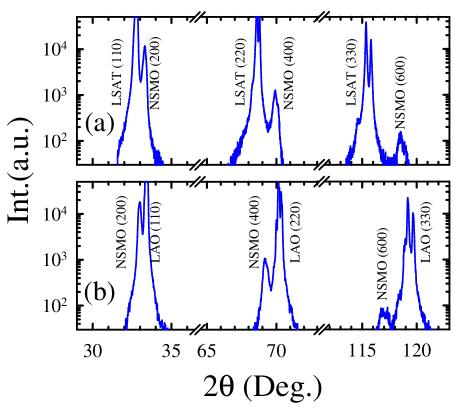
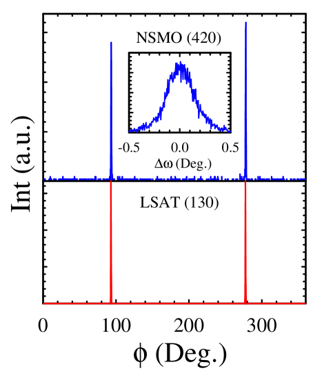
All of the films are orthorhombic with their longer axes in the film plane. Taking the axis in the growth direction, the (100) orientation of the films is indicated in x-ray diffraction - scans, shown for 130 nm-thick films grown on LSAT (110) and LAO (110) in Fig. 1 (a) and (b), respectively, by the presence of only film reflections near the substrate reflections. Phi scans of asymmetric film and substrate reflections, shown in Fig. 2 for the 130-nm film grown on LSAT, confirm the cube-on-cube orientation with NSMO [010]LSAT [10] and NSMO [001]LSAT [001]; the same orientation relationship was found for films grown on LAO. X-ray results for the films on NGO indicate NSMO [010]NGO [010] and NSMO [001]NGO [001].
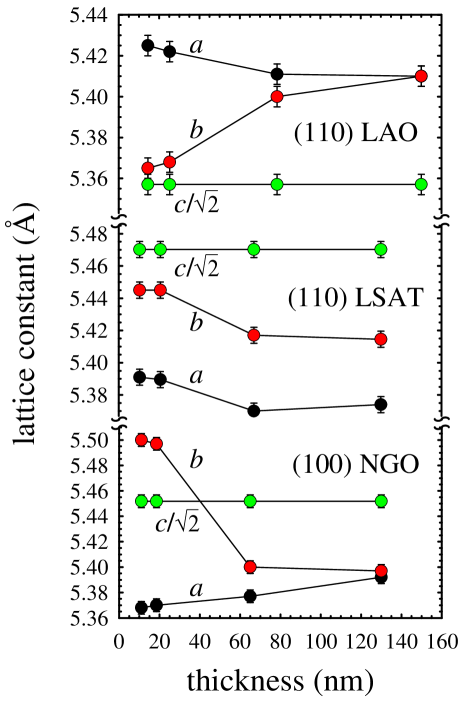
The lattice constants for all films were determined from reciprocal space maps in the vicinity of the the film (600), (440), (620), and (404) reflections, with nearby substrate reflections serving as internal references. The corresponding NGO reflections have the same indices as the films. For (110)-oriented LAO and LSAT the corresponding substrate reflections are (330), (400), (420), and (222), respectively. Figure 3 shows lattice constants as a function of film thickness for films on the three substrates. For all substrates and thicknesses, the film -axes are fully strained to those of the substrate. The and axis lengths are clearly relaxed in response to the compressive (LAO) and tensile (LSAT, NGO) in-plane strain along the film [010] directions, with the most substantial effect occurring for NGO.
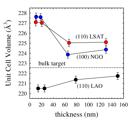
For LAO films the result is an expansion along [010] and contraction along the film normal ([100]), whereas for NGO films the -axes contract and the -axes expand. For both substrates the thickest film is tetragonal. The films on LSAT exhibit more modest contractions along both [010] and [100] with increasing thickness, maintaining tetragonality. In spite of these differences in behavior for the NGO and LSAT films under tensile strain, their unit cell volumes (Fig. 4) show very similar decreases with increasing thickness.
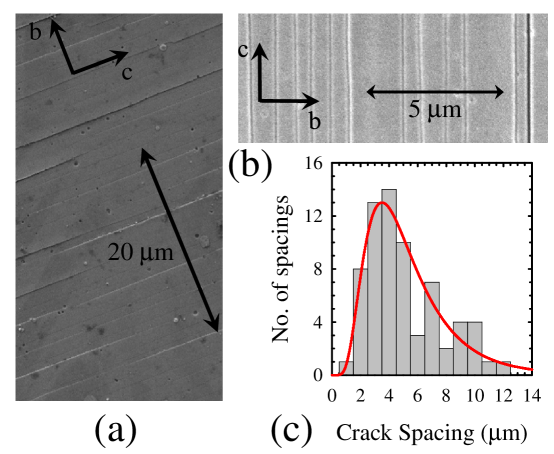
Scanning electron micrographs (Fig. 5) demonstrate that the relaxation of tensile strain along [010] for the films on NGO and LSAT is accommodated by the formation of unidirectional crack arrays running along the film [001] direction. The spacing of these cracks, determined from analyses of larger-area images from films on each of the substrates, approximately describes a log-normal distribution (shown in Fig. 5 (c)for the 65-nm NGO film), with median values of and for LSAT and NGO films, respectively. These distributions did not change appreciably with thickness for either substrate. The width of the cracks themselves varies within a given film (particularly evident in Fig. 5 (a) for the NGO film), and the mean crack width is greater in the thicker films. Though transverse-sectional microscopy was not pursued, as we discuss further below the transport data implies that the cracks do not penetrate through to the substrate.
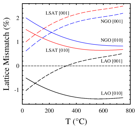
Similar crack arrays were observed previouslyOlsson for [110]-oriented YBa2Cu3O7-δ and PrBa2Cu3O7-δ films grown on [110] SrTiO3, where they were attributed to anisotropic thermal expansion mismatch between substrate and film upon cooling from the growth temperature. The same mechanism appears applicable to the present oxide film-substrate systems since, as noted above, NSMO has thermal expansion coefficients of opposite sign: positive along [010] and negative along [001]. The lattice mismatch, ( and are the substrate and bulk target lattice constants, respectively) is shown as a function of temperature in Fig. 6 along the [010] and [001] film directions for each of the three substrates. These curves were computed using published thermal expansion data for the substrates.LAOLSATExp ; NGOExpan The target lattice constants were measured up to 200∘C and their temperature dependencies found to match well those of Tobe et al. (Ref. Tobe, ) measured over a broader temperature range for compounds with a slightly different stoichiometry; the target data were then extended to higher temperature using the suitably scaled expansion data.
At the growth temperature (750∘C) the tensile mismatch for LSAT and NGO is greatest along the film [001] direction. Upon cooling, the mismatch along [001] decreases since the c-axis expands, while that along [010] increases. For the films on NGO the [010] mismatch approaches 2% at room temperature, the same amount by which the -axis lattice parameter decreases abruptly with increasing thickness. Although the calculated compressive mismatch along [010] for films on LAO is only 0.5% at room temperature, the compressed lattice is only stable at low thicknesses. Evidently there is a comparable critical thickness for NSMO above which both compressed and expanded lattices are relaxed.
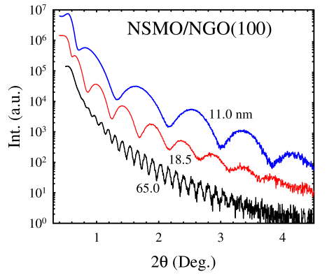
In spite of the linear crack arrays that develop in the thicker films under tensile strain, all of the films remain smooth as indicated by well-defined Kiessig oscillations seen in x-ray reflectivity measurements over an extended angular range (Fig. 7). Reflectivity simulationsSpirkle imply a film surface roughness with variance nm for the thinnest films, comparable to the perovskite unit cell dimension, with a modest increase for thicker films.
III.2 Transport Properties
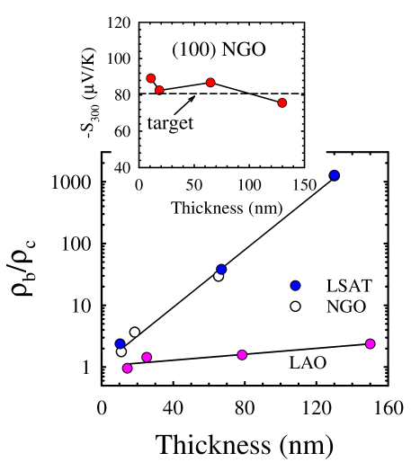
The dc electrical resistivity was measured for each film along the [010] and [001] directions as a function of temperature for K. Film resistances exceeding 1 G prevented measurements below K. The room-temperature resistivity anisotropy, , is found to increase approximately exponentially with increasing film thickness for the LSAT and NGO films (Fig. 8), reflecting principally an increase along [010] due to cracking. For the thickest films . The corresponding ratio for the LAO films also increases with thickness, reaching for the 150-nm film. As this thickest film is tetragonal with unit cell volume and closest to the bulk target (Fig. 3), we take the latter value to be representative of the intrinsic anisotropy of the NSMO compound.
To investigate the possibility that variations in oxygen content with thickness might contribute to the changes in resistivity, the room-temperature thermopower (TEP) was measured for all films. The TEP is a sensitive measure of Mn valence that is largely independent of cation in this region of the manganite phase diagramRaveau ; CohnCLMO . The value measured for the target was . The thermopowers for the films did not vary by more than for all thicknesses, typically falling in the range , as shown for the NGO films in the inset of Fig. 8. Thus significant and systematic variations in the oxygen content of the films with thickness are ruled out.
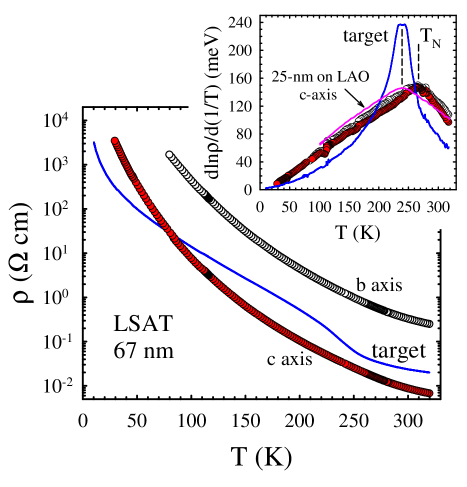
Fig. 9 shows the dependence of the in-plane resistivities for the 67-nm film grown on (110) LSAT along with that of the target. Interestingly, in spite of the substantial resistive anisotropy ( for this film), the dependencies are essentially identical along the [010] and [001] directions (inset, Fig. 9). This implies that the cracks do not penetrate into the substrate, since a stronger temperature dependence would be expected associated with thermally activated tunnel conduction as observed in other cracked manganite films.Fisher
The antiferromagnetic transition temperatures, , determined from maxima in vs. (inset, Fig. 9), are K for LSAT and NGO films, and K, the same as the bulk target, for films grown on LAO. In G-type AF’s like Ca1-ySryMnO3, expansion of the lattice due to Sr substitutionChmaissem enhances AF superexchange interactions (and ) due to an increase in the Mn-O-Mn bond angle. Stability of the C-type AF ordered state is increased by structural modifications tending to isolate the FM one-dimensional chains.CAFStability In the present films it seems likely that the significant enhancement of for films with expanded unit cells is principally due to the expansion along [001]. Though enhanced superexchange, e.g. due to an increase in the Mn-O-Mn bond angles along [100] and [010] is possible, the observation that for these films is independent of thickness, in spite of the very different -axis lengths due to cracking in the thicker films, argues against its prominent role in determining the increase in . More likely is that the expansion along [001] actually enhances the double-exchange coupling along [001] in this compound, thereby increasing the stability of the orbital and C-type Néel ordering.CAFStability We note that the -axis length in the bulk target is % smaller than that of a compoundKajimoto with K. Thus the observed increase in for the films under tension is consistent with existing data on the structure and phase behavior in this regime of composition, where is plausibly controlled principally by the -axis length.
IV CONCLUSION
Epitaxial -axis-oriented films of Nd0.2Sr0.8MnO3 have been grown under both compressive and tensile strain. The intrinsic resistivity anisotropy of the material, inferred from transport measurements on a 150-nm thick, compressively strained film, is . Uniaxial crack arrays oriented along the film [001] direction develop in films under tensile strain with thickness due to anisotropic thermal expansion mismatch upon cooling from the growth temperature. Typical crack spacings are a few . The resistivity anisotropy measured for the cracked films exceeds . Identical temperature dependencies of the resistivity along and transverse to the cracks implies that not all penetrate through to the substrate, and thus the large anisotropy is attributed to a thin and meandering conduction path for transport along [010]. The increased Néel temperature for films under tensile strain, from 240 K for the bulk target to 265 K independent of thickness, suggests that enhanced FM exchange stabilizes the orbital and spin order of the C-type AF state, and that their stability in this region of the phase diagram is largely controlled by the -axis length.
ACKNOWLEDGMENTS
We thank Mr. Alsayegh Husain for technical assistance with SEM scanning. This material is based upon work supported by the National Science Foundation under grants DMR-0072276 (Univ. Miami) and DMR-0504769 (Montana State Univ.), the Research Corporation (Univ. Miami), and the U.S. DOE Office of Basic Energy Sciences (Montana State Univ., Grant No. DE-FG-06ER46269).
† present address: 201-1650 Pembina Hwy., Winnipeg, MB R3T2G3 CA
References
- (1) R. Kajimoto, H. Yoshizawa, H. Kawano, H. Kuwahara, Y. Tokura, K. Ohoyama and M. Ohashi, Phys. Rev. B 60, 9506 (1999).
- (2) K. Tobe, T. Kimura, and Y. Tokura, Phys. Rev. B 67, 140402(R) (2003); ibid. 69, 014407 (2004).
- (3) R. Kajimoto, H. Yoshizawa, R. Kawasaki, K. Noda, and H. Kuwahara, J. Phys. Soc. Jpn. 74, 502 (2004).
- (4) R. Maezono, S. Ishihara, and N. Nagaosa, Phys. Rev. B 57, R13993 (1998); ibid. 58, 11583 (1998).
- (5) J. vs den Brink and D. Khomskii, Phys. Rev. Lett. 82, 1016 (1999); I. V. Solovyev and K. Terakura, Phys. Rev. B 63, 174425 (2001).
- (6) J. L. Cohn, M. Peterca, and J. J. Neumeier, Phys.Rev. B 70, 214433 (2004).
- (7) H. Tarashita and J. J. Neumeier, Phys. Rev. B 71, 134420 (2005).
- (8) E. Olsson, A. Gupta, M. D. Thouless, A. Segmüller, and D. R. Clarke, Appl. Phys. Lett. 58, 1682 (1991); M.D. Thouless, E. Olsson,and A. Gupta, Acta Metall. Mater. 40, 1287 (1992).
- (9) R. T. Murray, C. J. Kielly, and M. Hopkinson ;semicond. Sci. Technol. 15, 325 (2000).
- (10) M. D. Thouless, J. Am. Ceram. Soc. 73, 2144(1990).
- (11) B. C. Chakoumakos, D. G. Schlom, M. Urbanik, and J. Luine, J. Appl. Phys. 83, 1979 (1998).
- (12) W. Marti, P. Fischer, F. Altorfer, H. J. Scheel, and M. Tadin, J. Phys. Condens. Matter 6, 127 (1994); A. Senyshyun, L. Vasylechko, M. Knapp, U. Bismayer, M. Berkowski, and A. Matkovskii, J. Alloys and Compounds 382, 84 (2004); O. Chaix-Pluchery, B. Chenevier, and J. J. Robles, Appl. Phys. Lett. 86, 251911 (2005).
- (13) W. Spirkle, J. Appl. Phys. 74, 1776 (1993).
- (14) J. Hejtmánek, Z. Jirák, M. Marys̆ko, C. Martin, A. Maignan, M. Hervieu, and B. Raveau, Phys. Rev. B 60, 14057 (1999).
- (15) J. L. Cohn, C. Chiorescu, and J. J. Neumeier, Phys. Rev. B 72, 024422 (2005).
- (16) K. M. Satyalakshmi, B. Fisher, L. Patlagan, and G. Koren, Appl. Phys. Lett. 73, 402 (1998).
- (17) O. Chmaissem, B. Dabrowski, S. Kolesnik, J. Mais, D. E. Brown, R. Kruk, P. Prior, B. Pyles, and J. D. Jorgensen, Phys. Rev. B 64, 134412 (2001).