Surface Plasmon Interference Fringes in Back-Reflection
Abstract
We report the experimental observation of surface plasmon polariton (SPP) interference fringes with near-unity visibility and half-wavelength periodicity obtained in back reflection on a Bragg mirror. The presented method based on leakage radiation microscopy (LRM) represents an alternative solution to optical near-field analysis and opens new ways for the quantitative analysis of SPP fringes. With LRM we investigate various SPP interference patterns and analyze the high reflectivity of Bragg mirror in comparison with theoretical models.
pacs:
78. 67.-nThe development of optics at the micron and sub-micron scales requires the control over coherence of wave propagation in a confined environment as well as the knowledge of the optical properties of the structures used for this purpose. In this context the recent progresses in surface plasmon polariton (SPPs) Raether optics allowed the realization of optical elements as Bragg mirrors and beam splitters. These elements have been combined in various 2D SPP devices like a Mach-Zehnder interferometer Harry , or an elliptical resonator Drezet . In order to achieve SPP mirrors with very high reflectivity one has to study quantitatively the interaction of SPP waves and Bragg reflectors. In this context the quantitative near-field measurement of the reflectivity of Bragg mirrors integrated into SPP waveguides Weeber1 ; Weeber2 was reported. Here we propose an alternative method of analysis based on far-field leakage radiation microscopy (LRM) that we developed recently into a systematic routine Andrey . For this purpose we consider the back-reflection of propagating SPP waves impinging normally onto a Bragg mirror. In order to show the accuracy of the method we report experimental evidence for interference between incident and back-reflected SPP wave with a periodicity of ( being the SPP wavelength) and with a quasi-unity fringe visibility . We show that the results are consistent with the theoretical expectations and with an ideal SPP reflectivity of 100%. This in turn proves that back-reflection can be a useful tool for the local tailoring of the SPP intensity pattern by interference of incident and reflected SPP beams.
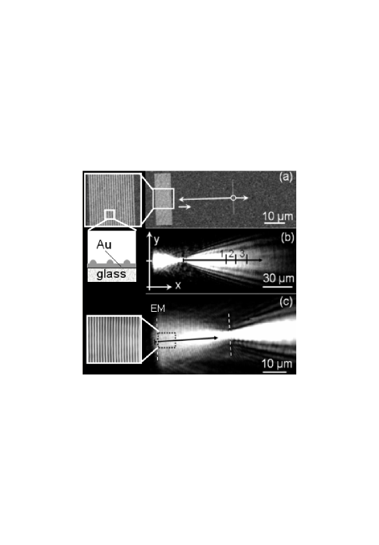
The Bragg mirror structures are constituted by a set of 20 parallel gold ridges (70 nm height, 150 nm width) fabricated by electron beam lithography (EBL) on glass subtrate Weeber1 . The distance between the ridges is nm (see Fig. 1a). At normal incidence this corresponds to Bragg reflectance maxima for a laser wavelength of 780 nm (Ti:sapphire). SPP waves are locally launched from an additional ridge (150 nm width) located in front of the Bragg reflector at a distance of m (see Fig. 1a). The laser beam is focused onto this ridge using a microscope objective (50, numerical aperture 0.7) and the laser spot diameter is around 2 m which corresponds to a full divergence angle of the SPP beam on the gold film of about . The SPP wave propagating to the left impinges normally on the Bragg mirror and is reflected back to the right giving rise to an interference pattern. Fig. 1b shows a LRM image Andrey ; Drezet of the SPP propagation obtained using an oil immersion objective (63 , numerical aperture=1.25). The absence of SPP transmittance behind the Bragg mirror leads to the conclusion that the incident SPP wave is mostly back-reflected.
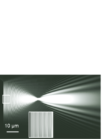
The diffraction behavior visible to the right of the launching ridge can be straightforwardly understood as a result of the interference between the SPP wave originating from the ridge and a virtual image-source located in the half-space to the left of the Bragg mirror. This is confirmed theoretically by simulating the SPP propagation with a simple scalar wave model Drezet (see Fig. 2) . The SPP field launched at the ridge is modelled by a continuous distribution of 2D dipoles whose orientation is in the sample plane and normal to the ridge direction. To simplify the calculation we considered a SPP mirror consisting of a single ridge located at the position of the Bragg reflector. The interaction of the incident SPP beam with this ideal mirror generates secondary SPP waves interfering with the incident beam to generate the observed lateral interference patterns to the right of the ridge. It is observed that despite the high value of the divergence angle the observed reflectivity is very high. This shows qualitatively that the reflectivity of this Bragg mirror is not very sensible to the incidence angle in a domain . This effect has already been observed in the near-field experiments mentioned Weeber1 and can be explained if we suppose that a periodical grating opens a gap in the angular dispersion curve of SPPs Barnes .
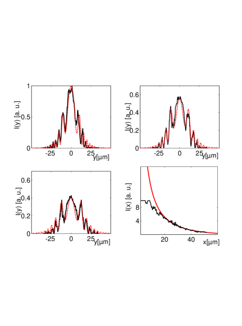
In order to analyze the SPP propagation we extracted different cross-cuts of the LRM images. The three transversal cross-cuts represented in Figs. 3a, b and c correspond to the directions and positions indicated in Fig. 1b. Fig. 3d shows a longitudinal cross-cut along the SPP propagation direction in Fig. 1b. Altogether these cross-cuts agree very well with the simulation if we adjust adequately the SPP propagation length and the effective mirror reflectivity which are the two free parameters of the model. Both transversal and longitudinal cross-cuts are necessary for fixing and . We find the best fit with a total reflectivity % and m which agrees with the value expected for a gold film Raether .
To understand the physical meaning of the value we now focus
our attention on the remarkable interference features present in
the region between the Bragg reflector and the launching ridge.
Indeed, in this region, as shown in the simulation (see inset on
Fig. 2), one expects theoretically interferences fringes with very
high contrast
close to one. We note that this effect is not visible in Fig. 1b,
since this figure is resolution limited due to the finite size of
the pixels on the charged-coupled-device camera used to acquire
the image. By increasing the magnification of the LRM note2
we however overcome this limit and we observe fringe interference
with a periodicity of 390 nm corresponding to
(see Fig. 1c). This observation can
seem rather surprising if we think of Rayleigh diffraction
limiting the spatial resolution to
with
, the oil immersion objective numerical aperture. One
should intuitively thus expect that the fringes will be blurred in
the image plane, as indeed incoherent optics predicts a reduced
visibility below % note . However, the SPP standing
wave pattern is a coherent phenomenon and it can be proven using
Fourier optics and Abbe’s theory Teich that the diffraction
limit does not affect the visibility Teich2 . In the
present case the immersion objective has a high numerical aperture
and we estimate that the unity fringe visibility existing in the
sample plane conserves its value in the image plane where we
expect thus
.
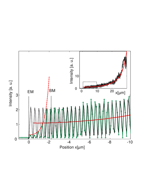
In order to analyze the fringes we plot a cross-cut in the
direction indicated by the black arrow in Fig. 1c. This cross cut
is depicted in the inset of Fig. 4. The red curve shows the
averaged intensity as simulated by the theoretical model which
reproduces the general trend of the intensity profile quite well.
The agreement is however not limited to the averaged intensity as
visible from the main curve of Fig. 4 which zooms a detail of the
inset close to the Bragg mirror. The oscillation fringes observed
experimentally coincide with the theoretical predictions and in
particular reproduce the very high contrast expected in this
region. A simple way to calculate the reflectivity is to
consider the ideal standing wave pattern obtained using two
counter propagative plane waves leading to the intensity
with
. Since this plane wave
hypothesis can be considered as valid in the vicinity of the Bragg
mirror boundary we deduce that should equal %. The
uncertainty is partly a result of the microscope diffraction limit
discussed before. It can be added that the consistency of the
argumentation is experimentally confirmed by the fact that an
incoherent illumination of the sample with an external light
source (not shown) does not allow us to resolve the separation
between the ridges constituting the Bragg mirror. Since the
periodicity of the fringes equals the one of the Bragg mirror it
indeed proves that an incoherent effect can not be invoked as a
justification for the quasi-unity fringes visibility observed with
SPPs. From these results and from the experimental fact that no
SPP is transmitted through the Bragg mirror (see Figs. 1 and 4)
one can thus conclude that 1) the transmission is below the
noise level, i. e., below 0.5% and 2) that a few percent of the
the incident SPP beam (i. e., S=5-10%) are scattered to light
into the glass substrate, this to accord to energy conservation.
It can be finally remarked that the mirror model used in this work
did not consider, to simplify the problem, the precise structure
of the Bragg mirror. This explains why in order to reproduce
accurately the experimental observation we must position precisely
the effective mirror (EM in Fig. 4) 2 m to the left of the
physical boundary corresponding to the first ridge of the Bragg
mirror (BM in Fig. 4). The experimentally observed effective
damping inside of Bragg’s mirror can be physically understood if
we consider that a SPP wave needs to propagate inside of the
periodical structure before being reflected back. This damping can
be well approximated by an exponential decay law whose propagation
length is around 500 nm.
In summary, we have presented an accurate method to measure reflectivity for SPP Bragg mirrors in normal incidence. The method based on LRM imaging allows the observation of standing wave fringes with a periodicity as small as and with a high contrast close to unity. The method due its sensibility constitutes a good complement to near-field measurements made on the same kind of structures Weeber2 . In all cases the observations are in good quantitative agreement with the theoretical expectations and show that the essential behaviors are well understood.
For financial support the European Union, under projects FP6 NMP4-CT-2003-505699 and the Lisa Meitner programm of the Austrian Science Foundation (M868-N08) are acknowledged.
References
- (1) H. Raether, Surface Plasmons(Springer, Berlin, 1988).
- (2) H. Ditlbacher, J. R. Krenn, G. Schider, A. Leitner, and F. R. Aussenegg, Appl. Phys. Lett. 81, 1762 (2002).
- (3) A. Drezet, A. L. Stepanov, H. Ditlbacher, A. Hohenau, B. Steinberger, F. R. Aussenegg, A. Leitner, and J. R. Krenn, Appl. Phys. Lett. 86, 074104 (2005).
- (4) J.-C. Weeber, M. U. González, A.-L. Baudrion, and A. Dereux, Appl. Phys. Lett. 87, Appl. Phys. Lett. 87, 1 (2005).
- (5) J.-C. Weeber, Y. Lacroute, A. Dereux, E. Devaux,T. Ebbesen, C. Girard, M. U. González, and A.-L. Baudrion, Phys. Rev. B 70, 235406 (2004).
- (6) A. Stepanov, J. R. Krenn, H. Ditlbacher, A. Hohenau, A. Drezet, B. Steinberger, A. Leitner, and F. Aussenegg, Opt. Lett. 30,1524 (2005).
- (7) W. L. Barnes, S. C. Kitson, T. W. Presit, and J. Sambles, J. Opt. Soc. Am. A 14, 1654 (1997).
- (8) By increasing by a factor 5 the focal length of the imaging lens located in front of the CCD camera (see Andrey ) we multiply the microscope magnification by the same factor.
- (9) From incoherent optics the original intensity pattern (where is the 2D position vector) is convoluted with the impulse response function of the objective . For the intensity pattern in the image plane one has with the absolute value of the transverse microscope magnification. If one obtains with % (we used the numerical approximation ).
- (10) M. Born and E. Wolf, Principles of optics, seventh (expanded ) edition (Cambridge University Press, Cambridge, 1999).
- (11) For the electric field of a coherent SPP wave which in the object plane has the form ( is the Bragg mirror reflectivity) one obtains in the image plane , e. g. , the convolution of with the impulse response of the objective for the field (compare note ). Since one deduces . It implies with the same visibility than the SPP wave intensity .