Energy-sensitive imaging detector applied to the dissociative recombination of D2H+
Abstract
We report on an energy-sensitive imaging detector for studying the fragmentation of polyatomic molecules in the dissociative recombination of fast molecular ions with electrons. The system is based on a large area (1010 cm2) position-sensitive, double-sided Si-strip detector with 128 horizontal and 128 vertical strips, whose pulse height information is read out individually. The setup allows to uniquely identify fragment masses and is thus capable of measuring branching ratios between different fragmentation channels, kinetic energy releases, as well as breakup geometries, as a function of the relative ion-electron energy. The properties of the detection system, which has been installed at the TSR storage ring facility of the Max-Planck Institute for Nuclear Physics in Heidelberg, is illustrated by an investigation of the dissociative recombination of the deuterated triatomic hydrogen cation D2H+. A huge isotope effect is observed when comparing the relative branching ratio between the D2+H and the HD+D channel; the ratio 2(D2+H)/(HD+D), which is measured to be at relative electron-ion energies around 0 eV, is found to increase to at eV.
pacs:
34.80.Lx, 34.80.Ht, 34.80.GsI Introduction
Dissociative recombination (DR) with electrons is the most important loss channel for molecular ions in cold dilute plasmas and a source of energetic neutral atoms and excited molecules DR-book . Rate coefficients, branching ratios, and the energy sharing between internal and external degrees of freedom of the fragments are thus important ingredients in modeling these plasmas. Even though a good understanding of the DR process of diatomic molecular ions has been reached in recent years, theory is not yet capable of supplying most of the information needed for these studies. Experimental investigations of the DR process in particular of polyatomic systems are thus still indispensable to further constrain the parameters of these models and to provide basic theory with detailed and reliable results for crucial benchmark systems.
Considerable experimental progress in studying the DR process has been made since the advent of heavy-ion storage rings with merging electron beam facilities, which allow to control the inner excitation of the molecular ions and the relative ion-electron energy precisely enough to produce data in the parameter space of interest for, e.g., planetary atmospheres or interstellar chemistry. Results obtained so far were vital in helping to unravel the processes governing the DR and to clarify many important and pertinent issues. But despite these experimental advances for particular diatomic systems, detailed investigations of the DR of more complex ions, such as measurements of branching ratios at relative energies other than zero, of the inner excitation of the molecular fragments or of their dissociation kinematics, are still hampered due to the limitations of presently available detection techniques in identifying the DR reaction products.
We have therefore developed an Energy-sensitive MUlti-strip detector system (EMU) that is capable of recording multi-fragment events following the DR of polyatomic molecular ions and to identify the fragments by their masses. The system has been installed at the ion storage ring TSR of the Max-Planck Institute for Nuclear Physics, which can store molecular ions of MeV energies and is equipped with an electron cooler as well as an electron target employing a cryogenic photocathode, so that electron-ion collision energies can be freely set in the meV to eV range with unprecedented resolution electron-target-TSR . While the main aim of the setup is to provide a universal tool for measuring DR branching ratios of polyatomic molecular ions into the different final fragment channels, the position resolution is sufficient to allow also for 2D imaging of the breakup geometries. The new setup has thus several advantages as compared to previous approaches PhysRevA1995-Datz-H2D+ , where grids of different transmissions (yielding a set of linear combinations of the rates for individual fragment channels) were employed in order to determine the branching ratios, a technique which is usually only applied at zero relative electron-ion energies for background reasons and which does not support molecular imaging.
The present paper discusses the concept and realization of the EMU detection system and exemplifies its properties and possibilities by using the new setup to investigate the dissociative recombination of D2H+. The DR of D2H+ was studied before in several storage ring experiments, and rate coefficients PhysRevLett2003-Lammich-D2H+ ; PhysRevA2008-Zhaunerchyk-D2H+ , the fragmentation geometry of the three-body channel PhysRevA2004-Strasser-D2H+ , and branching ratios PhysRevA2008-Zhaunerchyk-D2H+ have been reprted. The kinetic energy released in the three fragmentation channels, for ions and fragments in their ground states and relative ion-electron energies eV, are
| (1) |
The branching ratios measured at eV were reported to be =76.5(2.2) %, =13.5(1.5) %, and =10.0(0.7) % PhysRevA2008-Zhaunerchyk-D2H+ .
II The detector concept
Since the beam energies of the molecular ions stored in the TSR are very large as compared to the release energies occurring in DR experiments, the fragments resulting from a DR event of a molecular ion of mass number are traveling within a narrow cone around the ion beam axis, and the kinetic energy of the fragment is to a very good approximation given by
| (2) |
and is thus a measure of the mass number of the fragment. By recording separately the energies of all DR fragments of an DR event with a large area multi-hit-capable detector the fragmentation channel can be uniquely identified.
In the present setup the energy-sensitive multi-hit detector is realized by a large area (1010 cm2) position-sensitive, double-sided Si-strip detector (see Fig. 1). The energy- and position-sensitivity to particles hitting the detector is achieved through 128 vertical (x-) and 128 horizontal (y-) strips on the front and back side of the detector, respectively, which are read out individually by preserving the pulse height, i.e., the energy information. The readout system also ensures via the timing information that the detected particles belong to a single DR event. The detector is mounted about 10 m downstream of the electron target outside of the magnetic lattice of the TSR such that it can only be hit by neutral fragments.
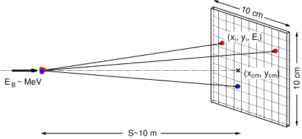
The impact of fragments from a single DR event on the detector leads to responding x-strips and responding y-strips with corresponding energies and , and the detection of all fragments can be easily verified by checking whether the two energy relations
| (3) |
are fulfilled. The measured fragment mass numbers and corresponding to the energies recorded on the individual strips are given by
| (4) |
In the following we will refer to the set of measured mass numbers , and the corresponding strip coordinates , as the ’hit pattern’ of the DR event.
The coordinates of the center-of-mass of the detected event in the detector plane are given by
| (5) |
and an estimate for the transversal kinetic energy release can be determined from the projected weighted distances defined by
| (6) |
using
| (7) |
where is the distance between the center of the electron target and the detector.
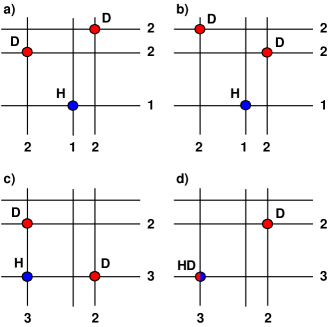
While Eqs. (3)-(7) are valid even in cases where more than one fragment hit the same strip, the strip-wise readout of only two coordinate planes together with the finite strip width leads to ambiguities in the determination of the breakup geometry from the hit pattern, which in some cases also affects the identification of the fragmentation channel. We shall first discuss these ambiguities for the specific case of the DR of D2H+, before we consider the more general case.
Figure 2 depicts the two most frequent of these ambiguities. The hit pattern shown in Fig. 2(a) is indistinguishable from the hit pattern shown in Fig. 2(b); this pattern thus results in two solutions concerning the fragmentation geometry. However, the identification of the fragmentation channel is still unique. This is no longer the case for the hit pattern shown in Fig. 2(c), where the H and the two Ds from the 3-body fragmentation channel are forming an L-shaped pattern with the H in the corner such that only two horizontal and two vertical strips are responding. This pattern cannot be distinguished from that shown in Fig. 2(d), which results from the detection of a molecular HD- and an atomic D-fragment from the 2-body channel (). Besides the even less likely occurrence of two or more fragments hitting the same x- and y-strip, i.e., the same ()-pixel, these L-shaped patterns are the only patterns in the DR of D2H+, which cannot be attributed uniquely to a fragmentation channel. Since the probability for the occurrence of this pattern is small due to the narrow strip width of m realized in the present setup, we attribute these patterns to the channel with the smaller number of fragments, that is for the case discussed in Figs. 2(c,d) to the HD+D channel. The influence of these miss-assignments on the accuracy of the branching ratios is small and can moreover be corrected for with the help of Monte Carlo simulations (see also Sec. V.1).
While the ambiguities caused by fragments hitting the same () pixel discussed above are present in case of all molecules, the other ambiguities depend on the multiplicity of identical fragment masses in the open fragmentation channels. In the DR of polyatomic molecules consisting of atoms of different masses such as HCO+, the identification of the fragmentation channel and of the fragmentation geometry is not subject to any other ambiguities. In the DR of polyatomic molecules, which contain several atoms of the same mass and fragment into channels containing two or more identical fragments, the main ambiguities hampering the identification of the fragmentation channels are again due to the L-shaped (sub-)pattern involving two identical fragments at the two ends of the L. The interpretation of hit patterns in terms of the fragmentation geometries is subject to similar ambiguities as discussed above, but the number of geometries leading to a specific pattern will strongly increase with the number of identical fragments. However, we again would like to point out that the center-of-mass determination by Eq. (5) and the transverse energy distribution defined by Eq. (7) are independent of these ambiguities.
III Experimental setup
III.1 The EMU detection system
The large area double-sided Si strip detector employed in the EMU detection system was built by the UK physics company Micron Semiconductor Limited micron . The detector has an active area of 97.3 mm 97.3 mm and an active depth of 300 m when biased by V (Fig. 3). Position sensitivity has been achieved by electronically subdividing the junction side into 128 vertical strips of 730 m width, which are separated by gaps of 30 m, and the ohmic side in 128 horizontal strips of 700 m width, which are separated by gaps of 60 m.
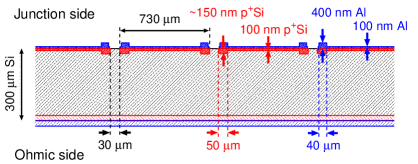
The thickness of the entrance (junction) window, which consists of a 100 nm-thick p+ doped Si layer covered with a 100 nm-thick aluminum coating, was minimized in order to keep the energy loss in the inert window material, and thus the cut-off energy for the detection of the heavy DR fragments, as small as possible. The increased thicknesses of the p+Si and the Al layer at the edges of the strips, which ensure a clean separation between the strips and a loss-free readout and which affect about 14 % of the active area of the detector, result in additional, slightly down-shifted peaks in the pulse height spectra; particles traversing this part of the entrance window suffer a larger energy loss which is specific for the fragment energy, mass, and its nuclear charge. This is discussed in more detail in Sec. IV in connection with the pulse height spectrum (Fig. 6) observed in the DR of D2H+. Since the penetration depth of the fragments in the detector material for energies available at the TSR is in most cases less than 10 m and the gap region close to the surface is almost field-free, fragments impinging in the gap region, covering about 4 % of the detector surface, will likely not be detected.
The detector is mounted in a dedicated chamber (Fig. 4) in the neutral fragment beamline BAMBI downstream of the electron target electron-target-TSR of the TSR. The distance from the center of the electron target to the front face of the detector is cm. At this distance the detector covers the full cone size for the DR fragments that is allowed by the beamtube (CF100). The maximum visible cone is in fact limited vertically by the height of the vacuum chamber in the TSR dipole magnet to about 8 cm diameter. A large bellow allows to retract the detector out of the beamline so that experiments with detectors further down the beamline are possible without breaking the vacuum. Moreover, the detector can be moved up and down in front of a retractable -source, which in turn can be moved horizontally using a translational stage, so that any part of the detector can be irradiated for testing and calibration purposes. The cryopump is vibrationally decoupled from the detector chamber to protect the wire bonds to the 256 strips of the detector from the mechanical noise of the pump. Under running conditions the vacuum in the detection chamber is about mbar. A mechanical shutter is furthermore installed in the pumping chamber to protect the detector during the injection phase of the ion beam into the storage ring.
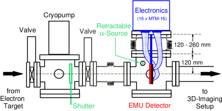

The 256 strips of the detector are read out by 16 highly integrated MTM-16 units developed by Mesytec mesytec , which are mounted directly on the upper lid of the detector chamber to minimize the length of the cables between detector and preamplifier. Each unit contains 16 channels consisting of a preamplifier, main amplifier, shaper and hold stage. Moreover, four input signals are added and compared to an adjustable discriminator level. The eight boards connected to the 128 x-strips and the eight boards serving the y-strips are daisy-chained to the two function blocks, respectively, of an MDI-2 unit developed by Mesytec as well. This one-slot VME unit allows one to do all the controlling, timing and read out of the 16 MTM-16 boards. A trigger signal is produced when one of the discriminators of the 16 MTM-16 units responded; it activates the hold stages of the MTM-16 units after 2 s, (i.e., only signals arriving within this time will be held) and starts the readout sequence. The individual pulse heights are digitized by a sliding scale ADC and - if above a programmable threshold - stored together with the strip number in a FIFO, which is read out via the VME interface. In the present configuration the readout speed is limited to about 2000 events per second. A schematic view of the electronic set up is shown in Fig. 5.
III.2 Specific settings for measuring the DR of D2H+
The first application of the EMU detection system was the investigation of the dissociative recombination of D2H+. D2H+ ions were produced in a Penning source, accelerated to MeV using an rf-quadrupole accelerator, and injected into the TSR; the stored ion current was up to about 4 A. After injection the ion beam was first phase-space cooled by the velocity-matched electron beam supplied by the electron target, which had a density of 9106 cm-3 and a transversal temperature of approximately 1.5 meV (expansion factor 20). At these conditions the effective length of the electron target is 115 cm, with an additional 20 cm on either end where the electron beam is merged with and demerged from the ion beam. After a few seconds the ion beam was phase-space cooled to a beam diameter below 1.0 mm.
The electron beam was then used as a target, either at matched or detuned electron velocities. The detuning energy , which measures the average electron-ion collision energy in the center-of-mass system, was adjusted to values between 0 and 20 eV by changing the acceleration voltage of the electron beam. At detuning energies the electron beam velocity was switched at a rate of 10 - 100 Hz between = 0 and the required energy in order to keep the ion beam phase-spaced cooled. Data was recorded between a few seconds and up to 30 s after injection, and count rates were limited to kHz.
IV Data analysis
The first analysis step consists of shifting the pulse height spectra of the individual strips to a common scale in order to compensate for the slightly different amplifications and offsets of the individual electronic channels using the D2H+ data.
The sums of all 128 x- and of all 128 y-strip spectra performed after this calibration step, are displayed in Fig. 6. While the overall energy resolution reached with the y-strips on the back side of the detector (e.g., (FWHM) keV for Ds of 0.96 MeV) is already very satisfactory, the resolution of the front side strips is worse by almost a factor of two. This is mainly due to the excess noise observed on the front side strips; while the back side of the detector is electronically well-shielded by a metal plate mounted directly behind the detector, the front side is unshielded in the direction of the storage ring. But although the resolution of the x-strips is not yet perfect, the peaks corresponding to the detection of an H, D, HD (or H+D), and D2 (or D+D) can be clearly identified. Even the small peak is visible that is caused by the detection of all fragments (D2H) on a single strip.

On the low-energy side of the peaks small satellite lines are visible. As already pointed out in Sec. III.1 these satellites are caused by particles passing through the slightly thicker parts of the entrance window. For light fragments as in the present case of the DR of D2H+ the resulting energy difference between the main and the satellite peak is small and thus does not hamper the mass assignment. For heavier fragments like carbon or oxygen, the energy difference will be larger and can correspond to one or more mass units. But even in these cases this will not lead to a misinterpretation of a DR event as the two energy sums [see Eq. (3)] will not be fulfilled. Disregarding these events, however, reduces the detection efficiency of the set-up and has to be taken into account by detailed simulations.
A more careful examination of Fig. 6(b) reveals a small number of counts between the peaks. These are mainly caused by events where the charges created by a fragment in the active volume of the detector are drifting to two adjacent y-strips such that the charge collected by each strip results in a reduced signal height. Such a pulse height splitting can be at least partly reconstructed by adding the signals of the two adjacent y-strips. A corresponding pulse height splitting on the front side of the detector is very unlikely to occur [see also Fig. 6(a)] as the range of the fragments in the detector material is so small that fragments hitting the gap between the x-strips are likely not be detected at all. As in the case discussed above, the influence of these effects on the detection efficiency is taken into account by simulations.
After the calibration procedure the pulse height of each of the 256 strips is compared to appropriately chosen windows around the mass peaks and, if it falls into one of these windows, the corresponding mass number is assigned to the strip. If the pulse height is above the lower threshold but does not fall into one of the mass windows, it is tested whether the sum with one of the neighboring strips fulfills this criterion. If yes, the corresponding mass is assigned to the strip with the larger signal while the other strip is ignored in the further analysis. We shall refer to this set of and and adjusted positions and , which are randomized across the width of the respective strip to avoid binning problems, as a hit pattern.
The next analysis step consists of checking whether the sums over all mass numbers and , respectively, observed in an event are equal to the mass number of the dissociating molecule, and whether the hit pattern corresponds to a possible DR fragmentation channel, i.e., whether there is any combination of the atomic constituents of the dissociating molecule that can explain the observed hit pattern. If yes, the event is marked as a DR event and the final fragment channel is assigned. Here, preference is given to the fragmentation channel with the smallest number of fragments. In the case of the DR of D2H+, for example, this means that the rather unlikely L-shaped hit pattern shown in Fig. 2(c), which results from the three-body breakup and cannot be distinguished from the hit pattern caused by the two-fragment channel HD+D as the comparison with Fig. 2(d) shows, is assigned to the HD+D channel.
An example for the extracted position distribution of fragments for a single fragment channel is given in Fig. 7, where the positions of the D2 (red) and the H (black) fragment of the D2+H channel following the DR of D2H+ at eV are shown in form of a scatter plot. One can clearly see the two circular shapes corresponding to the fragments with mass numbers 1 and 4, respectively.

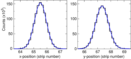
From the positions and and the mass numbers and the (transversal) center-of-mass position (, ) is calculated. The resulting x- and y-distributions of the center-of-mass position for events following the DR of D2H+ at = 0 eV are shown in Fig. 8. The data was taken 30 s after injection and continuous electron cooling, and exemplifies the good phase-space cooling that can be reached with the electron target of the TSR; taking the width of the strips into account the center-of-mass spread at the position of the detector is estimated to be mm (FWHM) in x- as well as in y-direction. In the further analysis of the data only events within a 2-ellipse around the centroid of the center-of-mass distribution are used to further suppress background events which might result from dissociative charge exchange reactions of the molecular ion with the residual gas of the TSR.
To investigate the influence of the detector properties and of the approximations and cuts used in the data analysis on the deduced results, and to allow for a detailed comparison with theoretical predictions for the DR process, a Monte Carlo simulation program has been developed. The simulation creates DR events at random position in the overlap region between the molecular ion beam and the electron beam and propagates them towards the detector. Subroutines are available to allow for an internal excitation of the ion and to incorporate different kinetic energy releases and angular distributions of the fragments with respect to the center-of-mass direction. At the detector, the impact position for each fragment is determined, which includes the decision as to which part of the entrance window was hit. The kinetic energy loss in the appropriate dead layer is subtracted for each fragment and a pulse proportional to the remaining kinetic energy is created on the strip being hit, broadening the pulse height by a Gaussian shaped resolution function. For fragments hitting the same strip the pulse heights are added. If the gap between two x-strips is hit, the fragment is assumed not to be detected. If the impact position happens to be in the gap between two y-strips of the back side, the signal is shared. The output of the program for a simulated event is a list of strip numbers and corresponding pulse heights. The simulated data are then treated with the same analysis tools as the measured data.
V Results for the DR of D2H+
V.1 Branching ratio at eV
The branching ratios for the three final fragment channels accessible in the DR of D2H+ at relative ion-electron energies of eV were determined by analyzing data taken after 30-50 s of electron cooling. Although the phase space cooling of the ion beam and the vibrational cooling of the ions is achieved already after s of electron cooling, the cooling was continued in order to lower the rotational temperature of the ions to values below the ambient room temperature of 300 K as shown in Ref. PhysRevLett2003-Lammich-D2H+ . The relative number of DR events leading to the three fragmentation channels (see Eq. (1)) are =76.69(4) %, =14.32(4) %, and =8.99(3) %, where the uncertainties given are of purely statistical origin. The Monte Carlo simulation was used to correct the measured numbers for the slightly different efficiencies for detecting and identifying the fragment channels. In this simulation the angular distributions of the fragments were assumed to be isotropic, but the population of the different vibrational states of the HD and D2 fragments as determined in Sec. V.3 was explicitly taken into account. The resulting corrections which had to be applied to the measured relative numbers given above amount to less than two percentage points.
The deduced branching ratios are compiled in Table 1. The uncertainties given are dominated by systematic errors caused mainly by the not yet fully understood detection efficiency for fragments hitting the gap regions. The ratios are compared to the result of a recent measurement performed at CRYRING PhysRevA2008-Zhaunerchyk-D2H+ using the grid method. Within the error bars the two measurements agree well despite the presumably different initial rotational temperatures of the D2H+ ions (see also the following section). As discussed already in Ref. PhysRevA2008-Zhaunerchyk-D2H+ the branching ratios display a clear isotope effect: On a purely statistical ground the HD+D channel should be twice as strong as the D2+H channel, i.e., in the absence of an isotope effect one would expect 2(D2+H)/(HD+D). However, the measured values result in a deuteration enhancement of 2(D2+H)/(HD+D), slightly smaller than deduced in Ref. PhysRevA2008-Zhaunerchyk-D2H+ but very similar to the ratio observed in the DR of H2D+ PhysRevA1995-Datz-H2D+ . These results clearly show that in the DR of deuterated H the formation of the two-body fragment channels containing the most deuterons is enhanced.
| Channel | This work | CRYRINGPhysRevA2008-Zhaunerchyk-D2H+ |
|---|---|---|
| () H+D+D | 78.0(0.4) | 76.5(2.2) |
| () HD+D | 13.5(0.3) | 13.5(1.5) |
| () D2+H | 8.6(0.2) | 10.0(0.7) |
V.2 Branching ratios at eV
To determine the branching ratios into the three fragment channels at relative ion-electron energies eV, data collection was started after 3 seconds of electron cooling when the ion beam was already fully phase space cooled. Moreover, at this time all ions are vibrationally relaxed while the rotational temperature is expected to be around 300 K or even slightly higher PhysRevLett2003-Lammich-D2H+ . Comparing the branching ratios at eV obtained after the shorter phase space cooling with those discussed in Sec. V.1, no difference was noticable within the limits of precision. After electron cooling, the energy of the electron beam was frequently switched between the cooling energy and the desired detuning energy eV, changing the latter from injection to injection to span the range between 0 up to 20 eV. The detuning-energy cycle was repeated several times to collect statistically reliable data. The branching ratio at each detuning energy was then obtained as described in Sec. V.1, including the corrections due to the slightly different detection efficiencies for the three fragment channels. Efficiency losses that could occur at high detuning energies due to the finite size of the detector were shown to be insignificant by investigating the distribution of impact positions of the fragments on the detector; at high detuning energies a considerable part of the maximal available release energy is not converted into kinetic energy of the fragments, but into internal excitation energy of the fragments. Moreover, background events from dissociative charge exchange collisions with the residual gas were found to be negligible at all measured ion-electron energies.
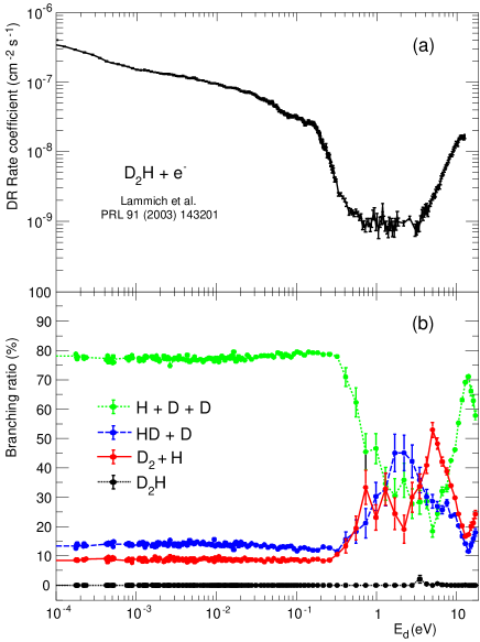
Figure 9 shows the extracted fragment channel branching ratios in the range of = 0.2 meV to 20 eV together with the DR rate coefficient measured in a previous experiment at the TSR under similar cooling conditions PhysRevLett2003-Lammich-D2H+ . As to be expected, the probability for the recombination channel D2H, which requires the emission of a stabilizing photon in times comparable to the dissociation times, is found to be consistent with zero to within better than 1%. The branching ratios into the fragmentation channels are observed to be more or less constant up to 300 meV at values close to those obtained at eV, even though the DR rate coefficient drops by two orders of magnitude. In particular, the isotope effect observed at eV persists over this energy range and is even increasing for energies meV. For higher energies the branching into the three-body channel is declining quickly and reaches a minimum level of about 20 % between 4 and 5 eV, while the relative intensities of the two-body channels are both rising. At =2 eV the HD+D channel is the dominant fragmentation channel ((HD+D)45 %), but at around 5 eV the D2+H channel is even reaching (D2+H) 55 %, exhibiting a huge isotope effect of 2(D2+H)/(HD+D). At energies above 10 eV the three-body channel regains its role as the dominant fragment channel with a branching ratio above 60 %.
We are not aware of earlier measurements of the fragment branching ratios following the DR of D2H+ at detuning energies eV. However, Datz et al. PhysRevLett1995-Datz-H3+ ; PhysRevA1995-Datz-H2D+ have measured these ratios in the energy range between 1 meV and 20 eV for the DR of H and its isotopomer H2D+. The overall behavior of the relative branching ratio between the combined two-body channel and the three-body channel is rather similar for all three systems investigated, and the gross structure of this ratio has been successfully attributed to the successive opening of the electronically excited two-body fragment channel H()+H, H()+H and of the three-body channel H()+H()+H() within a statistical approach PhysRevA2001-Strasser-H3+vib . However, while in the DR of H2D+ the relative fractions of the two two-body channels seem to stay constant over the measured range of energies, we find that this fraction strongly changes in the DR of D2H+ at energies between eV, leading to a drastic isotope effect around eV that is yet to be explained.
V.3 Vibrational excitation of fragment molecules
Standard imaging techniques without mass identification have difficulties identifying and separating two-body fragmentation channels in DR experiments involving polyatomic molecular ions. The event-by-event mass identification of all fragments provided by the EMU system allows for a straight-forward analysis of these channels.

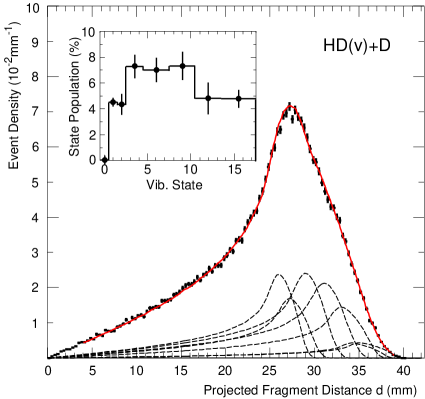
The normalized projected distance distributions for the two two-body fragment channels D2+H and HD+D observed in the DR of D2H+ at eV are displayed in Fig. 10 using data collected after 30 s of electron cooling. Following common practice (see e.g., Ref. PhysRevA2002-Strasser-H3+D3+ ), the distance between the two fragments in the detector plane is plotted rather than the weighted projected distance defined by Eq. (6). The projected distance distributions carry information about the kinetic energy release as well as about the angular distribution of the fragments with respect to the ion (electron) beam direction novotny . Since at eV the angular correlations are expected to be isotropic for symmetry reasons, can be readily analyzed to yield the kinetic energy release distribution.
In both channels only the vibrational states built on the electronic ground state of the fragments are energetically accessible, i.e., the available final states are D+H1s with = 0 to 20 and HD+D() with = 0 to 17, respectively. The relative populations of these states, which are derived from a fit of the projected distance distributions using simulated distributions for individual vibrational states, are shown in the inserts. In the simulation we assume the rotational temperature of the parent ion to be 100 K (see also further below) and the DR rate coefficients to be constant for all rotational angular momenta. For these fits some vibrational levels were grouped together and an equal population was assumed within each group to reduce the uncertainties caused by the anticorrelation of contributions between energetically close levels; they are nevertheless still dominating the accuracy of the deduced populations.
The derived population distributions of the vibrational levels for the molecular fragment are similar for both channels and similar to the distributions measured by Strasser et al. PhysRevA2002-Strasser-H3+D3+ in the DR of H and D. They all show a bell shape-like behavior, close to what is expected from a simple phase space argument PhysRevA2001-Strasser-H3+vib .
V.4 The three-body channel H+D+D
Also in studies of DR fragmentation channels which result in a total breakup of the molecule into its atomic constituents, the EMU system has some advantages as compared to standard imaging techniques based on micro-channel plates and an optical readout, even though the latter usually exhibits a considerably better position resolution (e.g., m novotny as compared to 750 m of the EMU detector). Besides the unambiguous fragment identification, the advantage is in particular the high data rate of up to 2000 Hz that can be handled by the EMU system (to be compared to, e.g., Hz of the TSR optical imaging setup novotny ).
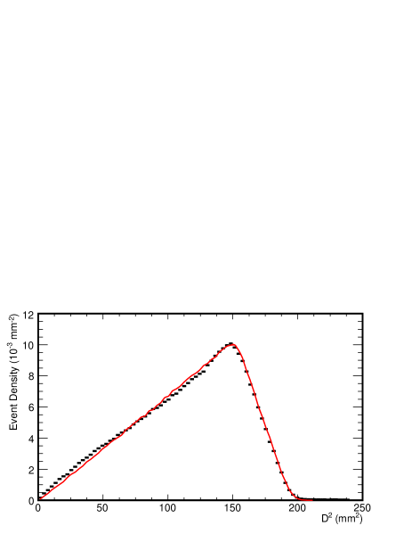
In the DR of D2H+ at eV the three atomic products can only be formed in their electronic ground states. The total kinetic energy release in the D+D+H channel is thus uniquely determined by the ground state energy release of D2H+ with respect to the asymptotic free neutral atomic products plus the remaining excitation energy of the D2H+ molecule, which we describe by a (rotational) temperature. As discussed in Sec. II, the weighted projected distance , which is not affected by any of the ambiguities in the fragmentation geometry determination, is proportional to the transverse energy release. The distribution of the weighted projected distances thus provides information on the total kinetic energy release.
The measured distribution, derived from data collected after 30 s of electron cooling, is plotted in Fig. 11 together with the simulated distribution, which was calculated assuming that the three fragments are isotropically distributed in the available phase space and also assuming eV and a rotational temperature of 100 K. While the edge of the distribution at large , which is most sensitive to the total kinetic energy release, is very well described by the simulation assuming a subthermal rotational temperature of 100 K (see also Ref. PhysRevLett2003-Lammich-D2H+ ), there are small but statistically relevant deviations on the left shoulder of the distribution, which are likely caused by anisotropies in the momentum distribution between the three fragments.
Although we only have access to the transverse kinetic energies of the fragments, it has been shown before PhysRevA2002-Strasser-H3+D3+ ; PhysRevA2004-Strasser-D2H+ that information about the momentum distribution between the three fragments can be gained employing a slightly modified concept of Dalitz coordinates and Dalitz plots. The coordinates and originally introduced by Dalitz PhilosMag1953-Dalitz-Dalitzplots are linear combinations of the kinetic energies of the three fragments in the center-of-mass frame, taking into account energy and momentum conservation. By plotting the number of events as a function of and , the momentum correlations between the fragments can be visualized. In particular, for a purely statistical, phase-space dominated breakup the Dalitz plot is evenly populated. The modified concept PhysRevA2002-Strasser-H3+D3+ ; PhysRevA2004-Strasser-D2H+ ; lammich ; PhysRevA2007-Nevo-CH2+ consists in defining projected Dalitz coordinates and by replacing by the corresponding transverse energy and by plotting the number of events as a function of and instead of and . The measured distribution is then divided by a simulated distribution assuming a phase-space dominated breakup in order to account for possible detection efficiency variations and to regain a uniformly populated Dalitz plot in case no momentum correlations between the fragments exist. We will refer to these plots as Dalitz ratio plots.
In the case of the DR of D2H+ where two of the three fragments are identical, the projected Dalitz coordinates and are conveniently defined as lammich
| (8) | |||||
| (9) |
with
| (10) |
and . The allowed values of and are confined by 1/9.
In filling the Dalitz ratio plot two ambiguities have to be considered. The first is connected with the indistinguishability of the two Ds, which leads to two entries: at and . The second one is specific to the EMU system and is caused by the ambiguity [see Figs. 2(a) and 2(b) and Eq. (10)] in deducing the breakup geometry from the hit pattern. This leads to two additional entries at and and to a smearing of structures along the coordinate. The resulting Dalitz ratio plot, divided by the distribution for an isotropic breakup of D2H+, is shown in Fig. 12. It is quite obvious that the momentum distribution is far from being isotropic and that linear decay geometries are enhanced by up to 40%, where one of the Ds and the H are emitted back-to-back with the second slow D remaining in the center.
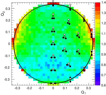
The present result agrees with the result obtained in Ref. PhysRevA2004-Strasser-D2H+ using standard 2D-imaging, but the almost two order of magnitude higher event rates that can be handled by the EMU system are resulting in improved statistics and thus in a considerably clearer picture. The statistics which can now be attained in these measurements should finally be sufficient to employ the Monte Carlo image restoration technique discussed in Ref. PhysRevA2004-Strasser-D2H+ with strongly reduced artificial noise patches. This will allow for a more quantitative analysis of the momentum distributions.
VI Summary
The potential of the EMU imaging system for studying the dissociative recombination of polyatomic molecular ions with electrons in merged beam experiments is clearly borne out by the results obtained for the DR of D2H+. The main advantage of the new set up, which is based on a large area, energy and position sensitive Si detector with multi-hit capabilities, is the possibility to determine the individual masses of the fragments on an event-by-event basis. This allows one to efficiently distinguish DR events leading to only neutral fragments from DR and background events involving charged fragments, to uniquely identify these fragmentation channels, and to determine their branching ratios as a function of the relative ion-electron energy. While the position resolution, which is limited by the width of the read-out strips to m, cannot compete with the resolution of m of optical imaging systems, it is nevertheless sufficient to allow for detailed studies of total kinetic energy releases and transverse breakup geometries of the different fragmentation channels by 2D imaging; the lack of position resolution is at least partly compensated by the times higher event rate that can be handled by the EMU system, resulting in data of high statistical quality. Moreover, in DR studies of polyatomic molecular ions involving heavier fragments, also the smaller minimum distance between two fragments that can be resolved by the EMU detector as compared to MCP/CCD-based 2D-imaging systems can be an additional advantage.
Comparing the results obtained in the present investigation of the DR of D2H+ with results of earlier measurements, where available, generally good agreement is observed. In particular, the branching ratios of 78.0(0.4) %, 13.5(0.3) % and 8.6(0.2) % measured at eV for the D+D+H, HD+D, and D2+H channels, respectively, confirm the results recently obtained at CRYRING PhysRevA2008-Zhaunerchyk-D2H+ using the transmission-grid method. The branching ratios as a function of collision energy were measured for the first time. While the general trend of the ratio of the combined two-body to the three-body fragmentation channel looks rather similar to what has been observed before for H PhysRevLett1995-Datz-H3+ and H2D+ PhysRevA1995-Datz-H2D+ , the relative branching ratios between the D2+H and HD+D channels display an unexpectedly large isotope effect. Whereas the ratio 2(D2+H)/(HD+D) is expected to be 1 in the absence of any isotope effect, this ratio is found to be enhanced by about 25% at most energies investigated, and moreover reaches a so far unexplained large value of 3.7(0.5) at eV.
Acknowledgements.
HB acknowledges partial support from the German-Israeli Foundation for Scientific Research and Development (G.I.F.) under Grant I-900-231.7/2005 and by the European Project ITS LEIF (HRPI-CT-2005-026015). DS acknowledges support by the Weizmann Institute of Science through the Joseph Meyerhoff program. Support by the Max-Planck Society is acknowledged.References
- (1) M. Larsson and A. E. Orel, Dissociative Recombination of Molecular Ions (Cambridge University Press, Cambridge, 2008).
- (2) F. Sprenger, M. Lestinsky, D. A. Orlov, D. Schwalm, and A. Wolf, Nucl. Instrum. Methods A 532 298 (2004); D. A. Orlov, U. Weigel, D. Schwalm, A. S. Terekhov, and A. Wolf, ibid. 532 418 (2004); M. Lestinsky et al., Phys. Rev. Lett. 100 033001 (2008).
- (3) S. Datz, M. Larsson, C. Stromholm, G. Sundström, V. Zengin, H. Danared, A. Källberg, and M. af Ugglas, Phys. Rev. A 52 2901 (1995).
- (4) L. Lammich et al., Phys. Rev. Lett. 91 143201 (2003).
- (5) V. Zhaunerchyk, R. D. Thomas, W. D. Geppert, M. Hamberg, M. Kaminska, E. Vigren, and M. Larsson, Phys. Rev. A 77 034701 (2008).
- (6) D. Strasser, L. Lammich, H. Kreckel, M. Lange, S. Krohn, D. Schwalm, A. Wolf, and D. Zajfman, Phys. Rev. A 69 064702 (2004).
- (7) www.micronsemiconductor.co.uk
- (8) www.mesytec.de
- (9) S. Datz, G. Sundström, Ch. Biedermann, L. Broström, H. Danared, S. Mannervik, J. R. Mowat, and M. Larsson, Phys. Rev. Lett. 74 896 (1995).
- (10) D. Strasser, J. Levin, H. B. Pedersen, O. Heber, A. Wolf, D. Schwalm, and D. Zajfman, Phys. Rev. A 65 010702(R) (2001).
- (11) D. Strasser, L. Lammich, H. Kreckel, S. Krohn, M. Lange, A. Naaman, D. Schwalm, A. Wolf, and D. Zajfman, Phys. Rev. A 66 032719 (2002).
- (12) S. Novotny et al. Phys. Rev. Lett. 100 193201 (2008).
- (13) R. H. Dalitz, Philos. Mag. 44 1068 (1953)
- (14) L. Lammich, PhD-thesis (Univ. Heidelberg, 2004), www.ub.uni-heidelberg.de/archiv/4833
- (15) I. Nevo et al., Phys. Rev. A 76 022713 (2007).