Synthesis of Reversible Functions
Beyond Gate Count and Quantum Cost
Abstract
Many synthesis approaches for reversible and quantum logic have been proposed so far. However, most of them generate circuits with respect to simple metrics, i.e. gate count or quantum cost. On the other hand, to physically realize reversible and quantum hardware, additional constraints exist. In this paper, we describe cost metrics beyond gate count and quantum cost that should be considered while synthesizing reversible and quantum logic for the respective target technologies. We show that the evaluation of a synthesis approach may differ if additional costs are applied. In addition, a new cost metric, namely Nearest Neighbor Cost (NNC) which is imposed by realistic physical quantum architectures, is considered in detail. We discuss how existing synthesis flows can be extended to generate optimal circuits with respect to NNC while still keeping the quantum cost small.
1 Introduction
Power dissipation becomes an important issue for designing high performance digital circuits. While a significant part of energy dissipation is due to the non-ideal behavior of transistors and materials, the other part is caused by the fundamental Landauer principle introduced in 1961 [1]. Landauer proved that using conventional (irreversible) logic gates leads to a certain energy dissipation regardless of the underlying technology. More precisely, energy is dissipated each time a bit is lost during the computation. In 1973, Bennett showed that to avoid power dissipation in a circuit, it must be built from reversible gates [2]. Currently, the field of reversible computing has received considerable attention in particular in low-power CMOS design [3, 4].
Furthermore, quantum gates are inherently reversible so that reversible logic builds the basis in the domain of quantum computation. It has been shown that quantum computing significantly improves the rate of advance in processing power for dedicated applications [5]. For example the factorization problem cannot be executed on a classical Turing machine as efficiently as on a quantum computer. Since conventional CMOS technology suffers from the miniaturization and the exponential growth of the number of transistors, quantum computing received significant attention as a promising alternative in the last years.
However, quantum algorithms and reversible logic will finally need hardware for the implementation. So far, several technologies have been developed where each one has its own strengths and drawbacks (see e.g. [4, 6, 7]). In particular, current quantum technologies lead to completely new challenges for the researchers which need to be resolved for having a practical device. Thus, to reach a realizable hardware, synthesis approaches have to consider the physical limitations as well. Nevertheless, most of the currently available synthesis algorithms often only consider gate count and quantum cost (see e.g. [8, 9, 10, 11, 12, 13, 14]). But depending on the application, the addressed technology, or the final quantum architecture other cost metrics beyond quantum cost and gate count have to be addressed as well.
In this paper, we first give an overview of technology-related metrics that should additionally be considered while synthesizing quantum or reversible logic. Thereby, we focus on metrics which can be modelled in such a way that they are still applicable to existing synthesis approaches. In doing so, the applicability of the available synthesis methods is ensured while the results can be optimized with respect to constraints closer to the physical realization. Our analyses reveal that considering these metrics may lead to new conclusions about the performance of synthesis approaches in a respective domain.
Second, we demonstrate how existing synthesis flows can be extended to optimize the resulting circuits with respect to one of these new cost criteria. To this end, we propose methods to optimize the Nearest Neighbor Cost (NNC) for Linear Nearest Neighbor (LNN) architectures where only adjacent qubits may interact with each other. LNN architectures are often considered as an appropriate approximation of a scalable quantum architecture (see e.g. [15, 16, 6]). While NNC optimality can be achieved by applying additional SWAP gates, it increases the quantum cost by about one order of magnitude. Thus, we propose improvements that reduce the resulting quantum cost by more than 50% on average (83% in the best case). As a result, by considering a new technological constraint, a synthesis flow is suggested that goes beyond the previous synthesis paradigms.
The rest of this paper is organized as follows. In Section 2 basic concepts are introduced. In Section 3 a comprehensive overview of technology-related metrics for the synthesis stage is given and discussed. The NNC-optimal synthesis flow for quantum logic is proposed in Section 4 followed by the optimization methods presented in Section 5. Our experimental results are described in Section 6. Finally, we draw some conclusions and sketch future work in Section 7.
2 Background
2.1 Reversible Logic
A reversible function over variables maps each input assignment to a unique output assignment. Such function must have the same number of input and output variables. A circuit realizing a reversible function is a cascade of reversible gates. Common reversible gates include:
-
•
A multiple control Toffoli gate [17] has the form , where is the set of control lines and with is the target line. The value of the target line is inverted iff all control lines are assigned to 1. For =0 and =1, the gates are called NOT and CNOT, respectively. For =2, the gate is called C2NOT or Toffoli.
-
•
A multiple control Fredkin gate [18] has two target lines and control lines. The gate interchanges the values of the target lines iff the conjunction of all control lines evaluates to 1. For =0, the gate is called SWAP gate.
-
•
A Peres gate [19] has one control line and two target lines and , and is a and a in a cascade.
In this paper, is particularly used to denote the number of inputs and outputs. Outputs (inputs) that are not required in the function specification are considered as garbage (constant) lines. The notations and are used as the number of constant inputs and number of garbage outputs, respectively.
2.2 Decomposition to Quantum Logic
Quantum logic is inherently reversible [5] and manipulates qubits rather than pure logic values. A qubit is a two-level quantum system, described by a two-dimensional complex Hilbert space. The two orthogonal quantum states are used to represent the values 0 and 1. The state of a qubit for two pure logic states can be expressed as (called superposition), where and are complex numbers so that .
Each Toffoli, Fredkin, or Peres gate can be decomposed into a quantum circuit composed of a sequence of elementary quantum gates [5] defined as follows:
-
•
Inverter (NOT): A single qubit is inverted.
-
•
Controlled-NOT (CNOT): The target qubit is inverted if the control qubit is 1.
-
•
Controlled-V: Performs the V operation known as the square root of NOT, since two consecutive V operations are equivalent to an inversion.
-
•
Controlled-V+: Performs the inverse of V .
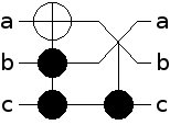
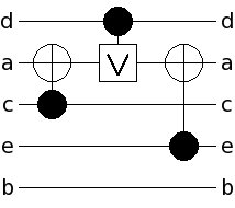
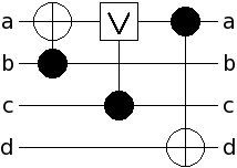
Fig. 1(a) shows a Toffoli and a Fredkin gate in a cascade. The resulting (decomposed) quantum circuit is depicted in Fig. 1(b).

3 Cost Metrics
In order to address various technical constraints in the synthesis stage, metrics have been proposed that are used to evaluate the respective results. Among them, gate count and quantum cost received most attractions and are widely applied (e.g. see [8, 9, 10, 11, 12, 13, 14]). However, other cost metrics imposed by target technologies exist and need to be considered.
The aim of this section is to introduce those metrics which can be used to guide a synthesis tool to construct realizable circuits. It is worth noting that there are other (physical) metrics like duration of pulse sequences and number of traps that their considerations need some interactions between various steps of the design cycle of quantum and reversible circuits. However, the focus of this paper is on those cost metrics that can be used in the synthesis step.
While the introduced metrics are related to the physical realizations of quantum and reversible logic more than the ones have been applied so far, they can be simply used by the available synthesis tools too. As the experimental results show such considerations can lead to a different (and more realistic) evaluation of synthesis approaches.
3.1 Number of Lines and Constant Inputs
Number of lines , constant inputs , and garbage outputs are common metrics to measure the quality of synthesized circuits. Even if these measures are negligible for reversible CMOS technologies (see e.g. [4]) they have high importance in quantum computation where each qubit must be represented by a physical entity that supports distinct and superposition states. Currently, such entities are not arbitrarily available in quantum technologies111Current systems contain e.g. 12 [20] or 28 qubits [21], respectively.. Besides that, initializing quantum registers cannot be simply done because of the exponential state-space of an -qubit register (see the method proposed in [22]). Thus, synthesis approaches should keep track of , , and if quantum circuits are particularly addressed.
3.2 Gate Count and Quantum Cost
Number of gates has been used to evaluate nearly all synthesis approaches so far. For an arbitrary circuit with gates , , , , the gate count metric is denoted as and defined as . Besides that, quantum cost are used to measure the implementation cost of quantum circuits. More precisely, quantum cost is defined as the number of elementary quantum operations needed to realize a gate (see Table 1). In addition, the quantum cost for a circuit is defined as . Obviously, quantum cost should be considered in particular if quantum circuits are addressed.
3.3 Transistor Cost
In order to realize Toffoli or Fredkin gates on reversible CMOS technologies (as done e.g. in [4]), a number of transistors is required where its complexity depends on the number of control lines of the respective gate. This metric is denoted as in the rest of the paper. It is defined by where is the number of control lines of a given gate [25]. The of a circuit is defined as the sum of the s of its gates.
3.4 Nearest Neighbor Cost (NNC)
Although most quantum algorithms presume that interaction between arbitrary qubits is possible with no extra cost, some restrictions exist in real quantum technologies. As an example, in a Linear Nearest Neighbor (LNN) architecture only adjacent qubits are allowed to interact222The LNN architecture is often considered as an appropriate approximation to a scalable quantum architecture. If one can show that a circuit can be efficiently reorganized to be executed in the LNN architecture, such a circuit could be run efficiently in many other architectures [15, 16, 6].. Hence, gates of the same type (e.g. all 3-bit Toffoli gates) do not necessarily have the same implementation cost. To measure this, a new cost metric denoted NNC is introduced:
Consider a 2-qubit quantum gate where its control and target are placed at the and line (), respectively. The NNC of is defined as , i.e. distance between control and target lines. The NNC of a circuit is defined as the sum of the NNCs of its gates. Optimal NNC for a circuit is 0 where all quantum gates are either 1-qubit or 2-qubit gates performed on adjacent qubits.
-
Benchmark NNC RMS BDD RMS BDD RMS BDD RMS BDD RMS BDD RMS BDD RMS BDD RMS BDD RMS BDD 4mod5_8 5 7 4 6 1 3 8 8 12 24 16 41 10 24 4,6 6,71 64 88 alu_9 5 7 4 6 0 2 13 9 45 29 39 45 42 28 18,2 8,14 152 104 decod24_10 4 6 0 2 2 4 18 11 86 27 88 33 82 26 35,8 8,5 240 96 hwb9_65 9 170 0 161 0 161 2223 699 23178 2275 43624 118639 18022 1997 4194,6 26,62 31136 8544
3.5 Circuit Depth
Consider two consecutive gates and with control sets and and with target sets and , respectively. These gates can concurrently be applied if and ( and may have some common elements). Suppose a quantum circuit with elementary gates. Assume that contains subcircuits with concurrent gates where the subcircuit contains concurrent elementary gates. The circuit depth is defined as the number of steps required to execute all available gates in a circuit, i.e. .
Since the time which a qubit can keep its quantum state (the coherence time) and the time needed to perform a gate (the gate operation time) may vary from one technology to another (for example see Table III of [26]), considering the circuit depth at the synthesis stage for quantum circuits is vital. Despite the fact that quantum algorithms already exploit algorithmic parallelism to increase the processing speed, synthesis algorithms should produce concurrent gates for efficient quantum circuit implementation.
3.6 Gate Distribution
As mentioned above, coherence time for qubits and operation time for gates are widely affected by technological parameters. It can be verified that the total operation time of gates applied to a qubit must be less than its qubit de-coherence time; otherwise the qubit value is lost before applying all gates. The number of elementary gates applied to the qubit of a quantum circuit is denoted as . Average, minimum, and maximum number of applied elementary gates are denoted as , , and , respectively. By considering and , designers may want to balance the distributions of all qubits for quantum circuits.
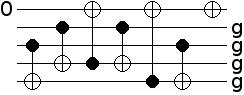
3.7 Discussion
As an example of the various cost metrics, Fig. 2 shows a circuit with , , , , , NNC = 9, , , , , and . Although, gate count () and quantum cost () have been extensively used for the evaluation of circuit quality so far, consideration of additional metrics as introduced above may lead to different judgements about the quality of a circuit. To illustrate this, Table 2 compares different costs of some benchmark circuits obtained from two different synthesis approaches, namely the Reed-Muller spectra approach [9] (denoted by RMS) and the BDD-based method [14] (denoted by BDD)333We like to thank the authors of both approaches for making us their tool available..
As shown in Table 2, if only gate count and quantum cost are used for the evaluation, one must conclude that the BDD-based approach leads to the best results. However, if further cost metrics are considered the results become very different. For example, the RMS approach leads to better realizations in terms of NNC and number of lines. That is, if quantum circuits should be built, the results obtained by this approach are better. In contrast, if reversible CMOS circuits are addressed, the number of lines are negligible and NNC can be ignored. Since additionally the transistor count is lower, the circuits obtained by the BDD-based method are the better choice for this domain.
Altogether, cost metrics beyond gate count and quantum cost should be used to control the synthesis so that circuits with special properties (e.g. few circuit lines, an NNC of 0, etc.) result. But the consideration of various constraints at a single step complicates the respective algorithms. Nevertheless, it may be acceptable to use a multi-stage design flow that successively address all required constraints. Thereby, approaching important metrics at earlier stages of a design flow is preferred. In the rest of the paper, we show how an existing design flow can be adjusted so that a further cost criterion (namely NNC) is supported.
4 NNC-optimal Synthesis of Quantum Logic
Quantum circuits can be synthesized using multiple control Toffoli gates first that are afterwards mapped to elementary quantum gates. On the other hand, elementary quantum gates can be directly applied during the synthesis process. While for the latter case, only small circuits have been determined so far (e.g. see [22, 27, 13]), approaches for Toffoli network synthesis can handle larger functions and circuits (e.g. see [8, 9, 10, 11, 12, 14]). However, in both cases often only the gate count or the quantum cost are used as cost metric. In this section, we show how these synthesis flows can be extended to additionally address NNC.
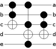
Current decomposition algorithms may lead to non-optimal circuits with respect to NNC. As an example, Fig. 3 (a) shows the standard decomposition of a Toffoli gate leading to an NNC value of 1. The general idea of our NNC optimization is to apply adjacent SWAP gates whenever a non-adjacent quantum gate occurs in the standard decomposition. More precisely, SWAP gates are added in front of each gate with non-adjacent control and target lines to “move” a control (target) line of towards the target (control) line until they become adjacent. Afterwards, SWAP gates are added to restore the original ordering of circuit lines. In total, this leads to additional quantum cost given by the following lemma:
Lemma 1
Consider a quantum gate where its control and target are placed at the and lines, respectively. Using adjacent SWAP gates as proposed, additional quantum cost of are needed.
-
Proof ()
In total, adjacent SWAP operations are required to move the control line to the target, so that both become adjacent. Another SWAP operations are needed to restore the original ordering. Considering quantum cost of 3 for each SWAP operation, this leads to the additional quantum cost of .
By applying this method consecutively to each non-adjacent gate, a quantum circuit with NNC of 0 can be determined in linear time.
Example 1
Consider the standard decomposition of a Toffoli gate as depicted in Fig. 3 (a). As can be seen, the first gate is non-adjacent. Thus, to achieve NNC-optimality, SWAP gates in front and after the first gate are inserted (see Fig. 3 (b)). Since each SWAP gate requires 3 quantum gates, this increases the total quantum cost to but leads to an NNC value of 0.
In the rest of this paper, this method is denoted by naive NNC-based decomposition. Obviously, this straightforward method leads to a high increase in quantum cost. In the next section, more elaborated approaches for synthesizing NNC-optimal circuits are proposed.
5 Improvements
Two improved approaches for NNC-optimal generation of quantum circuits from reversible logic are introduced. The first one exploits exact synthesis techniques while the second one manipulates the circuit and specification, respectively.
5.1 Exploiting Exact Synthesis
A few exact synthesis methods for quantum and reversible circuits have been recently introduced that generate quantum circuits with minimal quantum cost (for examples see [27, 13]). In this section, we propose a synthesis algorithm to construct quantum circuits with both minimal quantum cost and minimal NNC.
The developed approach is similar to the one introduced in [13]. Here, the synthesis problem is expressed as a sequence of Boolean satisfiability (SAT) instances. For a given function , it is checked if a circuit with gates realizing exists. Thereby, is initially assigned to and increased in each iteration if no realization is found.
More formally, for a given and a reversible function , the following SAT instance is created:
where
-
•
is a Boolean vector representing the inputs of the network to be synthesized for truth table line ,
-
•
is a Boolean vector representing the outputs of the network to be synthesized for truth table line , and
-
•
is a set of constraints representing the synthesis problem for a given gate library.
The difference in comparison to [13] is, that the constraints in do not represent the whole set of elementary quantum gates. In fact, a restricted gate library with only adjacent gates is applied.
Although solving the generated SAT instances using a modern SAT solver can produce optimized circuits, the applicability of such an exact method is always limited to relatively small functions due to the exponential search space. In this sense, the proposed method is sufficient to construct minimal realizations with respect to both quantum cost and NNC for a set of Toffoli and Peres gate configurations as shown in Table 3.
But nevertheless, these results can be exploited to improve the naive NNC-based decomposition. Once an exact NNC-optimal quantum circuit for a reversible gate is available (denoted by macro in the following), it can be reused as shown by the following example:
Example 2
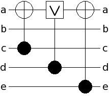
Reconsider the decomposition of a Toffoli gate as depicted in Fig. 3. Using the proposed exact synthesis approach, a minimal quantum circuit (with respect to both quantum cost and NNC) as shown in Fig. 3(c) is determined444The circuit is minimal with respect to the underlying gate library introduced in Section 2.2. If another library is applied (e.g. [28]), better realizations may be possible.. In comparison to the naive method (see Fig. 3(b)), this reduces the quantum cost from 11 to 9 while still ensuring NNC optimality. Furthermore, the realization can be reused as a macro while decomposing larger reversible circuits. For example, consider the circuit shown in Fig. 4. Here, for the second gate the naive method is applied (i.e. standard decomposition is performed and SWAPs are added), while for the remaining ones the obtained macro is used. This enables a quantum cost reduction from 96 to 92.
In total, we generated 13 macros as listed in Table 3 together with the respective costs in comparison to the costs obtained by using the naive method. As can be seen, exploiting these macros reduces the cost for each gate by up to 63%. Besides that, also further macros (e.g. known from literature) can be additionally applied. The effect of these macros on the decomposition of reversible circuits is considered in our experiments in Section 6 in detail.
| Macro | Cost | Impr | ||
|---|---|---|---|---|
| Naive | Exact | |||
| 3 | P({a,b},c), P({c,b},a) | 12 | 8 | 33% |
| 3 | P({a,c},b), P({c,a},b) | 24 | 12 | 50% |
| 4 | P({a,b},d), P({d,c},a) | 30 | 11 | 63% |
| 3 | t2({a,b},c), t2({c,b},a) | 11 | 9 | 18% |
| 4 | t2({a,b},d), t2({d,c},a) | 29 | 12 | 59% |
| 3 | t2({a,c},b) | 17 | 13 | 24% |
| 4 | t2({d,b},a), t2({a,c},d) | 29 | 13 | 55% |
5.2 Reordering Circuit Lines
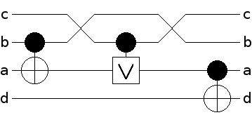
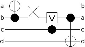
Applying the approaches introduced so far leads to an increase in the quantum cost for each non-adjacent gate. In contrast, by modifying the ordering of the circuit lines, some of the additional costs can be saved. As an example, consider the circuit in Fig. 5(a) with quantum cost 3 and an NNC value of 6. By reordering the lines as shown in Fig. 5(b), the NNC value can be reduced to 1 without increasing the total quantum cost. It is worth noting that manipulating the line order has been previously done to reduce the quantum cost e.g. in [8, 29]. To determine which lines should be reordered, two heuristic methods are proposed in the following. The former one changes the ordering of the primary inputs and outputs according to a global view while the latter one applies a local view to assign the line ordering.
5.2.1 Global Reordering
After applying the standard decomposition introduced in Section 2.2, a cascade of 1- and 2-qubit gates is generated. Now, an ordering of the circuit lines which reduces the total NNC value is desired. To do that, the “contribution” of each line to the total NNC value is calculated. More precisely, for each gate with control line and target line , the NNC value is determined. This value is added to variables and which are used to save the impacts of the circuit lines and on the total NNC value, respectively. Next, the line with the highest NNC impact is chosen for reordering and placed at the middle line (i.e. swapped with the middle line). If the selected line is the middle line itself, a line with the next highest impact is selected. This procedure is repeated until no better NNC value is achieved. Finally, SWAP operations as described in the previous sections are added for each non-adjacent gate.
Example 3
Consider the circuit depicted in Fig. 6(a). After calculating the NNC contributions, we have , , , and . Thus, lines (highest impact) and (middle line) are swapped. Since further swapping does not improve the NNC value, reordering terminates and SWAP gates are added for the remaining non-adjacent gates. The resulting circuit is depicted in Fig. 6(b) and has quantum cost of 9 in comparison to 21 that results if the naive method is applied.
5.2.2 Local Reordering
In order to save SWAP gates, line ordering can also be applied according to a local schema as follows. The circuit is traversed from the inputs to the outputs. As soon as there is a gate with an NNC value greater than 0, a SWAP operation is added in front of to enable an adjacent gate. However, in contrast to the naive NNC-based decomposition, no SWAP operation is added after . Instead, the resulting ordering is used for the rest of the circuit (i.e. propagated through the remaining circuit). This process is repeated until all gates are traversed.
Example 4
Reconsider the circuit depicted in Fig. 6(a). The first gate is not modified since it has an NNC of 0. For the second gate, a SWAP operation is applied to make it adjacent. Afterwards, the new line ordering is propagated to all remaining gates resulting in the circuit shown in Fig. 6(c). This procedure is repeated until the whole circuit has been traversed. Finally, again a circuit with quantum cost of 9 (in contrast to 21) results.
6 Experimental Results
In this section, experimental results are presented. We evaluated the methods introduced in Section 4 and Section 5, respectively, by measuring the overhead needed to synthesize circuits with an optimal NNC value of 0. The proposed approaches have been implemented in C++ and applied to the benchmark circuits available at RevLib [30]. All experiments have been carried out on an AMD Athlon 3500+ with 1 GB of main memory.
The results are shown in Table 4. The first column gives the names of the circuits followed by unique identifiers as used in RevLib. Then, the number of circuit lines (n), the gate count (gc), the quantum cost (qc), and the NNC value of the original (reversible) circuits are shown. The following columns denote the quantum cost of the NNC-optimal circuits obtained by using the naive method (Naive), by additionally exploiting macros (+Macros), and by applying reordering as described in Section 5.2 (Global, Local, or both), respectively. The next column gives the percentage of the best quantum cost reduction obtained by the improvements in comparison to the naive method (Best Imprmnts). The last column shows the smallest overhead in terms of quantum cost needed to achieve NNC-optimality in comparison to the original circuit (Overhead to achieve NNC optimality). All run-times are negligible (i.e. less than one minute) and are omitted in the table.
-
Benchmark Original Circuit Decomposed (NNC-optimal) Circuits Overhead to Reordering Best achieve NNC Naive +Macros Global Local Glob.+Loc. Imprmnts optimality n gc qc NNC qc qc qc qc qc 0410184_169 14 46 90 24 234 197 234 423 423 16% 2,19 3_17_13 3 6 14 3 32 28 32 32 32 13% 2,00 4_49_17 4 12 32 21 158 120 128 98 98 38% 3,06 4gt10-v1_81 5 6 34 41 282 282 258 150 147 48% 4,32 4gt11_84 5 3 7 7 49 47 25 22 16 67% 2,29 4gt12-v1_89 5 5 42 80 525 525 321 171 168 68% 4,00 4gt13-v1_93 5 4 16 26 173 173 77 56 53 69% 3,31 4gt4-v0_80 5 5 34 55 366 364 168 138 141 62% 4,06 4gt5_75 5 5 21 20 142 138 118 82 79 44% 3,76 4mod5-v1_23 5 8 24 25 174 155 114 78 78 55% 3,25 4mod7-v0_95 5 6 38 36 256 256 352 127 121 53% 3,18 add16_174 49 64 192 95 762 473 762 1104 1104 38% 2,46 add32_183 97 128 384 191 1530 953 1530 3744 3744 38% 2,48 add64_184 193 256 768 383 3066 1913 3066 13632 13632 38% 2,49 add8_172 25 32 96 47 378 233 378 360 360 38% 2,43 aj-e11_165 4 13 45 39 280 260 280 181 181 35% 4,02 alu-v4_36 5 7 31 35 242 238 218 113 104 57% 3,35 cnt3-5_180 16 20 120 416 2621 2591 1457 731 728 72% 6,07 cycle10_2_110 12 19 1126 3368 21420 21420 21420 8046 8046 62% 7,15 decod24-v3_46 4 9 9 9 63 63 39 21 24 67% 2,33 ham15_108 15 70 453 2506 15494 15390 14030 2627 2588 83% 5,71 ham7_104 7 23 83 158 1035 1027 657 342 333 68% 4,01 hwb4_52 4 11 23 14 107 83 107 65 65 39% 2,83 hwb5_55 5 24 104 119 823 817 595 337 340 59% 3,24 hwb6_58 6 42 142 193 1304 1160 1268 614 545 58% 3,84 hwb7_62 7 331 2325 4236 27967 27869 25939 13390 12955 54% 5,57 hwb8_118 8 633 14260 28803 187272 186880 182196 87495 87498 53% 6,14 hwb9_123 9 1959 18124 47373 304659 304540 302481 124068 124041 59% 6,84 mod5adder_128 6 15 83 154 1011 978 675 330 333 67% 3,98 mod8-10_177 5 14 88 147 975 969 621 372 363 63% 4,13 plus127mod8192_162 13 910 57400 165415 1057946 1057804 1057946 503516 503516 52% 8,77 plus63mod4096_163 12 429 25492 63732 407926 407784 407926 210400 210400 48% 8,25 plus63mod8192_164 13 492 32578 99482 633994 633852 633994 279016 279016 56% 8,56 rd32-v0_67 4 2 10 5 38 19 20 32 20 50% 1,90 rd53_135 7 16 77 124 822 750 702 330 303 63% 3,94 rd73_140 10 20 76 119 790 739 646 304 295 63% 3,88 rd84_142 15 28 112 234 1516 1465 1696 556 586 63% 4,96 sym9_148 10 210 4368 12184 77556 77556 67428 20643 25023 73% 4,73 sys6-v0_144 10 15 67 96 638 587 842 263 308 59% 3,93 urf1_149 9 11554 57770 122802 794582 735170 659150 238475 238490 70% 4,13 urf2_152 8 5030 25150 45338 297178 276882 297178 101683 101683 66% 4,04 urf3_155 10 26468 132340 331578 2121808 2038584 1933372 596368 596371 72% 4,51 urf5_158 9 10276 51380 114784 740084 706412 667484 208709 208706 72% 4,06 urf6_160 15 10740 53700 239034 1487904 1478080 1334916 320412 320409 78% 5,97
As can be seen, decomposing reversible circuits to have NNC-optimal quantum circuits is costly. Using the naive method, the quantum cost increases by one order of magnitude on average. However, this can be significantly improved if macros or reordering are applied. Even if reordering may worsen the results in some few cases (e.g. for local reordering in 0410184_169 or add64_184), in total this leads to an improvement of 50% on average – in the best case 83% improvement was observed. Furthermore, since all execution times are negligible, it is feasible to run all decomposition methods and afterwards choose the best circuit as marked bold. As a result, NNC-optimal circuits can be synthesized with a moderate increase of quantum cost.
7 Conclusions and Future Work
In this work, we examined the synthesis of reversible functions with respect to cost metrics beyond gate count and quantum cost. While most of the previous synthesis approaches only take gate count and quantum cost into account, we showed how the evaluation differs if other realistic metrics are applied. Furthermore, by considering NNC as a cost metric for the linear nearest neighbor quantum architecture, we illustrated how the available synthesis flows can be modified to produce NNC-optimal circuits. Improvements were suggested that reduce the quantum cost of the results by up to 83% (56% on average) without affecting the NNC-optimality.
For future work, synthesis approaches should be modified with respect to further cost metrics. In particular, quantum-related metrics concurrency and gate distribution have not been addressed by synthesis approaches so far. Therefore, consideration of these metrics is seen as our natural next step. For this purpose, applying exact approaches and line reordering methods similar to those proposed in the paper may be useful.
Acknowledgment
Parts of this research work has been supported by the German Research Foundation (DFG) (DR 287/20-1).
References
- [1] R. Landauer. Irreversibility and heat generation in the computing process. IBM Journal of Research and Development, 5:183–191, July 1961.
- [2] C. Bennett. Logical reversibility of computation. IBM Journal of Research and Development, 17(6):525–532, November 1973.
- [3] G. Schrom. Ultra-Low-Power CMOS Technology. PhD thesis, Technischen Universitat Wien, June 1998.
- [4] B. Desoete and A. De Vos. A reversible carry-look-ahead adder using control gates. Integration. The VLSI Journal, 33(1):89–104, 2002.
- [5] M. Nielsen and I. Chuang. Quantum Computation and Quantum Information. Cambridge University Press, 2000.
- [6] D. Maslov. Linear depth stabilizer and quantum fourier transformation circuits with no auxiliary qubits in finite neighbor quantum architectures. Physical Review A, 76, 2007.
- [7] M. Ross and M. Oskin. Quantum computing. Commun. ACM, 51(7):12–13, July 2008.
- [8] D. Maslov, G. W. Dueck, and D. Michael Miller. Toffoli network synthesis with templates. IEEE Trans. on CAD, 24(6):807–817, 2005.
- [9] D. Maslov, G. W. Dueck, and D. M. Miller. Techniques for the synthesis of reversible toffoli networks. ACM Trans. Des. Autom. Electron. Syst., 12(4):42, 2007.
- [10] M. Saeedi, M. Sedighi, and M. Saheb Zamani. A novel synthesis algorithm for reversible circuits. IEEE/ACM International Conference on Computer-aided design, pages 65–68, 2007.
- [11] P. Gupta, A. Agrawal, and N.K. Jha. An algorithm for synthesis of reversible logic circuits. IEEE Trans. on CAD, 25(11):2317–2330, 2006.
- [12] D. Große, R. Wille, G.W. Dueck, and R. Drechsler. Exact multiple control toffoli network synthesis with SAT techniques. IEEE Trans. on CAD, 28(5):703–715, 2009.
- [13] D. Große, R. Wille, G. W. Dueck, and R. Drechsler. Exact synthesis of elementary quantum gate circuits for reversible functions with don’t cares. International Symposium on Multiple Valued Logic, pages 214–219, 2008.
- [14] R. Wille and R. Drechsler. Effect of BDD optimization on synthesis of reversible and quantum logic. Workshop on Reversible Computation, 2009.
- [15] A. G. Fowler, S. J. Devitt, and L. C. L. Hollenberg. Implementation of shor’s algorithm on a linear nearest neighbour qubit array. Quant. Info. and Comput., 4:237–245, 2004.
- [16] S. A. Kutin. Shor’s algorithm on a nearest-neighbor machine, 2006.
- [17] T. Toffoli. Reversible computing. In Automata, Languages and Programming, page 632. Springer, 1980. Technical Memo MIT/LCS/TM-151, MIT Lab. for Comput. Sci.
- [18] E. F. Fredkin and T. Toffoli. Conservative logic. International Journal of Theoretical Physics, 21(3/4):219–253, 1982.
- [19] A. Peres. Reversible logic and quantum computers. Physical Review, 32:3266–3276, 1985.
- [20] T. Simonite. Error-check breakthrough in quantum computing. New Scientist, June 8 2006.
- [21] D-wave systems. http://www.dwavesys.com/, 2007.
- [22] V. V. Shende, S. S. Bullock, and I. L. Markov. Synthesis of quantum-logic circuits. IEEE Trans. on CAD, 25(6):1000–1010, June 2006.
- [23] A. Barenco et al. Elementary gates for quantum computation. Physical Review, 52:3457–3467, 1995.
- [24] D. Maslov, C. Young, D. M. Miller, and G. W. Dueck. Quantum circuit simplification using templates. Design, Automation and Test in Europe, pages 1208–1213, March 2005.
- [25] M. K. Thomson and R. Glück. Optimized reversible binary-coded decimal adders. Journal of Systems Architecture: the EUROMICRO Journal, 54(7):697–706, 2008.
- [26] R. V. Meter and M. Oskin. Architectural implications of quantum computing technologies. J. Emerg. Technol. Comput. Syst., 2(1):31–63, 2006.
- [27] W. N. N. Hung, X. Song, G. Yang, J. Yang, and M. Perkowski. Optimal synthesis of multiple output boolean functions using a set of quantum gates by symbolic reachability analysis. IEEE Trans. on CAD, 25(9):1652–1663, September 2006.
- [28] G. Song and A. Klappenecker. The simplified toffoli gate implementation by margolus is optimal. Quant. Info. and Comput., 4:361–372, 2003.
- [29] R. Wille, D. Große, G. W. Dueck, and R. Drechsler. Reversible logic synthesis with output permutation. International Conference on VLSI Design, pages 189–194, 2009.
- [30] R. Wille, D. Große, L. Teuber, G. W. Dueck, and R. Drechsler. Revlib: An online resource for reversible functions and reversible circuits. International Symposium on Multiple Valued Logic, pages 220–225, May 2008.