Aggregate AP Throughputs for Long File Transfers in a WLAN controlled by Inhomogeneous TCP Connections
Abstract
The performance analysis of long file TCP controlled transfers in a WLAN in infrastructure mode is available in the present literature with one of the main assumptions being equal window size for all TCP connections. In this paper, we extend the analysis to TCP-controlled long file uploads and downloads with different TCP windows. Our approach is based on simple Markov chain given in the paper [1], [2] with arbitrary window sizes. We presented simulation results to show the accuracy of the analytical model.
Index Terms:
WLAN, Access Points, Infrastructure Mode, Uploading and Downloading, TCP window.I Introduction
This paper is concerned with infrastructure mode WLANs that use the IEEE 802.11 DCF mechanism. We are interested in analytical models for evaluating the performance of TCP-controlled simultaneous uploads and downloads where each connection has arbitrary TCP windows size. A detailed analysis of the aggregate throughput of TCP download in a WLAN for a single rate Access Point (AP) is given in [1] by assuming constant TCP windows for all the links. Similarly aggregate throughput of the AP is evaluated for the multi rate cases are in [2] and [3]. However these works also consider either only download or upload with constant windows. Here, we consider both uploads and downloads along with different TCP windows.
We are motivated to study an analytical model for this scenario because of the clear understanding that it gives, and the useful insights that it can provide on the networks. The closed-form expression or numerical calculation procedures are useful because other features and capability can be built upon them. One such application, which we are studying now, is to utilize the results reported here in devising a improved AP-STA association policy and improving the performance of the system. Similarly if we can estimate the average upload and download throughput for the AP as well as STAs.
Our approach is to model the number of STAs with ACKs and data packets in their MAC queues as an embedded Discrete Time Markov Chain (DTMC), embedded at the instants of successful transmission events. We consider a successful transmission from the AP as a reward. This leads to viewing the aggregate TCP throughput in the frame work of Renewal Reward theory given in [4] .
Our Contribution: We provide a simple approach to improve model of the aggregate throughput of the AP for long-lived TCP connection in terms of both upload and download traffic with arbitrary maximum TCP receive window size in IEEE 802.11 networks. We use the basic model and results presented in [1]. We show that numerical results of our analytical model compare well with the simulation results. Simulations indicate that for the upload-download traffic scenario, our numerical evaluation of the analytical expression matches accurately with maximum error of 0.76 % .
This paper is organized as follows: Section II outlines related literature. In Section III we state the system model and we discuss the modelling assumptions. In Section IV we develop throughput analysis. In Section V, we present performance evaluation results. In Section VI we discuss the results. Finally, the paper concludes in Section VII.
II Related Work
The analytical work on this research area have been studied, considering saturated and unidirectional traffic, i.e, either uplink or downlink in [5], [6] and [7] . All the above papers assume that all the STAs are saturated, in other words they have all the time packets to send to the AP. Our work deviates from this assumption. We consider the system with actual traffic load like TCP.
All the related work that we are aware of assumes homogeneous TCP connections in the sense that the maximum window size is the same for all connections. [1] and [8] propose a model for single rate AP-STA WLAN assuming the same maximum size of TCP window for all TCP connections. An extension of this work in [2] considers two rates of association with long file uploads from STAs to a local server and multirate case in [3]. [9] and [10] present another analysis of scenario of upload and download TCP-controlled file transfers with UDP traffic in a single cell infrastructure WLAN. They assumed equal TCP maximum window size for all connections, that TCP receivers use undelayed ACKs, and showed that the total TCP throughput is independent of the number of STAs in the system. Also, upload and download transfers obtain an equal share of the total throughput of the AP. The letter [11], gives the average value analysis of TCP performance with upload and download traffic. First they provide expression for average number of active TCP stations. In [12], finite buffer AP with TCP traffic in both upload and download direction is analysed with delayed and undelayed ACK cases.
[13] provides an analysis for a given number of STAs and maximum TCP receive window size by using well known persistent model proposed in [7]. However this [13] considers only download traffic or upload traffic, not both together.
Another analysis HTTP traffic is in [14], a queuing model is proposed to compute the mean session delay in the presence of short-lived TCP flows and studied the impact of TCP maximum congestion window size on this delay. The analysis also extended to consider the delayed ACK technique.
III System Model
We consider a WLAN which has STAs associated with an AP as shown in Figure 1, and all the M STAs are associated at the same rate. We consider only TCP traffic. STAs are the senders in TCP uplink connections and STAs are receivers in TCP downlink connections. Thus, the AP sends either TCP ACK packets to the uploading STAs or TCP data packets to downloading STAs. The arrows in Figure 1 show the direction of the data packets in the network. These are TCP links, there is also feedback traffic consisting of TCP-ACK packets 111We recall that every TCP receiver advertises a maximum window size. In the absence of packet loss, a TCP sender’s window will grow up to this advertised window. We assume that is large. We will show later how big needs to be for our results to be applicable.
Let the cumulative TCP advertised window size of all downloading STAs and the cumulative TCP advertised window size seen by all uploading STAs. Let the sum of the maximum size of the TCP windows. All the nodes contend for the channel using the DCF mechanism as given in IEEE 802.11. We assume that there are no link errors. Packets in the medium are lost only due to collisions. Because of the long file transfer scenario, we can assume that TCP sources are operating in Congestion Avoidance. Hence TCP startup transients can be ignored. Further, we assume that all the nodes use the RTS CTS mechanism while sending data packets and use basic access to send ACK packets. As soon as the station receives a data packet, it generates an ACK packet without any delay and it is enqueued at the MAC layer for transmission. We assume that all nodes have sufficiently large buffers, so that packets are not lost due to buffer overflow. Also, TCP timeouts do not occur. The value of RTT is very small, since files are downloaded from a server located on the LAN as shown in Figure 1.
Thus, several TCP connections exist simultaneously and every station including the AP contends for the channel. Since no preference is given to the AP, and it has to serve all STAs, the AP becomes a bottleneck, and it is modelled as being backlogged permanently. The aggregate throughput of the AP is shared among all stations.

IV Analysis
The probability that the AP sends a TCP data packet to a downloading STA is which is equal to the ratio of the cumulative advertised window for downloading connections (which we refer to as the “cumulative download window” henceforth), to the sum of the cumulative download and upload windows. Similarly, the probability the AP sends a TCP-ACK packet to an uploading STA is which is again, the ratio of the cumulative upload window, to the sum of the cumulative download and upload windows. i.e , and .
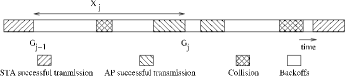
Figure 2 shows one possible sample path of the events on the wireless channel in the WLAN. The random epochs indicate the end of the successful transmission from either the AP or one of the stations. We observe that most STAs have empty MAC queues, because, in order for many STAs to have TCP-ACK packets or TCP data packets, the AP must have had a long run of successes in the channel contention – and this is unlikely because no special priority is given to the AP. So when the AP succeeds in transmitting, the packet is likely to be for a STA with an empty MAC queue.
Let be the number of STAs with nonempty MAC queues: if the STA is downloading, it has an ACK packet to send, or if it is uploading, then it has a TCP data packet to be sent. If there are nonempty STAs and a nonempty AP, each nonempty WLAN entity attempts to transmit with probability , where is the channel access probability under saturation with WLAN entities as in [6]. So evolves as a DTMC over the epochs . This allows us to consider as a Markov Renewal Sequence, and as a semi-Markov process. We have the DTMC which is shown in Figure 3; transition probabilities are indicated as well. By inspection, we can say that the DTMC is irreducible. The Detailed Balanced Equation holds for properly chosen set of equilibrium probabilities. The detailed balanced equation (DBE) is

| (1) |
Here, is the stationary distribution of the DTMC. From the set of equations given in (1) and , the stationary distribution is
| (2) |
Let be the sojourn time in a state .
Conditioning on various events (idle slot, collision or successful
transmission) that can happen in the next time slot, the
following expression for the mean cycle length can be written
| (3) |
In the above expression (3), is the probability of the slot being idle. is the probability that the AP wins the contention and transmits the data packet or TCP-ACK packet. is the average time spent by the AP in a successful transmission; we have
is the time taken by the AP or STA to transmit a data packet and is the time taken by the AP or STA to transmit an ACK packet.
Detailed expressions and explanations are provided in the Appendix. In the above expression when two or more transmission attempts occur, we have a collision. The duration of the collision () is given by the duration of the longest transmission time, i.e., the lowest rate of transmission determines the duration of collision. The duration of the collision is decided by either the duration of RTS transmission or duration of TCP-ACK packet, depending on the physical rates.
Let denote the duration of a collision given that the RTS is the longest packet involved in the collision. Then we have
where the notation is defined in Table V Similarly, let denote the duration of a collision given that the TCP-ACK is the longest packet involved in the collision. We have
From Table V in Appendix (see also table of parameters in [12]) in the above equation, it is clear that value of data rate and control rate decides the duration of collisions as follows. if the data rate is 11 Mbps and if the data rate is 5.5 Mbps or 2 Mbps. The various possibilities of collisions can now be listed as follows.
In the first case, equals under two conditions: (i) AP data packet transmission collides with either uploading or downloading STA (ii) AP TCP-ACK packet transmission collides with uploading STA. In the second case, equals when AP TCP-ACK packet transmission collides with downloading STA Further explanation is given in Table IV in Appendix.
In the above expression, various probabilities have been obtained by considering the events and using channel access probability , when there are contending nodes.
From Equation (3) we have
| (4) |
Calculations of probabilities and times in (4) are shown in the Appendix. The mean reward for a cycle is obtained as follows. We are interested in finding the long run time average of successful transmissions from the AP. This leads to Markov regenerative analysis or the renewal reward theorem approach. To get the mean renewal cycle length, we can use the mean sojourn time given in Equation (4). The mean reward in a cycle can be obtained as follows. A reward of 1 is earned when the AP transmits either a TCP data packet or an ACK packet successfully by winning the channel. The probability of the AP winning the channel is . Hence the semi Markov process exits the state with probability . A reward of 0 is earned with the probability . Therefore, the expected reward is . So this results in aggregate throughput of the AP with both upload and download.
Hence the aggregate TCP throughput in this case can be
calculated as
| (5) |
Further, we can consider only upload throughput or download throughput by changing the assignment of rewards. If we count a reward of 1 when the AP transmits only TCP data packet and reward of 0 else (even though the AP wins the channel and transmits TCP Ack packet), we can obtain the aggregate download throughput . Similarly, if we count a reward of 1 when the AP transmits a TCP-ACK packet, we can get aggregate upload throughput .
V Evaluation
To verify the accuracy of the model, we performed experiments using the Qualnet 4.5 network simulator [15]. We considered 802.11b physical data rates as 11, 5.5 and 2 Mbps. In Table I, results are given for a few cases of this scenario, i.e. with different number of stations having different maximum size of TCP receive windows. Table I gives the number of downloading and uploading STAs with TCP window sizes being 24, 20 and 14 packets, and the data rates being 11, 5.5 and 2 Mbps. Analytically calculated aggregate throughputs are listed against simulation results with 95% confidence intervals for 30 runs in the right side columns of Table I.
| Rate | No.of STAs with windows size | Aggregate | ||||||
| Mbps | Downloading | Uploading | Throughput [Mbps] | |||||
| 24 | 20 | 16 | 24 | 20 | 16 | Analysis | Simulation | |
| 11 | 1 | 2 | 3 | 4 | 2 | 3 | 4.38 | 4.37 0.01 |
| 2 | 1 | 3 | 4 | 2 | 3 | 4.38 | 4.37 0.01 | |
| 5.5 | 3 | 2 | 1 | 4 | 2 | 3 | 3.04 | 3.04 0.01 |
| 4 | 3 | 2 | 1 | 3 | 2 | 3.04 | 3.04 0.01 | |
| 2 | 3 | 2 | 4 | 3 | 1 | 2 | 1.5 | 1.5 0.001 |
| 3 | 2 | 4 | 3 | 2 | 1 | 1.5 | 1.5 0.001 | |
In 802.11g, data rates are 54, 48, 36, 24, 18, 12 and 6 Mbits/s. Qualnet 4.5, is configured to this mode by setting the channel frequency for 802.11a radio as 2.4 GHz. In Table II, comparisons between analytical and simulation values are given for selected data rates to illustrate the accuracy of the analytical model. The values of maximum TCP receive windows are shown in the heading of the table as 24, 20 and 16 packets. Number of STAs with these as TCP windows are listed for both upload and download links. The rights side columns give aggregate throughput for the different values of data rates. Simulation results presented with 95% confidence interval for 30 runs.
| Rate | No.of STAs with windows size | Aggregate | ||||||
| Mbps | Downloading | Uploading | Throughput [Mbps] | |||||
| 24 | 20 | 16 | 24 | 20 | 16 | Analysis | Simulation | |
| 54 | 1 | 2 | 3 | 4 | 2 | 3 | 22.61 | 22.5 0.01 |
| 4 | 1 | 2 | 2 | 1 | 3 | 22.61 | 22.56 0.01 | |
| 48 | 3 | 2 | 1 | 4 | 2 | 3 | 19.68 | 19.54 0.01 |
| 4 | 3 | 2 | 1 | 3 | 4 | 19.68 | 19.53 0.01 | |
| 36 | 3 | 2 | 1 | 4 | 2 | 3 | 14.94 | 14.92 0.01 |
| 4 | 3 | 2 | 1 | 3 | 2 | 14.94 | 14.92 0.01 | |
| 12 | 3 | 2 | 4 | 3 | 1 | 2 | 5.16 | 5.15 0.001 |
| 3 | 2 | 1 | 3 | 2 | 4 | 5.16 | 5.14 0.001 | |
As discussed in Section IV, the aggregate throughput of the AP is divided between aggregate upload and download in proportion to their maximum TCP receive window sizes. The numerical evaluation of Equation (5) is given in Table III for all, i.e., download upload and aggregate throughput along with simulation results with 95% confidence interval for 30 runs.
| Rate | AP Download | AP Upload | ||
|---|---|---|---|---|
| Mbps | Throughput [Mbps] | Throughput [Mbps] | ||
| Analysis | Simulation | Analysis | Simulation | |
| 54 | 8.56 | 8.51 0.01 | 13.987 | 14.055 0.01 |
| 12.68 | 12.65 0.01 | 9.935 | 9.9127 0.01 | |
| 48 | 8.074 | 8.016 0.01 | 11.524 | 11.606 0.01 |
| 11.011 | 10.94 0.01 | 8.603 | 8.6686 0.01 | |
| 36 | 6.13 | 6.12 0.01 | 8.799 | 8.812 0.01 |
| 9.24 | 9.23 0.01 | 5.693 | 5.701 0.01 | |
| 12 | 3.027 | 3.021 0.001 | 2.127 | 2.133 0.001 |
| 2.173 | 2.164 0.001 | 2.976 | 2.987 0.001 | |
VI Discussion
In this work, we presented an analytical model to obtain the aggregate throughput when several TCP-controlled long file upload and downloads are going on with arbitrary window sizes. Calculation of probabilities and durations of all the events need to consider physical data rates and control rates. The analysis of throughput made use of only the fact that the TCP source operates in Congestion Avoidance.
We can notice that in Tables I and II, for a specified data rate and control rate of transmission, there is no discrepancy in the aggregate throughput (both upload and download) with the number of STAs. It motivates us to use this model as a processor sharing model for arbitrarily arriving short file transfers. Every downloading STA will receive the service rate of (for uploading STA, ) as mentioned in [12]. In our simulation and numerical evaluation we used the 802.11b and 802.11g standards. However, our mathematical expressions are independent of these standards; hence the model can be applied to any other standard that has different number of physical data rates. We assumed no packet losses and no channel errors; we need to address these by introducing link error probability. Also we assumed that RTT is negligible, which needs to be generalized.
VII Conclusion
This paper developed a simple general analytical framework to obtain accurate closed-form expressions for the performance of the AP with long-lived TCP connections in IEEE 802.11 networks. In this work, we have presented a model for the aggregate throughput of the AP by considering simultaneous TCP upload and download traffic for long files with arbitrary TCP window sizes. We verified the correctness of the analytical model with the simulation results. These results show the accuracy of the model, with the maximum error being 0.76 % . We considered single data rate of association. This approach can be extended to multiple rates but this makes the model more complicated and consequent state space expansion makes the calculation of stationary probability distribution tedious. This is a particular limitation of our approach. However the model can be used in addressing other performance evaluation questions of WLANs.
[ Expressions for probabilities and times discussed in section IV ]
| is the probability of the slot being idle. | |
| is probability of AP wins the contention and | |
| transmits the packet . | |
| is the probability of STA the contention | |
| is the probability of the collision event | |
| is the mean time taken by the AP to send packet (TCP data or TCP-ACK) to an STA | |
| is the duration of transmitting one TCP data packet or one TCP-ACK | |
| packet from STA including overhead | |
| is the collision duration when the AP and | |
| STAs are involved. | |
| is the time taken by any node to transmit an TCP data packet. | |
| is the time taken by any node to transmit an TCP ACK. | |
| Collision | AP(STA) sends Data | AP(STA) sends TCP ACK |
|---|---|---|
| Data rate is 11 Mbps | ||
| Uploading STA | Length of RTS | Length of RTS |
| Downloading STA | Length of RTS | Length of TCP-ACK |
| Data rate is either 2 or 5.5 Mbps | ||
| Uploading STA | Length of RTS | Length of TCP-ACK |
| Downloading STA | Length of TCP-ACK | Length of TCP-ACK |
The values of these parameters are given in Table V
| Parameters | Symbol | 802.11b | 802.11g |
|---|---|---|---|
| Max PHY data rate | 11 Mbps | 54 Mbps | |
| Control rate | 2 Mbps | 6 Mbps | |
| PLCP preamble time | |||
| PHY Header time | |||
| MAC Header size | 34 bytes | 34 bytes | |
| RTS Header size | 20 bytes | 20 bytes | |
| CTS Header size | 14 bytes | 14 bytes | |
| MAC ACK Header size | 14 bytes | 14 bytes | |
| IP Header size | 20 bytes | 20 bytes | |
| TCP Header size | 20 bytes | 20 bytes | |
| TCP ACK Packet size | 20 bytes | 20 bytes | |
| TCP data payload size | 1460 bytes | 1460 bytes | |
| System slot time | |||
| DIFS time | |||
| SIFS time | |||
| EIFS time | |||
| CWmin | CWmin | 31 | 15 |
| CWmax | CWmin | 1023 | 1023 |
References
- [1] G. Kuriakose, S. Harsha, A. Kumar, and V. Sharma, “Analytical models for capacity estimation of IEEE 802.11 WLANs using DCF for Internet applications,” Wireless Networks, 2006.
- [2] Krusheel M and J. Kuri, “Performance Analysis of TCP Uploads in WLANs with Multiple Rates,” NCC 2009.
- [3] Pradeepa BK and J. Kuri, “ Aggregate Download Throughput for TCP-controlled long file transfers in a WLAN with multiple STA-AP association rates” http://arxiv.org/abs/1007.3229
- [4] Anurag Kumar, “Discrete Event Stochastic Processes and Queueing Theory: Lecture Notes for an Engineering Curriculum,” http://www.ece.iisc.ernet.in/ anurag/
- [5] G. Bianchi, “Performance analysis of the IEEE 802.11 distributed coordination function,” IEEE JSAC, vol. 18, no. 3, pp.535–547, Mar. 2000.
- [6] A. Kumar, E. Altman, D. Miorandi, and M. Goyal, “New insights from a fixed point analysis of single cell IEEE 802.11 WLANs,” IEEE/ACM Transactions on Networking, Vol. 15, No 3, pp. 588-601, June 2007.
- [7] F. Cali, M. Conti, and E. Gregori, “Dynamic Tuning of the IEEE 802.11 protocol to achieve a Theoretical Throughput Limit,” IEEE/ACM Transaction On Networking, vol. 8 no. 6 pp. 785-799, Dec 2000
- [8] R. Bruno, M. Conti, and E. Gregori, “Throughput Analysis of TCP clients in Wi-Fi Hot Spot Networks,” Networking 2004, LNCS 2042, pages 626-637, 2004
- [9] R. Bruno, M. Conti, and E. Gregori, “Throughput analysis and measurements in IEEE 802.11 WLANs with TCP and UDP traffic flows,” IEEE Transactions on Mobile Computing, vol.7, no.2, pp. 171-186, Feb. 2008.
- [10] R. Bruno , M. Conti, and E. Gregori, “An accurate closed-form formula for the throughput of long-lived TCP connections in IEEE 802.11 WLANs,” Computer Networks, vol. 52, pp. 199-212, 2008
- [11] R Bruno, M Conti, and E Gregori, “Average value analysis of 802.11 WLANs with persistent TCP flows,” IEEE Communication Letters, vol.13, no.4, Apr. 2009.
- [12] R Bruno, M Conti, and E Gregori, “Modelling finite buffer on TCP traffic over an IEEE 802.11 infrastructure WLAN,” IEEE Communication Letters, vol.13, no.4, Apr. 2009.
- [13] J. Yu, S. Choi, “Modeling and analysis of TCP dynamics over IEEE 802.11 WLAN,” Proceedings of the IFIP WONS,, pp. 154-161 Obergurgl, Austria, 2007.
- [14] D. Miorandi, A. Kherani, E. Altman, “A queueing model for HTTP traffic over IEEE 802. 11 WLANs,” Computer Networks, vol. 50, no. 1, pp. 63-79, 2006.
- [15] Qualnet Simulator, www.scalable-networks.com.