Propagation of Bessel beams from a dielectric to a conducting medium
Abstract
Recently, the use of Bessel beams in evaluating the possibility of using them for a new generation of GPR (ground penetrating radar) systems has been considered. Therefore, an analysis of the propagation of Bessel beam in conducting media is worthwhile. We present here an analysis of this type. Specifically, for normal incidence we analyze the propagation of a Bessel beam coming from a perfect dielectric and impinging on a conducting medium, i.e. the propagation of a Bessel beam generated by refracted inhomogeneous waves. The remarkable and unexpected result is that the incident Bessel beam does not change its shape even when propagating in the conducting medium.
In the last decades, electromagnetic waves have found many practical applications, including ones that are different from their traditional utilization in the field of communications. Among these applications, the detection and characterization of buried objects of a non-metallic nature is of particular interest. In relation to this topic, Bessel beams have recently been considered for evaluating the possibility of using localized waves in GPR systems.
Bessel beams (also known as localized Bessel-X waves) are of great interest in physics because of their characteristics of being non diffracting beams, and due to their implications with regard to the topic of superluminality all .
Apart from these features, their nature of localized waves may make them suitable also for other field of interest, As mentioned previously, the possibility of using Bessel beams in GPR apparatus has recently been considered mug1 . This type of utilization requires a knowledge of the propagation of the beam in conducting, absorbing, media zam .
The aim of this note is to analyze the propagation of a Bessel beam coming from a dielectric medium (air, for example) and impinging at normal incidence into a conducting medium, i.e. the propagation of a Bessel beam generated by refracted inhomogeneous waves. We will demonstrate that, quite surprisingly, the beam does not change its shape when propagating in the conducting medium, but solely attenuates by going far away from the interface.
The following analysis works in the scalar approximation, since it refers to the specific system with specific sources. For this system, it has been demonstrated that, among the three components of the field, there is one which is dominant with respect to the other two. In this situation, the scalar approximation works well, and thus its use is justified mug .
Let us begin by considering a system formed by two half-spaces, 1 and 2, as sketched in Fig. 1.
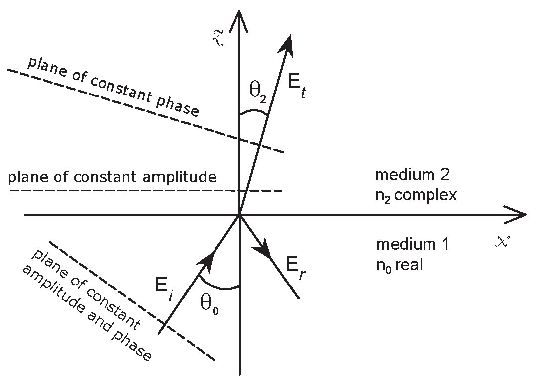
A plane wave coming from medium 1 impinges on medium 2 with the incident angle . Let medium 1 be a perfect dielectric, and medium 2 a conducting medium that is separated from medium 1 by a plane interface. The incident plane wave in medium 1 is
| (1) |
This impinging plane wave is expected to give rise in medium 2 to a plane wave , but of complex type. This is due to the fact that the refractive index in medium 2 is complex, hence an exponential decrease of the real amplitude is expected. Thus in medium 2 we write
| (2) |
where and are the wave numbers in medium 1 (vacuum or air) and in medium 2, respectively; is the transmission coefficient, which can be found by applying the boundary conditions at the interface between the two media; are the real cosine directors of the direction of propagation in medium 1, while are constants only subject to the condition that
| (3) |
For the sake of simplicity, we have taken the amplitude of the incoming wave as being equal to one, and we have omitted the temporal factor . In a system of spherical coordinates, the quantities and may be written as
| (4) | ||||||
In principle, , and could be complex quantities. However, this is not so, as can be inferred by simple physical considerations.
As is well known str ; bor , in the propagation through a plane interface into a conducting medium, the field is described by a system of inhomogeneous equations. Inside the conducting medium the planes of constant amplitude are parallel to the interface, while the planes of constant phase are tilted with respect to the same surface (see Fig. 1). The direction of propagation is determined by the normal to the constant phase-planes.
Now, for our purpose, it is crucial to note that if the planes of constant amplitude are parallel to the interface, then both the products and in Eq. (2) have to be both real, otherwise the constant-amplitude surfaces would be plane, but with an inclination with respect to the interface. Moreover, since the products and are real, is also real, since it is the ratio of two real numbers:
| (5) |
hence, is a real angle.
We have therefore obtained a quite unexpected result: even if the angle of refraction in the conducting medium is complex (as expected) and the refractive index is complex, the product is a real quantity. On this basis, by applying the principle of the continuity of the phase distribution at the interface () between the dielectric and conducting media, we reobtain the Snell law, that is
| (6) |
from which it turns out that is complex: . By solving Eq. (6) we obtain the real and imaginary parts of the complex angle of refraction :
where and are the real and imaginary parts of the refractive index , respectively, and
Coming back to Eq. (2), it is expedient to refer to a cylindrical coordinates system () such that
| (8) |
and
| (9) |
where use has been made of Eq. (6). The quantity controlling the -dependence of the wave is complex:
| (10) |
which indicates that the wave attenuates in the direction normal to the interface (-axis).
Let us now consider a Bessel beam. As is well known, a Bessel beam originates from the interference of an infinite number of plane waves whose directions of propagation make the same angle, say , with a given axis, say . Let us suppose to have such plane waves in medium 1. Therefore, the field propagating in medium 1 is given by the sum of an infinite number of waves like that of Eq. (Propagation of Bessel beams from a dielectric to a conducting medium) and results in
| (11) |
where denotes the zero-order Bessel function of first kind. Similarly, by integrating Eq. (Propagation of Bessel beams from a dielectric to a conducting medium) between 0 and , we are able to obtain the field propagating in medium 2:
| (12) |
In looking at Eqs. (Propagation of Bessel beams from a dielectric to a conducting medium) and (Propagation of Bessel beams from a dielectric to a conducting medium), we arrive at this notable result: a Bessel beam propagating from a perfect dielectric medium to a conducting one does not change its shape during the passage. In other words, apart from an attenuation in the amplitude, no generic Bessel beam - but just the incident beam - is propagated.
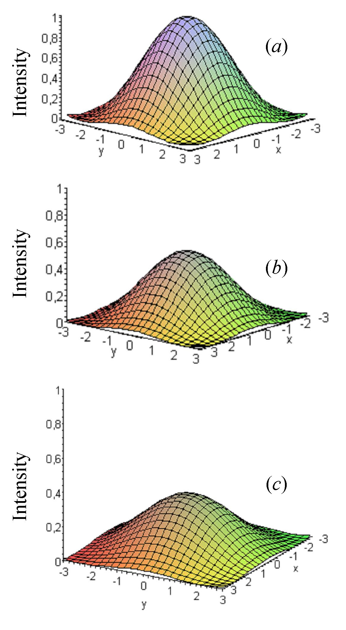
The field in the conducting medium still has the shape of the incident Bessel beam: the maxima, the minima and the zeros of the Bessel function do not change their positions in passing through an infinite number of conducting layers. The effect of the conducting media lies only in the attenuation of the amplitude which suffers some modifications: at the amplitude is not 1 but the complex amplitude , it then attenuates by going away from the interface (see Fig. 2), due to the complex exponential factor.
When the conductivity increases, the planes of constant phase of each wave tend to align themselves parallel to the interface. The effect of the conductivity is to reduce the value of the refraction angle: for large value of the conductivity the angle of refraction tends to zero. In this situation the Bessel beam loses its characteristic of localized wave and tends to become a plane wave. For infinite conductivity there is no propagation, and the field inside the conducting medium is zero: the electromagnetic energy is wholly dissipated by the Joule effect.
References
- (1) The literature is extremely rich as regard these two topics. Since the aim of this note does not involve covering these aspects, we cite only a recent textbook that deals with these topics: Localized Waves, edited by Hugo. E. Hernández-Figueroa, Michel Zamboni-Rached, and Erasmo Recami, Wiley Series in Microwave and Optical Engineering, Hoboken, New Jersey, USA, 2008, and references therein.
- (2) D. Mugnai and P. Spalla, Optics Commun. 282 (2009) 4668.
- (3) Michel Zamboni-Rached, Optics Express 14 (2006) 1804.
- (4) D.Mugnai and I. Mochi, Phys. Rev. E 73 (2006) 016606.
- (5) J. A. Stratton, Electromagnetic Theory, McGraw-Hill, New York, 1941, Sec. 9.8.
- (6) Max Born and Emil Wolf, Principles of Optics, Pergamon Press, New York, 1959, Chap. 13.4.1