Multiple Unicast Capacity of 2-Source 2-Sink Networks
Abstract
We study the sum capacity of multiple unicasts in wired and wireless multihop networks. With source nodes and sink nodes, there are a total of independent unicast sessions (messages), one from each source to each sink node (this setting is also known as an network). For wired networks with arbitrary connectivity, the sum capacity is achieved simply by routing. For wireless networks, we explore the degrees of freedom (DoF) of multihop networks with a layered structure, allowing arbitrary number of hops, and arbitrary connectivity within each hop. For the case when there are no more than two relay nodes in each layer, the DoF can only take values or , based on the connectivity of the network, for almost all values of channel coefficients. When there are arbitrary number of relays in each layer, the DoF can also take the value . Achievability schemes incorporate linear forwarding, interference alignment and aligned interference neutralization principles. Information theoretic converse arguments specialized for the connectivity of the network are constructed based on the intuition from linear dimension counting arguments.
1 Introduction
Capacity characterization for multiple unicasts is one of the most important problems in network information theory. Optimal interference management principles are essential to the multiple unicast problem, both in the wireless setting where interference among concurrent transmissions is an unavoidable property of the propagation medium, as well as in the wired network setting where inter-session network coding gives rise to interference among multiple flows. The study of multiple unicast networks has produced many powerful ideas that embrace interference – such as network coding and interference alignment – and that have shown that the capacity limits can be much higher than possible with conventional interference avoidance approaches that do not allow the mixing of flows, such as routing for wired networks and TDMA/FDMA for wireless networks. The idea of interference alignment has been applied primarily to single hop wireless networks, where it has significantly advanced the understanding of signal dimensions in the form of degrees of freedom (DoF) characterizations. Network coding principles are most well understood in the multicast setting where all messages are desired by all destinations. With a few notable exceptions (including most recently, [1, 2, 3]), the problem of multiple unicasts over multiple hops remains wide open for both wired and wireless networks. In this work our goal is to make progress on this problem, by characterizing the sum capacity and degrees of freedom of multiple unicasts over wired and wireless layered multihop networks, respectively.
1.1 Problem Description
Consider a communication network with distributed source nodes , and distributed sink nodes . A total of independent unicast sessions are possible in this network, one for each source-destination pair. We are interested in the multiple unicast capacity, which we define as the maximum possible sum-rate of all unicast sessions as they simultaneously flow through the network. In more standard information-theoretic terminology, we have independent messages , with messages originating at source and intended for sink , and we wish to find the sum-rate capacity of these messages. Borrowing the corresponding nomenclature from single hop wireless networks [4, 5], we refer to the setting defined above as the user network.
Aside from its significance as the original setting for interference alignment [6, 4], an network is interesting because the sum capacity of an network measures the total amount of information that can flow through the network between a set of distributed sources and a set of distributed destinations without restricting the associations between source-destination pairs. Since each source has an independent message for each destination, all paths that go through the network can carry desired information. However, the total amount of information between the set of sources and the set of destinations is, in general, different from the min-cut between the set of sources and the set of destinations, because of the assumption of distributed sources and distributed destinations, i.e., the sources cannot share messages and destinations cannot jointly process the received signals. For instance, the user network in the single hop wireless setting is shown to have DoF = in [4], while the DoF min-cut outer bound is .
As described above, the distributed nature of sources and destinations and the presence of a desired message from each source to each destination are the defining features of the network setting. The network between the sources and destinations, can be wired or wireless, single or multiple hop. In this work, we will study two different kinds of networks.
-
1.
Wired network: We consider this network in the general setting, i.e., we allow any number of source nodes, any number of destination nodes, any number of hops, and arbitrary network graph topologies comprised of orthogonal noise-free links. Our goal is to characterize the sum-capacity.
-
2.
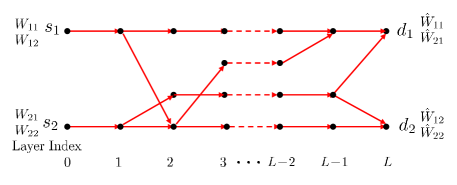
Layered Wireless network: Such a network is illustrated in Fig.1. As shown in the figure, we restrict attention to the multihop wireless setting with a layered structure, i.e., a multihop wireless network, with arbitrary number of layers (hops), an arbitrary number of relay nodes in each layer, and arbitrary connectivity within each hop. Because this is the wireless setting, it incorporates both interference and broadcast features of wireless propagation. Our goal is to characterize the sum DoF.
1.2 Summary of Contribution
The wired network sum-capacity bears a surprisingly simple solution. The sum-capacity is equal to the min-cut separating all sources from all destinations, and is achieved simply by routing. There is no need for interference alignment and there is no need for either intra-session or inter-session network coding. Since the proof is exceedingly simple, we will describe it here.
Suppose we allow all sources to share all messages, and we allow all destinations to share all their received signals. Then we have essentially a single source, single destination network. We know that the min-cut bound is achievable for this network and a routing solution can be found by the Ford Fulkerson algorithm. Since only routing is needed, there is no mixing of information, i.e., there is no need for cooperation among source nodes or among the destination nodes. Thus, the min-cut is also achievable in the wired network with distributed sources and destinations.
The main focus of this paper is on the layered multihop wireless network. Here we proceed in two steps. First, for the case that the number of relay nodes in each layer is no more than 2, we provide an explicit enumeration of all possible network connectivity patterns along with their associated DoF characterizations (in the almost surely sense). In particular, we find that the DoF can only take values . Next we allow arbitrary number of relays in each layer and show that here, in addition to networks with DoF values , there exist networks with DoF . Further, these are the only multiple unicast DoF values possible for all connectivity patterns in a 2-source 2-sink layered multihop wireless network (for almost all values of channel coefficients). In establishing these results, non-trivial achievability arguments make use of the aligned interference neutralization concept introduced earlier in [1]. Non-trivial outer bounds are also needed, e.g., for the DoF = case. The intuition for the information theoretic outer bounds is obtained from linear dimension counting arguments.
It is interesting to contrast the network with the 2 user interference network, since the only difference between the two settings is in the message sets, i.e., both settings can be defined for the same physical network. While the network has 4 independent messages, the interference network has only 2 independent messages. In the one-hop wireless setting, the network is much more interesting than an interference network from a DoF perspective, because the network requires interference alignment, whereas orthogonal access is DoF-optimal for the interference network. In the multi-hop wired setting, the opposite is true. The interference network is interesting because it creates opportunities for network coding (e.g., the famous butterfly network), but the network, as explained earlier in this section, achieves sum-capacity through simple orthogonal access (routing), i.e., requiring neither interference alignment nor network coding. Finally, in the layered multi-hop wireless setting, as it turns out, neither the interference network, nor the network setting is trivial. The DoF of the layered multi-hop interference network are characterized in [2] and are shown to only take values and . We show here that the layered multi-hop network setting presents an even richer picture and gives rise to DoF values and . In both cases, both achievability and converse arguments are non-trivial. For instance, the 2 hop layered network with 2 relays makes use of the idea of aligned interference neutralization, originally introduced in [1], whether it is the interference network or the network. In addition, the layered multihop network gives rise to other cases where aligned interference neutralization is needed, such as the network with DoF.
2 System Model and Definitions
The multihop wireless network we consider in this paper consists of two sources , two destinations and multiple relay nodes between sources and destinations. Each node has one antenna. There are a total of four independent messages in this network, i.e., source wants to send the message to the destination where . We can use a directed graph to characterize the network topology, where and are the sets of nodes and edges, respectively. Such an example is shown in Fig.1. The network has a layered structure. Specifically, for a -hop network, the two sources are at layer 0, the two destinations are at the layer , and the relay nodes at the layer can only receive signals sent from the nodes at the layer, and only transmit to nodes at the layer. In other words, in the graph there are only edges between nodes in adjacent layers. With the layered assumption, we consider an arbitrarily connected network, in the sense that in any two adjacent layers, each node at layer can be arbitrarily connected to the nodes in layer. We also assume that every relay node belongs to at least one directed path from at least one source to at least one destination, because otherwise it can be removed without decreasing the capacity region of the network.
We denote the node in the layer as . The channel coefficient associated with the edge from the node to the node is denoted as . We assume that the channel coefficients are independently drawn from continuous distributions and once drawn, they remain constant during the entire transmission. We also assume that global channel knowledge is available at all nodes. At time index , each node (except the two destinations) transmits a complex-valued signal , which satisfies an average power constraint , for channel uses. The signal received at the node at time is given by
| (1) |
where is the set of the nodes connected to at the layer, and is the i.i.d. additive circularly symmetric complex Gaussian noise with zero-mean unit-variance at the node .
The capacity region of this network is the set of achievable rate tuples where is the SNR, such that each user can simultaneously decode its desired messages with arbitrarily small error probability. The maximum sum rate of this channel is defined as . The capacity in the high SNR regime can be characterized through DoF, i.e., DoF . For simplicity, we use to denote the number of DoF associated with the message . Note that we use the notation to represent any function such that .
3 DoF of X Networks
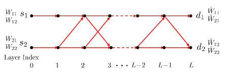
In this section we consider a special class of layered networks – the network. By network, we mean a layered multihop network with layers ( hops), and with only two nodes at each layer. Such an example is shown in Fig. 2.
Since the DoF min-cut 1 case is trivial, let us consider DoF min-cut 2 networks. Between two adjacent layers, we enumerate all topologies of a one-hop component in Fig. 3.
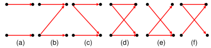
There are six cases (a) to (f) depending on the connectivity. Case (a) is trivial because two layers can be collapsed into one. Since the sum capacity of networks is not affected by switching node labels within a layer, it is clear that subnetworks (e) and (b) are equivalent, and similarly subnetwork (f) is equivalent to (c). Therefore, in the following we only consider the permutations of three components (b), (c), (d). For brevity, we call the three components (b), (c), (d) the “Z”, “S” and “X” components, respectively.
We have the following DoF result.
Theorem 1: For networks defined above, the DoF are given by:
-
(A)
DoF , if , and the network is a “Z” or “S” network.
-
(B)
DoF , if , and the network is an “X” network.
-
(C)
DoF , if , and the network is one of the eight networks: XZL-1, XSL-1, ZL-1X, SL-1X, ZSL-1, SZL-1, SL-1Z and ZL-1S.
-
(D)
DoF , otherwise.
Proof: Cases (A) and (B) follow from previously known results [4].
Case (C): Since switching node labels within each layer does not affect sum-capacity for the setting, the eight connectivity patterns for Case (C) can be reduced to the four patterns : XZL-1, ZL-1X, ZSL-1 and SL-1Z. Further, due to the space limitation, we only sketch the argument that shows that the DoF of XZL-1 network is . Detailed proofs for all connectivity patterns are presented in the full paper [7].
The layered XZL-1 network is shown in Fig. 4. Let us first consider the DoF outer bound.
DoF Outer Bound: Because each of the source and destination nodes has only one antenna, it is trivial to see that the following four inequalities are satisfied:
| (2) | |||||
| (3) | |||||
| (4) | |||||
| (5) |
In Fig. 4, the destination node can decode its desired messages and . Since the path from to , i.e., , is free of interference, and the two messages must go through this path, every relay node in this path can decode as well.
Consider the node . Let us set the message to bound the rates for the remaining three messages. Since is able to decode the message , after decoding it can remove the signal carrying originating from , and then obtain an AWGN channel directly connected to the source . Therefore, subject to the noise distortion which does not affect the number of DoF111We use the phrase ”subject to noise distortion” to indicate the widely used (see e.g., [4]) DoF outer bound argument whereby reducing noise at a node by an amount that is SNR independent (and therefore inconsequential for DoF) allows it to decode a message., can also decode the messages and . Since single-antenna node is able to decode all the three messages and , we have the following DoF outer bound:
| (6) |
Similarly we can set . Again since is able to decode whatever can decode, can decode first and then remove the signal carrying it and thus only sees an AWGN channel directly connected to . Subject to the noise distortion can also decode the messages and , and thus we have another inequality:
| (7) |
Adding up all inequalities (4), (6) and (7), we have:
| (8) |
Therefore, we have the outer bound DoF .
Achievability: We are going to show a simple scheme that can achieve DoF. We claim that the XZL-1 () network can also achieve DoF if the two-hop XZ network achieves DoF. Intuitively, this is because by simply repeating (amplify and forward) whatever the intermediate relays from the to layers receive, we can convert “ZL-1” to one “Z” component. Thus, we only need to prove DoF is achievable for the two-hop XZ network, as shown in Fig.5.
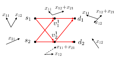
The achievable scheme relies on the idea of aligned interference neutralization. In addition, since the channel is constant, we will use signalling in rational dimensions first introduced in [8, 9]. Over two rational dimensions222The concepts of rational dimensions and rational independence, first proposed for real-valued numbers, can be applied to complex-valued numbers as well, as reported in [10]. Also, if the channel is time-varying or frequency-selective, we can also create linear space by using symbol extension, and the rational alignment scheme can be translated to the linear scheme., sends two symbols , and sends each carrying DoF and along a “beamforming” direction. As shown in Fig. 5 we first randomly pick the direction of at . Note that although we use vectors to denote the “beamforming” directions in Fig. 5 for simplicity, they should be rationally independent numbers. The direction of at is then fixed by aligning two symbols and at , and the direction of at is fixed by aligning two symbols and at . At the first layer, sends two symbols and , each carried by a randomly picked beamforming direction. The node first demodulates and , and then only sends with a beamforming direction such that can be canceled at by the signal coming from . Since the directions carrying and are rationally independent, the destination is able to decode them, thus achieving one DoF. Also, because only sends , and the destination sees a clean channel, can decode its desired symbol as well to achieve DoF. Therefore, a total of DoF is achievable.
Case (D): In this case, we claim that except for the connectivity patterns covered in case (C), all the other channels where have DoF. The DoF outer bound for these networks is trivial and the achievability can be shown based on eliminating two of the 4 messages to reduce the network to an interference channel, so that the results of [2] can be applied. The main observation here, as also in [2], is that in layered multihop networks if interference arrives through more than one path, it can be neutralized.
The eight cases in class (C) have two characteristics: (1) there is only one path from to or from to , and (2) the “Z” or “S” components should be consecutive.
If the first condition does not hold, then it implies that from to and from to , the number of paths is zero or more than one. In this case, by setting , either there is no interference, or there are more than 1 paths carrying interference which allows interference neutralization. In either case, 2 DoF are achieved.
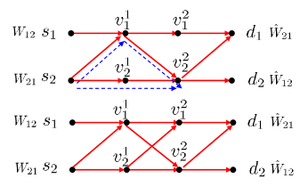
Next, consider the class of connectivity patterns where the second condition is not satisfied but the first condition still holds. In Fig. 6 we show two specific networks characterizing the main properties of this class of networks. Take the first as an example, if we set then it forms a two user interference network, in which it is easy to see that two DoF are achievable even though there is only one path from to . This is because the message intended for the destination can always be nulled at after going through two paths and (denoted by the dashed lines) such that and thus is interference-free. Since can still arrive at through the path , the destination can achieve one DoF. Similarly, can also ahieve one DoF. Thus, a total of two DoF is achievable. \QED
4 DoF of General Multihop Layered Network
So far, we studied the DoF of networks where there are only two relay nodes at each layer. If the number of relay nodes is not limited to two, one question is whether the DoF of the network with arbitrary connectivity still belong to the set . Interestingly, there is another class of networks that have DoF. Due to the space limitation, we will only show one specific example in such a new class. The detailed description and analysis for this new class are reported in [7].
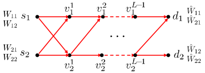
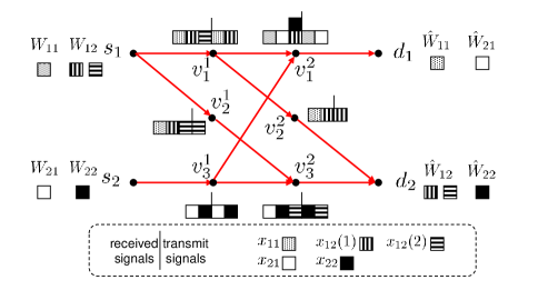
Theorem 2: The network of Fig. 7 has DoF.
4.1 DoF Outer Bound
Similar to the analysis in Case (C) of Section III, if we set , then we have the following inequality:
| (9) |
Notice that only depends on . Because is able to decode , can decode it as well. After decoding , can subtract the signal carrying , thus obtaining subject to the noise distortion which depends on the channel coefficients but is independent of SNR, and thus has only an impact on the rate. Since can decode and , can decode as well. Thus, the single-antenna node can decode all these three messages, which implies (9).
Next we derive a new information-theoretical DoF outer bound. Consider the sum rate of two messages desired at the destination . A genie provides to the node .
| (10) | |||||
| (11) | |||||
| (12) | |||||
| (13) | |||||
| (14) | |||||
| (15) | |||||
| (16) | |||||
| (17) |
Here, (10) follows from Fano’s inequality. (11) follows from the data processing inequality, because forms a Markov chain. (12) is obtained because providing genie does not decrease the capacity region of the network. (13) follows from the chain rule. (14) is obtained since is independent of . (17) follows from the invertibility of the channels (regardless of the values of the channel coefficients as long as they are all non-zero), which implies that given the entropy of is equal to that of subject to the noise distortion. Specifically, knowing we can reconstruct the signal , and by subtracting it from we obtain the signal subject to the noise distortion which will depends on the channel coefficients but is independent of SNR. The entropy of is equal to that of subject to the noise distortion which again depends only on the channel coefficients but is independent of SNR. All these operations only have an impact on rate, and so we obtain as shown in (17). By rearranging terms of (17) we obtain the first outer bound:
| (18) |
Next, let us consider the sum rate of two messages originating from the source . A genie provides to the nodes and .
| (19) | |||||
| (20) | |||||
| (22) | |||||
| (24) | |||||
| (27) | |||||
where (19) follows from Fano’s inequality. (20) follows from the data processing inequality because , and form two Markov chains. (24) follows from the invertibility of channels which implies that using we can recover the signal subject to the noise distortion. Specifically, we can use to decode because only depends on . Thus, using and we can recover the signal subject to the noise distortion. By knowing we also know . Thus, given , we can reconstruct the signal subject to the noise distortion. Finally, given we can reconstruct the signal . All these operations only have an impact on rate, so we obtain as in (24). (27) is obtained since are independent of . (27) follows from the chain rule. By rearranging terms of (27) we obtain the second outer bound:
| (28) |
4.2 Achievability of DoF
We provide an interference alignment scheme that can achieve DoF in the network in Fig.7. Over three rational dimensions, source sends one symbol to , two symbols to , and sends one symbol to , and one symbol to , each carrying DoF along a rationally independent “beamforming” direction. For brevity, in Fig. 7 we also use boxes (each box denotes one symbol, carrying DoF) with different patterns, to show how our scheme works. We consider the transmission schemes from each layer to the next in what follows.
From layer 0 to layer 1: The source randomly picks three rationally independent beamforming directions to transmit . Because the edges and are AWGN channels, and both can decode these three symbols. Similarly, can decode .
From layer 1 to layer 2: After decoding , and , sends and to and using any two rationally independent beamforming directions and , respectively. only sends to with a randomly picked beamforming direction. sends with another randomly picked beamforming direction, but in the direction such that aligns with at in the same dimension, i.e., .
From layer 2 to layer 3: The node can see a three-rational dimensional space, each dimension carrying symbols , and , respectively. Thus, it can demodulate these symbols and only transmits , to the destination such that achieves DoF. receives two symbols and in two dimensions, and thus it can demodulate them and only sends to the destination with an randomly picked beamforming direction. Similarly, receives three symbols in three rationally independent dimensions. Thus, it can demodulate them and only transmits to with two randomly picked rationally independent beamforming directions. At the destination , because it receives three desired symbols in three rationally independent dimensions, it can achieve 1 DoF.
Therefore, a total of DoF is achievable almost surely.
Since both outer and inner bounds are DoF, we establish that the network has a total of DoF. \QED
5 Conclusion
Total degrees of freedom (DoF) for multiple unicasts over 2 source 2 sink layered multihop wireless networks are shown to take values , depending on the connectivity within each hop, for almost all values of channel coefficients, when the number of relayed in each layer is no more than 2. If the number of relays at each layer is not restricted to 2, it is shown through an example, that the network can also have DoF value . Finally, we are able to show in [7] that 1, 4/3, 3/2, 5/3 and 2 (in the almost surely sense) are the only possible DoF values for all connectivity patterns.
Acknowledgement
The authors would like to acknowledge prior collaboration with Hamed Maleki at UC Irvine and Prof. Sriram Vishwanath at UT Austin for the wired network capacity result.
References
- [1] T. Gou, S. Jafar, S. Jeon, S. Chung, “Aligned Interference Neutralization and the Degrees of Freedom of the Interference Channel”, e-print arXiv:1012.2350, Dec. 2010.
- [2] I. Shomorony and S. Avestimehr, “Two unicast wireless networks: characterizing the degrees-of-freedom”, arXiv:1102.2498, Mar. 2011.
- [3] K. Cai, K. B. Letaief, P. Fan, R. Feng, “On the Solvability of 2-pair Unicast Networks — A Cut-based Characterization”, arXiv:1007.0465v1, July 2010.
- [4] S. Jafar, S. Shamai, “Degrees of Freedom Region for the MIMO Channel”, IEEE Transactions on Information Theory, vol. 54, No. 1, pp. 151-170, Jan. 2008.
- [5] V. Cadambe and S. Jafar, “Interference alignment and the degrees of freedom of wireless networks”, IEEE Trans. on Information Theory, vol. 55, no. 9, pp. 3893–3908, Sep. 2009.
- [6] M.A. Maddah-Ali, A.S. Motahari , and A.K. Khandani, ”Communication Over MIMO Channels: Interference Alignment, Decomposition, and Performance Analysis,” IEEE Transaction on Information Theory, Vol. 54, No. 8, pp. 3457-3470, Aug. 2008.
- [7] C. Wang, T. Gou and S. Jafar, “Degrees of Freedom of Layered Multihop Networks”, Full paper in preparation.
- [8] R. Etkin and E. Ordentlich, “The Degrees of Freedom of the K User Gaussian Interference Channel Is Discontinuous at Rational Channel Coefficients”, IEEE Trans. on Infor. Theory, vol. 55, no. 11, Nov. 2009.
- [9] A.S. Motahari, S. O. Gharan and A. K. Khandani, “Real Interference Alignment with Real Numbers,” arXiv:0908.1208, Aug. 2009.
- [10] M.A. Maddah-Ali, “On the Degrees of Freedom of the Compound MIMO Broadcast Channels with Finite States”, arXiv:0909.5006v3, Oct. 2009.