Pushing the limits of Full-duplex: Design and Real-time Implementation
Abstract
Recent work has shown the feasibility of single-channel full-duplex wireless physical layer, allowing nodes to send and receive in the same frequency band at the same time. In this report, we first design and implement a real-time 64-subcarrier 10 MHz full-duplex OFDM physical layer, FD-PHY. The proposed FD-PHY not only allows synchronous full-duplex transmissions but also selective asynchronous full-duplex modes. Further, we show that in over-the-air experiments using optimal antenna placement on actual devices, the self-interference can be suppressed upto 80dB, which is 10dB more than prior reported results. Then we propose a full-duplex MAC protocol, FD-MAC, which builds on IEEE 802.11 with three new mechanisms – shared random backoff, header snooping and virtual backoffs. The new mechanisms allow FD-MAC to discover and exploit full-duplex opportunities in a distributed manner. Our over-the-air tests show over 70% throughput gains from using full-duplex over half-duplex in realistically used cases.
1 Introduction
Half-duplex communication, where a node can either transmit or receive in a single channel, is the commonly imposed constraint in the design of all practical wireless networks. In the last two decades, many works [1, 2, 3, 4, 5, 6, 7, 8] have reported experiments and/or models for full-duplex communications. Perhaps the most encouraging results were reported by two groups simultaneously [7, 8] which used off-the-shelf hardware to demonstrate that single-channel full-duplex wireless can in fact be implemented and provides measurable gains over half-duplex systems. However, most work till date has limited its attention to two nodes exchanging information with each other, with the focus on physical layer feasibility – a crucial first step. However, there is no prior work on the design of medium access protocols which leverage full-duplex communications in multi-node networks.
In this report, we propose the first full-duplex random access protocol, FD-MAC. Further, we implement a real-time OFDM-based full-duplex physical layer (FD-PHY for short) and the proposed FD-MAC on a WARP-based testbed. Our major contributions for FD-PHY and FD-MAC are as follows.
FD-PHY: We develop and implement a real-time full-duplex capable physical layer, FD-PHY. The OFDM-based FD-PHY has 64 sub-carriers and occupies 10 MHz bandwidth. The key challenge in full-duplex communications is the large self-interference caused by a node’s own transmissions, which can completely swamp the packets from other nodes. Thus, analog cancellation (passive and/or active) is essential to reduce the power of self-interference compared to the packet of interest before the analog-to-digital converter converts the signal from the antenna. We implement an active analog cancellation which injects an appropriately scaled canceling signal at the receive antenna, to reduce the self-interference. This active cancellation is implemented on a per subcarrier basis, and can thus be applied to any OFDM PHY with arbitrary number of subcarriers.
In [7, 8], the self-interference cancellation was performed both in analog and in digital baseband, together providing nearly 70 dB of attenuation to self-interference signal. We explore another avenue of attenuating the self-interference – the role of physical placement and orientation of transmit and receive antennas on actual mobile devices, like laptops and tablets. We conduct extensive experiments by mounting the antennas on an iPad-sized device for different antenna configurations. The main finding is that device-induced attenuations combined with analog cancellation can lead to 80 dB of self-interference suppression, even without baseband cancellation. This finding further strengthens the case for actual deployment of full-duplex communication in mobile devices.
Further, the proposed FD-PHY is also capable of enabling asynchronous full-duplex communications in some cases, which further expands the design space for medium access protocols. We show that a full-duplex capable node can begin to receive a packet from a node while transmitting to another node, albeit with a 3 dB loss for the same bit error rate (BER). However, the other case where a full-duplex-capable node wants to transmit a packet while receiving a packet is not possible to implement reliably. This imposes important constraints on medium access protocols, which the proposed FD-MAC completely adheres to.
FD-MAC: Leveraging the capabilities of FD-PHY, we develop and implement a random access protocol FD-MAC for infrastructure-based WiFi-like networks, where all flows are between an access point and mobile units. We use IEEE 802.11 packet structure with an additional FD header. The key challenge in maximally using full-duplex capability is to discover the opportunities to send and receive at the same time in a completely distributed manner. Since nodes only have the knowledge about the packets in their own queues, discovering a full-duplex opportunity requires sharing queue information with neighboring nodes. At the same time, any MAC protocol has to allow opportunities for all nodes to access the medium while trying to maximize network throughput. The FD-MAC uses three mechanisms to achieve this balance.
First mechanism is the shared random backoff, which temporarily couples the backoff counter for two nodes which have discovered that they have a packet for each other. The discovery that two nodes have a packet for each other is performed via the FD headers in every DATA and ACK packets. If the two nodes have many packets for each other, the FD header allows nodes to keep discovering these full-duplex opportunities. One possibility is that the nodes can occupy the medium and continuously transmit to each other. However, while this maximizes the use of full-duplex mode, it can potentially starve other nodes. Thus, we propose that once two nodes discover that they have more packets for each other, they use the 10-bit SRB (shared random backoff) field in FD header to share a backoff counter with each other. The two nodes backoff for a common duration to stay synchronized and at the same time allow other nodes to contend and capture the channel. Thus the protocol balances access with the maximal use of full-duplex mode.
The second mechanism involves nodes snooping on headers of all ongoing transmissions within radio range, even when the nodes have frozen their counters during network allocation vectors (NAV). The packet snooping allows nodes to estimate their local topology and in turn discover if the ongoing transmissions between the access point and other nodes forms a clique or hidden node with themselves. If a Mobile estimates that it will form a clique with the ongoing AP to Mobile flow, then cannot exploit full-duplex since its new transmission will collide with ongoing flow, either at AP or at Mobile . However, if – AP – forms a hidden node topology, then the asynchronous full-duplex capabilities of FD-PHY enable injecting a new packet to AP while AP is sending a packet to .
Lastly, FD-MAC uses two virtual contention resolution mechanisms which further balance the objective to maximally exploit full-duplex mode to allowing access to other competing flows. The salient mechanism is the case where the AP looks at multiple packets in its buffer (not just head of line packet) and statistically decides which packet it will serve first. By looking into multiple packets in the queue, AP can discover more opportunities to use the full-duplex mode. This, of course, leads to the possibility of AP delaying the transmission of its HOL packet which could be problematic at higher layer protocols. So we propose to send a non-HOL packet with vanishing probability. Of course, this mechanism is optional and can be completely turned off at the cost of reduced use of full-duplex capabilities. Our experimental results show that FD-MAC achieves a throughput gain of up to 70 over comparable half-duplex systems. The gain is a function of distance, packet arrival pattern, extent of contention etc.
The rest of the report is organized as follows. In Section 2, we review the challenges and state-of-the-art in full-duplex wireless communications. In Section 3, we describe the OFDM-based full-duplex physical layer (FD-PHY) study antenna placement on actual devices and the performance of asynchronous full-duplex. In Section 4, we describe the mechanisms for FD-MAC and study its behavior in prototypical topologies, finally presenting its evaluated performance.
2 Review of Full-duplex Wireless
2.1 Main Bottleneck in Enabling Full-duplex
To appreciate the key challenge in achieving full-duplex wireless, consider the two-way link shown in Figure 1, where the two nodes are trying to send and receive a packet simultaneously in the same frequency band. Node 1 has a packet for Node 2 and vice versa. Since the situation is symmetric, we can focus our attention on Node 1. Assuming that the transmit and receive antenna are physically different, the power of signal transmitted by the node by Antenna T1 causes self-interference at the receiving antenna of the node, Antenna R1, which can be anywhere from 15–100dB higher than the signal of interest coming from transmit antenna Antenna T2 of Node 2. Since most modern systems process the received signal digitally to decode packets, the analog received signal is converted to the digital form using an analog-to-digital converter (ADC). With such large difference in the powers from the two signals, self-interference and signal of interest, the finite resolution of the ADC is the main bottleneck in enabling full-duplex communications.
When two radio signals impinge on the antenna, the voltage generated at the antenna is the sum of the two signals. That voltage is down-converted to the baseband frequency and scaled such that the sum of the two signals occupies a voltage range (nominally denoted as [-1,1]) such that full dynamic range of the ADC is used. This ensures the best possible representation of the analog signal in the digital domain. If one of the signals is much smaller than the other signal, then it effectively gets fewer bits to represent its voltage levels compared to the case where the smaller signal arrived at the ADC by itself. That is because in the latter case, the automatic gain control algorithm will scale the signal to occupy the whole ADC range and thus allow more bits of resolution for the smaller signal by itself.
Thus, even if the SNR of the signals was individually high, the wide discrepancy in their relative amplitudes implies that the smaller signal will have lower effective SNR in the digital domain, leading to the stronger signal swamping the weaker signal. Thus signal-to-interference-plus-noise ratio (SINR) is an important metric to determine the performance of any method for full-duplex communications.
2.2 Reported Methods
To achieve full-duplex communication over reasonable distances, it is thus important to suppress the self-interference in the analog domain before it reaches the ADC. In 2010, two groups [7, 8] reported two different techniques to achieve approximately 60-70dB of self-interference suppression, thereby showing the feasibility of full-duplex transmissions. In [7], the authors proposed an antenna cancellation method using two transmit antennas to use beamforming to create a null at the receive antenna. Three physical antennas are needed in the proposed method to achieve SISO full-duplex. The prototype demonstration showed full-duplex performance for short inter-node distances like those encountered in IEEE 802.15.4 (e.g ZigBee) equipped devices. Perhaps a key deployment challenge is the need for large antenna separation to achieve antenna cancellation, especially for IEEE 802.15.4 devices which are often targeted for small form-factor devices and thus may not have the required physical space to accommodate the antennas.
In [8], the authors repurposed MIMO RF chains to generate a canceling signal and add it in analog at the antenna using RF adder. While this technique does not have the drawback of the additional antennas like in [7], the prototype implementation in [8] had a very narrow bandwidth (0.625 MHz) and thus its applicability to wide-band systems like 802.11 was not established.
3 Real-time Full-duplex PHY
In this section, we first describe our wideband, OFDM-based, full-duplex physical layer implemented on an off-the-shelf SDR platform and methods to optimize antenna placement on actual electronic devices to improve the capacity and range of full-duplex wireless physical layer. Based on this implementation, we compare the performance of full-duplex wireless with half-duplex physical layers. Finally, we discuss the challenge in enabling asynchronous full-duplex systems, and how our proposed design achieves partial asynchronous full-duplex transmissions.
3.1 Real-time OFDM Transceiver
The conceptual block diagram of our full-duplex physical layer is shown in Figure 2. We use the narrowband technique proposed in [8] for reducing self-interference in the analog domain, and apply it to a wideband OFDM (orthogonal frequency division multiplexing) system by processing each subcarier independently.
Consider Node 1 in Figure 1. Denote the channel between transmit antenna T1 and receive antenna R1 for sub-carrier as , where with being the total number of sub-carriers in the OFDM system. Further, let the signal sent in sub-carrier be denoted as . Then the self-interference seen at the receive antenna in the subcarrier, without any cancellation, is given by
| (1) |
The above representation assumes that cyclic prefix is longer than the time delay of the multipath. This assumption is easily satisfied for the self-interference channel since the distance between the transmit and receive antennas of the self-interference channel is very small, thereby resulting in very limited multipath delay. In most systems, the cyclic prefix is designed for long distances between two nodes, like N1 and N2 in Figure 1.
Following [8], we opt for active self-interference cancellation by using the physical layer architecture shown in Figure 2, where we compute the canceling signal and cancel it before the received signal from the receive antenna R1 reaches the analog to digital converter. This cancellation is not performed over the air [7] but using a wired assembly and thus does not need extra antennas. Let the wireline channel between the cancellation transmit chain and receive antenna R1 be represented as for sub-carrier ; note that wires are also a channels and thus can attenuate and change phases like wireless channels.
The cancellation signal for the subcarrier is computed as
| (2) |
where and represent the estimates of channels and . In general, the estimates have errors and thus not equal to the quantity they are estimating. So, the self-interference signal received at the receive antenna after active analog cancellation is
| (3) |
From (3), it is clear that if the channel estimates were perfect, the self-interference can be completely suppressed in this technique. This is equivalent to perfect nulling in the ideal case for the antenna cancellation technique proposed in [7].
Since we need to estimate two sets of channels and , we can view the system as a two-transmit chain system (like in IEEE 802.11n MIMO modes) and can exploit the already available physical layer headers in MIMO packets. Thus, no special PHY headers need to be added to estimate the required channels to compute the canceling signal.
We leveraged the open-source MIMO physical layer designs available at the WARP website [9] as the starting point for our implementation. The open-source design occupies 10 MHz bandwidth using 64 sub-carriers and also supports 22 MIMO transmissions. One of the modes in the open-source design is spatial multiplexing, where the transmitter sends two different streams of the data to two transmit antennas. We repurposed the spatial multiplexing mode to implement the above scheme, where the second stream in the MIMO design is replaced by the canceling signal , which requires multiplying the first signal by appropriate canceling coefficients . The other major component in our design is the design of estimation procedure to obtain the required channel estimates and . Here again, we used the MIMO channel estimation blocks in the open-source design [9] and hence the details are not provided in this report due to lack of space. the
3.2 Antenna Placement on a Mobile Devices
We next investigate how full-duplex will perform on actual mobile devices.
The form factor of the mobile device limits its antenna placement, distance between transmit and receive antennas, and orientation of the antennas. At present none of the small form factor mobile devices, like smartphones, use 802.11n MIMO modes since they cannot accommodate two RF chains on one device. Thus, we limit our attention to larger form factor devices, like tablets and laptops.
The driving questions are how should we place the transmit and receive antennas on a mobile device to optimize the performance of full-duplex nodes. We consider three configurations as shown in Figure 3, with each configuration including two antennas – one for transmit and one for receive.
Configuration A: While most omni-directional antennas used in commercial devices (laptops and tablets) are reasonably omni-directional in the far field, they are almost never truly omni-directional in the near field. Most omnidirectional antennas have small energy transmission along the z-axis (i.e, above and below the antenna) [10]. The antenna pattern immediately suggests a potential deployment scenario, where the transmit and receive can be mounted on top of each other; this is labeled as Configuration A in Figure 3.
Configuration B: In many 802.11n equipped devices which have two antennas to support MIMO modes, the antennas are often installed on the opposite end of the device (like the opposite edges of the screen) to create sufficient separation between the antennas. This is labeled Configuration B in Figure 3. The maximal separation between the antennas creates statistically nearly-independent channels to achieve MIMO spatial multiplexing gains. While Configuration B was not designed for full-duplex operation, the presence of the actual device (e.g laptop) between the antennas has the potential to create additional path loss between the two antennas and thereby increase the attenuation of the self-interference.
Configuration C: Finally, we will also test the case when one of the antennas is installed perpendicular to the other antenna, labeled Configuration C in Figure 3. This configuration aims to exploit the potential difference in radiation pattern along different axes.
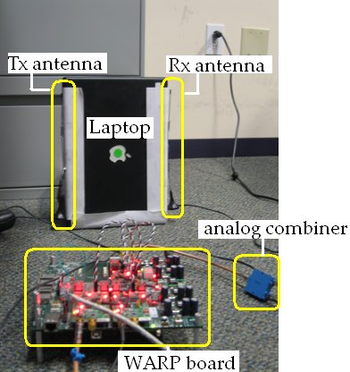
The experiments are performed by strapping the two 2.4 GHz 7 dBi Desktop Omni Antenna (typical Wifi Antenna) to a iPad-sized device in different configurations. The dimensions are shown in Figure 3. We fix the transmit power at 6 dBm. For each configuration, we test the impact of antenna configuration and the device. The results are summarized in Table 1. The full-duplex PHY was implemented on WARP boards, each with three radio cards. One radio was connected to the transmit antenna, the second was connected to the receive antenna and the third provided the canceling signal () over a wire and added in analog after the receive antenna.
| Config. | Device | Interference | Interference | Total |
| Present | power | after analog | sup- | |
| cancellation | -pression | |||
| A | No | -28dBm | -52dBm | 58dB |
| A | Yes | -28dBm | -52dBm | 58dB |
| B | No | -46dBm | -71dBm | 77dB |
| B | Yes | -51dBm | -75dBm | 81dB |
| C | No | -40dBm | -63dBm | 69dB |
| C | Yes | -49dBm | -73dBm | 79dB |
Four main results stand out from the Table 1.
Result 1 (Device reduces self-interference): Depending on the configuration, the presence of a device (e.g laptop/iPad) can make a significant impact on the power of self-interference, by passively attenuating the signal. The metallic components in a laptop-like device can significantly attenuate the signal and thus reduce self-interference. In Configuration C, device results in an additional attenuation of 9dB attentuation compared to the case when the device is not present. The device related attenuation is 5 dB in Configuration B and 0 dB in Configuration A.
Result 2 (Best full-duplex configuration): The best configuration in terms of self-interference power, with and without analog cancellation is Configuration B, where the self-interference power with and without the analog cancellation is lowest compared to other configurations. This is, in fact, great news because Configuration B is also the ideal configuration for MIMO systems. Thus, there is a potential to use multiple antennas in either MIMO or full-duplex modes in mobile devices.
Result 3 (Baseband cancelation): In [7, 8], baseband cancellation was also proposed to reduce the self-interference power. In our design, we did not implement base-band cancellation due to lack of sufficient FPGA logic on our WARP boards, but we can still achieve a self-interference suppression which is more than the prior work due to added suppression by the device.
Result 4 (RF requirements for canceling signal path): The self-interference power before analog cancellation in all configurations is more than 30dB. For example, in Configuration A, the received power with device is -28dBm for transmit power of 6dBm, which implies 34dB loss in signal power when the self-interference reaches receive antenna. This implies that the canceling transmit RF chain does not require a power amplifier, because the canceling signal travels over a wire and thus suffers only minor attenuation. In fact, we had to install 40 dB attenuators on our off-the-shelf radio cards, which essentially removed all the power amplification by the power amplifiers. This is again an encouraging news, which shows that the full-duplex transceiver needs one full transmit chain (up-converter for transmit antenna), one radio chain (down-converter for receive antenna) and a partial transmit chain without power amplifier (for canceling signal). Thus, compared to SISO transceiver (one transmit and one receive RF chain), full-duplex only needs the additional partial transmit chain.
3.3 Asynchronous Full-duplex
So far, the PHY analysis in prior works [7, 8] and in Section 3.2 has been motivated by two nodes exchanging packets with each other as shown in Figure 1. However, full-duplex can be employed in more general cases. Consider the hidden node topology in Figure 4(b), where is out of radio range of . Assume AP has a packet for and has a packet for AP. In this case, since the AP has to be a full-duplex node, the key question is if the full-duplex mode can be enabled in an asynchronous manner. That is, can a new flow be added once a flow starts transmission. In the hidden node example, there are two possibilities for AP: (a) start receiving a packet from after having initiated a transmission to , (b) start a transmission to while receiving a packet from .
A new reception while transmitting: Assume that AP is actively transmitting to and is continuously operating its analog canceler to suppress its own self interference. This ensures that when starts a packet, it can be decoded by AP’s receiver. The key challenge is that AP has to estimate the channel between and AP in the presence of self-interference, which is required to be able to decode ’s packet at AP. In almost all current systems, even with multiple users, this training is performed without any (intentional) interference.
However, to enable asynchronous full-duplex, we are required to estimate the channel between and AP in the presence of self-interference caused by AP’s ongoing transmission. We label the physical layer channel estimation in the presence of ongoing transmission as dirty estimation, and quantify the loss compared to the conventional systems, all of which have clean estimation.
| SINR | BER | BER |
|---|---|---|
| dirty | clean | |
| (with canceler) | estimation | estimation |
| 18 dB | ||
| 14 dB | ||
| 11 dB | ||
| 8 dB | ||
| 7 dB |
In Table 2, we report the results for
different values of SINR which were achieved by changing the distance
between the two nodes and AP. From
Table 2, it is clear that estimating the
AP channel in the presence of self-interference
increases the bit error rate (BER) for all distances. The impact is
worse as the SINR reduces; for high SINR, there is hardly any
measurable loss and for low SINR, the BER in dirty estimation system
can be 6 times compared to clean estimation, which turns out to be up to 3 dB loss in effective SINR for the asynchronous packet. This implies that
the capacity of the full-duplex transmission is reduced if
full-duplex is used in this asynchronous mode.
A new transmission while receiving: Now we consider the converse case, where AP is already receiving a packet from M2 and intends to send a packet to M1 to leverage its full-duplex capabilities. Unfortunately, this mode cannot be enabled reliably.
The key challenge is calculation of the self-canceling signal in the presence of an ongoing reception. To compute the canceling signal , we need to estimate the channel coefficients and . If the MIMO PHY header is transmitted (as described in Section 3.1) while PHY is receiving a packet, then the large uncanceled self-interference will completely swamp the ongoing reception. This is because self-interference before cancelation is almost always much bigger than signal of interest (as also discussed in Section 2). While receiving the packet, the automatic gain control (AGC) is set to ensure that the incoming signal occupies the full dynamic range of the analog-to-digital converter (ADC). Thus the process of estimating the channels to establish canceling signal causes a “self-collision” at the receiver.
A possible approach is to backoff on how much of the dynamic range is occupied by the receiving packet, thus allowing a big uncanceled signal to not completely destroy the packet. The drawback of lost bits of resolution is that the quantization noise of the receiver is increased, which decreases its effective SINR, increasing BER and thereby reducing overall throughput.
Another approach will be not estimate the self-interference channel and simply use older estimates for the desired channels. In our experiments, the self-interference channel with a device in the middle had sufficient variations over time, which implies that self-interference canceler can end up doing more harm than good if it has outdated channel estimates. This again, leads to the same situation where full-duplex cannot be enabled reliably.
Result 5 (Allowable asynchronous modes): The key result is that asynchronous full-duplex can be enabled to receive while transmitting (with some loss in the performance of receiving packet) but not transmit while receiving.
4 MAC protocol design
In this section, we will describe Full-Duplex Medium Access Protocol (FD-MAC) which uses the full-duplex-capable physical layer described in Section 3. We will limit our attention to infrastructure based systems and focus on the scenario involving one access point (AP). This will allow us to define the fundamental elements of a full-duplex MAC protocol.
4.1 Challenges in MAC Design
The first challenge in designing full-duplex MAC is identification of the nodes which can engage in a full-duplex mode. In any network of multiple nodes, multiple flows with random arrivals exist at the same time, leading to random instances when full-duplex can be used.
The second challenge is imposed by the physical layer. From Section 3.3, either full-duplex has to be performed synchronously between two nodes (a packet exchange) or can be done asynchronously only if a full-duplex node receives a packet while transmitting a packet to another node. Any MAC design has to respect this constraint in its design.
The third challenge is shared by any MAC protocol (full or half-duplex) and is to provide opportunity to all nodes to access the medium. Thus, the access protocol should not unduely favor full-duplex opportunities over half-duplex flows.
4.2 Overview of FD-MAC
In the infrastructure-based network, all flows have either AP as their source or destination. Thus, at any given time, a maximum of two flows can be active among full-duplex capable nodes. The two possible scenarios which leverage full-duplex capabilities are shown in Figure 4(a) and 4(b), where (i) AP and mobile node are exchanging packets or (ii) AP is sending and receiving a packet simultaneously from two mobile nodes and , which are hidden from each other.
FD-MAC is a random access protocol, which will use most of the dominant elements of the IEEE 802.11 DCF. However, while IEEE 802.11 is CSMA/CA, collision avoidance in FD-MAC is done selectively to leverage full-duplex opportunities. FD-MAC introduces following three new protocol elements.
Shared random backoff: When two nodes, say AP and in Figure 4(a), are in a situation where they have many packets for each other and thus truly exploit full-duplex, they do not continuously capture the medium in order to allow other nodes to send or receive from AP. Instead they agree on a shared random back-off which allows other nodes to contend for the medium. If no one else wins, the two nodes can continue with their full-duplex transmission.
Snooping to discover full-duplex opportunities: In FD-MAC, nodes decode headers of all ongoing transmissions, even when network allocation vector NAV is non-zero. This allows the nodes to estimate the local topology and initiate full-duplex opportunistically.
Virtual contention resolution: FD-MAC also has two virtual contention mechanisms to balance use of the full-duplex mode with access for all nodes in the network.
While the FD-MAC can be used with or without RTS/CTS, we will only describe for the more popular use case of infrastructure mode of 802.11 which does not use RTS/CTS.
4.3 FD-MAC Packet structure
We adopt IEEE 802.11 packet structure and add a new FD header, for managing full-duplex transmissions as shown in Figure 5. Each packet contains a PHY header, a MAC header, a full-duplex header, a payload and a cyclic redundancy check (CRC). Except for the full-duplex (FD) header, all other fields are identical to IEEE 802.11 packets. We briefly explain the fields which are essential to describe FD-MAC.
The PHY header has a preamble and the training symbols necessary for the functioning of the physical layer. The existing elements of the MAC header that we use in our FD-MAC protocol are Duration ID denoting the duration (DUR) of the packet, source address (SA), destination address (DA) and FRAG (denoting if there are more fragments of the same packet in line for the destination). The MAC header distinguishes between data packet and acknowledgement. For simplicity of description of the FD-MAC protocol, data packets will be referred as DATA and acknowledgement as ACK.
The FD header has a one-bit field to distinguish packet type (DUPMODE) which can either assume values HD (indicating that it is a half-duplex packet) or FD (indicating that it is a full-duplex packet). Then there is a one-bit field, Head-of-line (HOL), indicating that the next packet in the buffer is for the destination of the current packet. The current 802.11 MAC header has a field labeled ‘more data’ in Frame Control Field of MAC header, but to avoid any conflict with other uses this field, we have defined HOL in the FD header. The overall overhead increase is minimal since the HOL is only 1-bit long.
The next field reveals the duration of head of line packet, DURNXT, and is useful when HOL = 1. It 2 bytes long. The next field is meant for revealing duration of the full-duplex exchange, DURFD. It too is 2 bytes long.
The next one-bit is a Clear-To-Send (CTS) indicating that destination of the current packet can send a packet to source of the current packet. Finally the FD header has a field for a 10-bit number which is the Shared Random Backoff (SRB).
Fields DURNXT and DURFD are needed in order to counter the hidden node problem in infrastructure mode of 802.11. They are optional and in their absence, the FD header is only 13 bits.
4.4 Shared Random Backoff
Consider the most basic two-node example shown in Figure 4(a). It is possible that at any given time either both nodes have a packet for each other or only one node has a packet for the other. Note that in this case, asynchronous full-duplex is not possible because of the PHY constraints (Section 3.3), where a node cannot start a new transmission while it is receiving a packet. Thus, nodes have to find a way to synchronizing their transmissions, such that they can estimate the channel coefficients for maximal self-interference cancellation (as discussed in Section 3.1).
To maximize the use of full-duplex mode while respecting the constraints imposed by the physical layer, FD-MAC proceeds as follows. Assume that the nodes contend for the medium since they do not know if both nodes have a packet for each other or not. Without loss of generality, assume that AP wins the contention resolution. Then if the AP has another packet lined up in the buffer for , it sets HOL=1 in the DATA packet . Here and the DUPMODE = HD. Thus, the first packet in a two-way exchange is half-duplex.
If receives the DATA successfully and has a packet for
AP, it sends and ACK packet with HOL=1 and DURNXT set to the
length of the head of the buffer packet. Also, SRB=0, CTS = 1. After
receiving the ACK, both nodes know that they can initiate a
full-duplex. The PHY needs to train its
self-interference channel, and thus sends an ACK packet,
with HOL = 1, and also reveals DURNXT, and set SRB=0, CTS=1. Now the
two nodes are set to be in full-duplex. They wait for
(which is = 0 at this stage) and then send their respective DATA
packets with the DUPMODE = FD, and
DURFD=
. Each node sends an ACK only at the
end of DURFD duration. Also, AP always sends the ACK after the
in full-duplex mode, which allows hidden nodes to
contend in the medium at the end of the ACK from ; see
Section 4.5.
After one full-duplex transmission, it is possible that both nodes still have more packets for each other, which they will discover by setting the FD header fields as described above. However, if the two nodes continue to occupy the medium without any breaks, then other nodes will get completely starved. On the other hand, if the two nodes know they have a packet for each other but give up the medium for other nodes, they will have to go through a contention resolution again followed by one half-duplex packet. Thus, it is important for nodes to retain the knowledge of queue state which they obtain by above hand-shaking enabled by FD header.
So, we introduce the idea of shared random backoff (SRB), where AP and handshake on the random delay they will both wait before resuming full-duplex mode. In the ACK sent after receiving first full-duplex packet, AP picks a random backoff from where is the current maximum contention window width for AP and places that number in SRB. The mobile node also picks a random backoff from its own maximum contention window , and places it the SRB field of its ACK packet FD header.
After the two nodes have finished sending ACKs, they wait for . In the 802.11 DCF, backoff countdowns are paused by carrier-sense events. In our work, we require distributed nodes to independently count down for the same duration and, as such, cannot employ this pausing mechanism since they each might see independent channel busyness events. Hence, we propose a different kind of behavior for the shared random backoff; nodes do not pause their backoff countdowns in the presence of energy on the medium but instead perform one final idle-for-DIFS check at the end of the interval ensure that there is nothing currently using the medium when they are about to transmit. If no other node in the network wins the medium before this shared backoff counter expires, the two nodes enter the full-duplex mode again and continue the above process till they have packets for each other. A timeline of the events is shown in Figure 6. Note that the protocol requires AP and to wait for at least before transmitting, however it can tolerate more delay in start of DATA packets of as the PHY layer as already estimated the required channels. However if another node wins the medium before the expiry of the calculated backoff, then both and purge their knowledge about the other nodes and start completely afresh.
The reason to purge the states is because upon discovering full-duplex opportunities with another node, say , the will modify the ordering of packets in its buffer to place packets destined for in front of the buffer. In Section 4.6, we discuss the idea of reordering the buffer in more detail. Another reason for this purge is to account for the previously discussed modification to the backoff process. In the presence of other traffic, the shared backoff will effectively be cancelled despite the removal of the explicit pausing mechanism. Thus, the only difference between traditional backoffs and our shared backoffs is the fact that our full-duplex nodes will not pause their backoffs in the presence of undecodable energy on the medium. at AP in more detail.
Failure of DATA or ACK: In a full-duplex exchange if a node does not decode DATA correctly, it does not send the corresponding ACK. At this point, synchronization of backoffs is not possible and since both nodes have not received at least one of DATA or ACK, both and purge the information about queue state of the node and contend for the medium once they do not detect any energy on the medium. On the other hand if only one of the ACK fails, the node not receiving the ACK purges its knowledge of the queue and contends for the medium at the end of two ACK periods after the DATA packet exchange finishes. It is then a case of physical medium contention by the nodes with one of nodes having a the backoffs fixed to and others having a random backoff. Both ACK failure simply calls for purging queue state information and thus results in another 802.11 -like contention. Therefore in the poor channel conditions case too, the FD-MAC has a throughput at least as much as that of 802.11 (minus the throughput loss due to additional FD header).
4.5 Snooping to Leverage FD Mode
Consider the case of three nodes, one AP and two mobile nodes and . With three nodes such that both mobile units can communicate with the AP, there are two possible topologies: (i) all nodes can hear each other and thus forming a clique and (ii) and are not in the radio range of each other and thus hidden from each other. We discuss how snooping headers of the ongoing transmissions can help nodes identify opportunities to leverage full-duplex modality.
We note that there is no explicit topology discovery mechanism in FD-MAC. Thus, nodes estimate the topology by overhearing packets as follows. Assume AP sends a DATA packet to . Since is associated with AP, so it can decode the headers and knows that the packet is addressed to M1. If the ACK from is overheard by , then concludes that it forms a clique topology with . Else it concludes that it is in hidden-node topology with . Note that can make an error in its estimation due to random channel induced errors causing either the DATA or ACK to drop, each leading to a wrong conclusion at . However, since MAC headers can be encoded at base-rate, the probability of making errors is often negligibly small.
If form a clique, then the only possible full-duplex combinations are and . The combinations and are not possible because they cause collisions (two simultaneous incoming packets) at one of the mobile nodes due to the topology being a clique.
Now consider the case of hidden node topology. In this case, all four full-duplex combinations are possible: (i) , (ii) , (iii) and (iv) . We have discussed how to establish the first two full-duplex opportunities, (i) and (ii), in Section 4.4. The third and fourth cases are mirror reflections of each other, so we can focus on any one of the two. Without loss of generality, consider case (iii).
We first recall that there is a PHY-imposed constraint that a node cannot initiate a new transmission if it is already receiving a packet from another node. Thus, since only AP will be in full-duplex mode in case (iii), this case is only possible if AP begins to send its packet to first. Assume that that is the case where AP wins the contention resolution and begins sending its packet to . By snooping on the HOL field of the FD header, can learn if AP has another packet for or not. If AP does have a HOL line packet for , then can tranmit a packet to while transmit its next packet to , if (a) is not the radio range of and (b) should not be attempting to achieve .
In order to ensure (a) waits for one ACK duration after the finish of DATA packet from AP. If does not receive the ACK, it assumes that is not its radio range.
In order to ensure (b), does not contend for the medium and allows the to capture the media. It then decodes the FD header of DATA packet being sent from . If its destination is and the DUPMODE is HD, then can transmit its own packet to . It decodes the duration DUR of ’s packet and fragments its packet to ensure it ends no later than ’s transmission. It also sets the FRAG =1 in its packet. The fragmentation is necessary to avoid collisions with the ACK from . The ACK from will arrive one ACK period after the finish of the DATA packet. The same procedure continues as long as has a packet for , has a packet for , and does not have a packet for . Event timeline is shown in the Figure 7.
At any point of time if has a packet for , it will coordinate with via ACKs to enable , and can discover this setup if the DUPMODE=FD for the DATA packet from to . Moreover, DURFD will let know that it should not contend for the medium at least for DURFD + 2ACK periods. This gets rid of unnecessary collisions if packets of are much smaller than that of .
4.6 Virtual Contention Resolution
In the previous two sections, we introduced methods to allow mobile to AP flows to get a chance to contend (Section 4.4) and discover opportunities to exploit full-duplex capabilities at PHY (Section 4.5). In this section, we introduce two more mechanisms which allow (i) AP to break away from a full-duplex handshake to send packets to other nodes, since AP can have downlink flows for any mobile node associated with it, and (ii) reduce the probability of collisions in snooping based full-duplex access.
First consider the case where AP in a full-duplex packet exchange with a mobile node . In standard 802.11 MAC protocol, always the packet at the front of the buffer is transmitted, i.e. the depth of the MAC buffer is one. In order to further increase possibility of operating in full-duplex, the can have a larger MAC buffer such that it has more chances to find a packet for as long as the node has a packet to send to the . It does so by placing the next available packet destined for in front of its buffer, as shown in Figure 8, making MAC no longer a FIFO layer. is a parameter that can be increased to achieve full-duplex exchange. We note that if FIFO operation is desired then can be chosen to be one and hence this mode is optional.
Increasing the depth of the buffer improves the chance of operation in full-duplex. On the flip side, it can starve transmission of packets to other mobile nodes. In order to break away from the full-duplex handshake and allow to send packets, virtual contention is arranged between the destination of the current head of the buffer and the destination with whom AP engaged in full-duplex exchange. Upon discovering an opportunity of a full-duplex exchange with , searches for a packet with as its destination in its buffer, and sends it if found. After the first full-duplex exchange, AP searches through 2nd to packets in the buffer and with a probability picks the first packet with destination= as the new head of line packet. Since the probability of picking consecutive out-of-order packets decays geometrically as , the chooses to not send head-of-line packets with a fast decaying probability.
Second, consider the case where multiple nodes are snooping on ongoing transmissions by AP as described in Section 4.5, say in addition to as shown in Figure 4(d). If both and are hidden from , then they will both send a packet to AP at the same time and end up colliding at AP since AP can only receive one packet at a time. Thus, it is important that there is a mechanism to avoid such collisions. Since and do not know how many nodes are there which may try to contend, they only send a packet to use the full-duplex mode at AP probabilistically. That is, each node which detects a full-duplex opportunity, sends the packet with probability , where is computed based on the current maximum backoff window as , where is a pre-chosen constant which controls the aggressiveness in the system.
The motivation for using is that each node can use their current maximum contention window as a proxy for amount of expected competition in the system. Since each node’s neighborhood is different, all nodes face a different amount of contention on the average. Of course, it is possible to fix where is pre-chosen and allows equal chance for each nodes.
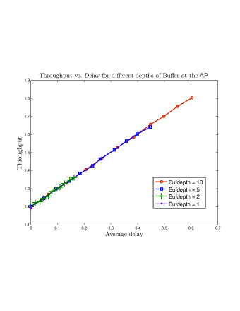
Result 6 (Impact of larger buffer depth): Increasing the buffer depth at increases the throughput. The increase in throughput comes at the cost of increased delay due to packet reordering. In order to understand the tradeoff between delay and throughput due to larger than one , and the probability we simulate the buffer of the with packets for 5 mobile nodes. All nodes always have packets for the , and in radio range of one another. Thus full-duplex exchange is always possible and can be broken only via virtual contention. Only type of contention allowed was virtual contention in the buffer of . For every , was ranged from 0 to 1. The had uniform traffic for all nodes with packets lined up in an arbitrary order. Figure 9 shows a plot of throughput vs. average delay (for the head of the buffer packet) for different buffer depths. A key finding that the throughput and average delay are linearly related. Larger can help in improving the throughput at the cost of delay. Also, it is often possible to obtain the same (throughput, average delay) pair for smaller by simply increasing the probabilty of reordering, .
The protocol description is now complete. In the next section, we consider an example topology to understand how all the proposed mechanisms in FD-MAC come in play.
4.7 State Transitions in FD-MAC
Consider the clique topology shown in Figure 4(c). Assume that there are four flows in the network, , , , . Four flows bring forth the possibility of two full-duplex scenarios and .
Figure 10 shows the mechanisms which allow the network to go from one mode to another. Each transition is enabled by the features introduced by the FD-MAC protocol. The three node network with clique topology can transition from one full-duplex mode i.e. to only through half-duplex modes. This is so because the first packet in two-way full-duplex exchange, as discussed in Section 4.4, is always a half-duplex packet. Suppose that network is in the mode . From this full-duplex mode, the network can transition to a half-duplex mode due to different reasons: (a) if at least one of or has no more packets in the buffer for the other, i.e. if(HOL or HOL), both the and naturally give up full-duplex mode (b) any of the DATA or ACK packets is not decoded right - failure in reception leads to purging of queue states of other nodes to start 802.11 type contention (c) the packets with as destination win the virtual contention resolution allows the network to break away from full-duplex entering a mode, and (d) wins the physical contention during the silent shared random backoff period, thus initiating .
All the half-duplex modes can switch among each other with the 802.11 protocol. Consider the half-duplex mode . From this mode the only possible transition to a full-duplex mode is . The mechanism of two-way setup is discussed in Section 4.4. The FD-MAC protocol therefore allows all modes to occur by switching between various modes through mechanisms introduced by FD-MAC, and some existing 802.11 capability.
The hidden node topology with two mobile nodes and an is shown in Figure 4(b). With and hidden with respect to each other, two full-duplex flows in addition to , are possible. They are , and . Each of four full-duplex modes, whether two-way exchange or otherwise start with a particular half-duplex mode. For instance is possible only if there exists as discussed in Section 4.5.
In order to ensure that transition to all full-duplex modes is possible, FD-MAC must ensure that the half-duplex mode needed to kick start it is possible. Half-duplex modes among themselves contend via 802.11 type of physical contention. The two-way full-duplex exchanges have a period of shared random backoff for other half-duplex modes to occur. Moreover they also have virtual contention resolution at the to allow different half-duplex modes. On the other hand , type of full-duplex, has always contending for the media after it finishes sending the ACK, thus allowing all other nodes to contend and establish a half-duplex communication with . Since all half-duplex modes are possible from any starting state. Consequently the snooping mechanism will allow all full-duplex modes too.
4.8 FD-MAC evaluations on WARP
In this section we evaluate the FD-MAC for a two node full-duplex exchange by implementing it on a real time full-duplex system designed using WARP. Figure 11 shows a full-duplex WARP node, with one transmit and one receive antenna.
The experimental set-up has two full-duplex nodes exchanging packets with each other. FD-MAC ensures setting up of the full-duplex upon discovering an opportunity to exchange packets in full-duplex mode. The buffer at both the nodes always had a head of line packet for the other. The evaluation compares the throughput of full-duplex against half-duplex (again implemented on WARP).
| SINR | Throughput | Throughput |
|---|---|---|
| of FD | of FD | HD |
| 9dB | 285 | 158 |
| 8dB | 276 | 165 |
| 7dB | 253 | 169 |
| 5dB | 269 | 151 |
The modulation used for transmission was QPSK.
Result 7 (Increase in throughput due to full-duplex): The encouraging result is that the throughput of full-duplex two-way exchange using FD-MAC is 70% higher than that of half-duplex for identical transmit power.
5 Discussion and Conclusions
We note that FD-PHY and FD-MAC are first real-time design and implementation of full-duplex physical and medium access layers, and thus expect many avenues to further optimize the system performance. Perhaps the most promising is a joint design of transmitted signal, canceling mechanisms and baseband processing on full-duplex nodes. We believe that this could lead to further self-interference suppression, and perhaps push the performance to near-perfect full-duplex systems.
Considering that full-duplex is still viewed skeptically by many, it is crucial to demonstrate real-time implementations showing fully operational network stacks. Towards that end, our work shows very promising results, creating a strong case for practical use of full-duplex in deployed networks.
References
- [1] P.D.L. Beasley, A.G. Stove, B.J. Reits, and B.O. As. Solving the problems of a single antenna frequency modulated CW radar. In IEEE International Radar Conference, 1990.
- [2] S.Chen, M.A. Beach, and J.P. McGeehan. Division-free duplex for wireless applications. In IEEE Electronics Letters, volume 34, pages 147–148, 1998.
- [3] W. Schacherbauer, A. Springer, T. Ostertag, C.C.W Ruppel, and R. Weigel. A flexible multiband frontend for software radios using high if and active interference cancellation. In IEEE International Microwave Simpossium, 2001.
- [4] A. Raghavan, E. Gebara, E. M. Tentzeris, and J. Laskar. Analysis and design of an interference canceller for collocated radios. IEEE Transactions on Microwave Theory and Techniques, 53(3498-3508), 2005.
- [5] D. W. Bliss, P.A. Parker, and A. R. Margetts. Simultaneous transmission and reception for improved wireless network performance. In Statistical Signal Processing, 2007. SSP ’07. IEEE/SP 14th Workshop on, pages 478–482, Aug. 2007.
- [6] B. Radunovic, D. Gunawardena, P. Key, A. Proutiereand N. Singh, V. Balan, and G. Dejean. Rethinking indoor wireless: Low power, low frequency, full duplex. Technical report, Microsoft Research, 2009.
- [7] J. I. Choi, M. Jain, K. Srinivasan, P. Levis, and S. Katti. Achieving single channel, full duplex wireless communications. In Proceedings of ACM Mobicom, 2010.
- [8] M. Duarte and A. Sabharwal. Full-duplex wireless communications using off-the-shelf radios: Feasibility and first results. In Proceedings of Asilomar Conference on Signals, Systems and Computers, 2010.
- [9] WARP MIMO Reference Design. http://warp.rice.edu/trac.
- [10] Constantine A. Balanis. Antenna Theory: Analysis and Design. John Wiley, third edition, 2005.