Hydrophobic droplets in amphiphilic bilayers: a coarse-grained mean-field theory study
Abstract
Hydrophobic molecules such as oils and certain drugs can be encapsulated between the two leaflets of an amphiphilic bilayer in both lipid and polymer systems. We investigate the case where the hydrophobic molecules are incompatible with the amphiphile tails and so form droplets. Using a coarse-grained mean-field model (self-consistent field theory, or SCFT), we find that droplets of a wide range of sizes have the same characteristic lens shape, and explain this result in terms of simple capillarity arguments, consistent with the measured variations of surface concentrations of amphiphile in the bilayer and in the monolayers that cover the droplet. We study the effect of the strength of the repulsion between the hydrophobic liquid and the amphiphile tails on the droplet shape, and find a gradual flattening of the droplet as is reduced. The droplet remains at least metastable even at very low values of . This is in contrast to the behavior as the length of the hydrophobic molecules is varied. Specifically, if these molecules are at least as long as the amphiphile tails, increasing their length further is found to have little effect on the droplet shape, while reducing their length below this value quickly causes the droplet to become unstable.
I Introduction
Amphiphilic molecules in solution form bilayers for a wide range of molecular architectures and experimental conditions Zasadzinski et al. (2001). These structures may form both from lipids Zidovska et al. (2009); Sorre et al. (2009) and from block copolymers Jain and Bates (2003); Discher et al. (1999); Discher and Eisenberg (2002), and are of great importance in a number of scientific disciplines. For example, lipid bilayers are an integral component of cells, where they form the outer membrane and also play a role in transport processes Sorre et al. (2009). The bilayer vesicles that form from block copolymers, on the other hand, are longer-lived and less permeable than their lipid counterparts Discher et al. (1999) making them promising candidates as vehicles for drug delivery Smart et al. (2010).
The encapsulation of hydrophobic molecules between the two leaflets of the bilayer has been a recurrent issue, and has been discussed in a variety of contexts, including drug carrier design, vesicle formation from inverse phase methods, and lipid distribution in cell membranes. In particular, it is often important to know whether the hydrophobic molecules form droplets or are spread more evenly throughout the bilayer center. For example, lipid cell membranes are often found to contain a second species of lipid Hamilton and Small (1981); Hamilton (1989); Hamilton et al. (1991), in surprisingly high concentrations Khandelia et al. (2010). The question then arises of whether this is due to the presence of small lipid domains within the bilayer, the existence of which has also been suggested to explain the formation of the lipid droplets seen in the center of cells Ohsaki et al. (2009); Zanghellini et al. (2010). Observations of such bilayer domains have indeed been reported in the biophysics literature Ferretti et al. (1999); May et al. (1986), and these structures have recently been seen in molecular dynamics simulations Khandelia et al. (2010). However, their probable small size and the existence of other lipid domains in the cell complicates the interpretation of experiments, and the issue is not fully resolved Hakumäki and Kauppinen (2000).
The formation of oil droplets in amphiphilic bilayers is also a problem of current interest in microfluidics, and has been observed in recent experiments on block copolymer systems Hayward et al. (2006). The aim of this research Hayward et al. (2006); Shum et al. (2008); Thiele et al. (2010) was to produce aqueous solutions of monodisperse vesicles from block copolymers in water-oil-water double emulsions by evaporating the oil. Here, the presence of oil droplets in the bilayers is undesirable, as it leads to unevenness in the vesicle wall.
In addition, the encapsulation of hydrophobic molecules in bilayers is of importance in the delivery of drugs using block copolymer vesicles Onaca et al. (2009); Meng et al. (2009); Li et al. (2010); Mueller et al. (2009). Although it might at first appear more natural to encapsulate a hydrophobic substance in the core of a spherical micelle, copolymer vesicles can offer certain advantages over these smaller structures. In particular, they can encapsulate both hydrophobic and hydrophilic compounds Qin et al. (2006); Zasadzinski et al. (2011). Furthermore, faster release of the hydrophobic compound can be obtained from vesicles Chen et al. (2010).
In this paper, we investigate how much information about hydrophobic droplets in bilayers can be obtained from a simple mean-field model of oil and amphiphile in solution. First, we will study the shape of the droplet and to what extent this varies with its size. We will then relate our results to capillarity arguments. Next, we will investigate the effect of the strength of the repulsion between the hydrophobic liquid and the amphiphile tails on the droplet shape. This question is of relevance to several of the situations described above, and our results will give some guidance as to how robust the phenomenon of droplet formation is expected to be in experiments. In addition, understanding the role of the interaction strength might allow an oil to be chosen to encourage or discourage Hayward et al. (2006) the formation of well-defined droplets. Finally, with similar objectives in mind, we will study the effect of the length of the hydrophobic molecules on the droplet shape and stability.
The paper is organized as follows. In the following section, we introduce the theoretical technique to be used, self-consistent field theory. We then present and discuss our theoretical results, and give our conclusions in the final section.
II Self-consistent field theory
Self-consistent field theory (SCFT) Edwards (1965) has been used with success to investigate the equilibrium structures formed in melts and blends of polymers Maniadis et al. (2007); Drolet and Fredrickson (1999); Matsen (2006), and may also be used to study metastable structures, Duque (2003); Katsov et al. (2004) and amphiphiles in solution Cavallo et al. (2006); Schuetz et al. (2011). It can be applied to a wide range of amphiphilic molecules, including simple homopolymers Werner et al. (1999), more complex copolymers Müller and Gompper (2002); Wang et al. (2010) and any given mixture of these Denesyuk and Gompper (2006). SCFT requires less computational power than simulation methods such as Monte Carlo, yet often provides comparably accurate predictions of the form of individual structures Cavallo et al. (2006); Wijmans and Linse (1995); Leermakers and Scheutjens (1990). Furthermore, as a coarse-grained model, with a simple description of the polymer molecules, it will allow us to capture the basic phenomenology of the system clearly.
We now give a brief introduction to SCFT, and refer the reader to reviews Matsen (2006); Fredrickson (2006); Schmid (1998) for a fuller presentation. A complete description of our calculations for amphiphiles in solution is given in a recent publication Greenall and Gompper (2011), and we present details only when our current system differs from that described there. SCFT models individual molecules as random walks in space, and so neglects fine details of their structure and packing Schmid (1998). An ensemble of many such molecules is considered. The interactions between the molecules are modeled by assuming that the blend is incompressible and by introducing contact potentials between the molecules Matsen (2006). The strengths of the potentials between the various species are specified by the Flory parameters Jones (2002). The computational difficulty of the problem is then sharply reduced by making a mean-field approximation Matsen (2006); that is, by neglecting fluctuations. This approximation is quantitatively accurate when the molecules are long Cavallo et al. (2006); Fredrickson (2006); Matsen (2006). In addition, SCFT can provide considerable qualitative insight into systems containing smaller molecules, such as lipid bilayers Katsov et al. (2004); Greenall and Gompper (2011) and aqueous solutions of copolymer Schuetz et al. (2011); Greenall et al. (2011).
We now discuss the application of SCFT to our system of amphiphile and oil in a solvent, which we model by a mixture of block copolymer with two incompatible homopolymers that represent the oil and the solvent respectively. Although such a mixture of polymers may appear quite simple, models of this level of complexity have been used to study a wide range of lipid and copolymer systems Katsov et al. (2004); Greenall et al. (2009a), and can capture broad phenomenology more clearly than more complicated theories. We take the copolymer to have a mean-squared end-to-end distance of , where is the monomer length and is the degree of polymerization Matsen (2006). One half of the monomers in this polymer are hydrophilic (type A) and the other half are hydrophobic (type B), so that the degrees of polymerization and for the A and B blocks are equal. We choose the same value of for the A homopolymer solvent as for the copolymers. Together with the values of and , this ensures that the amphiphile preferentially forms flat bilayer structures Greenall and Gompper (2011) for the interaction strength we will consider here. The degree of polymerization of the oil will be varied between and .
In this paper, we keep the amounts of copolymer and homopolymer in the simulation box fixed; that is, we work in the canonical ensemble. This will make it easier for us to access more complex structures such as droplets. Such structures are more difficult to stabilize in ensembles where the system is able to relax by varying the amount of the various species, and can require constraints to be imposed on the density profile Katsov et al. (2004).
For concreteness and to introduce the appropriate notation, we note that the SCFT approximation to the free energy of our system has the form
| (1) | ||||
where the are the mean volume fractions of the various components. The are the local volume fractions, with for the hydrophilic blocks, for the hydrophobic blocks, for the oil, and for the solvent. The first Flory parameter, , is set to , so that sharp, well-defined bilayers form. The other Flory parameters will be varied to study the effect of the nature of the oil on the droplet shape. is the total volume of the system, is the volume of a monomer, and is the SCFT free energy of a homogeneous system containing the same components. The details of the individual polymers enter through the single-chain partition functions . These are calculated Matsen (2006) from integrals over the propagators and , which are also used to compute the polymer density profiles Matsen (2006); Fredrickson (2006). Reflecting the fact that the molecules are modeled as random walks, the propagators satisfy modified diffusion equations with a field term that describes the polymer interactions. These equations are solved using a finite difference method Press et al. (1992) with step size of . We assume that the droplet is cylindrically symmetric and forms at the center of the system, and hence consider an effectively two-dimensional problem in a cylindrical calculation box. Reflecting boundary conditions are imposed at the edges of the system.
The derivation of the mean-field free energy also generates a set of simultaneous equations linking the values of the fields and densities. In order to calculate the SCFT density profiles for a given set of polymer concentrations, we begin by making an initial guess for the fields and solve the diffusion equations to calculate the propagators and then the densities corresponding to these fields. The new are then substituted into the simultaneous equations to calculate new values for the Matsen (2004). The procedure is repeated until convergence is achieved. We have checked that the algorithm converges to the same solution from different initial states and with different iteration speeds.
To form the structure we wish to study, a bilayer in the plane encapsulating a droplet at its center, a suitable initial guess for the must be made. It is important to note that it is not necessary to include any detailed information about the shape of the droplet or bilayer in this ansatz. Although, for the sake of speed, we will often use the final self-consistent fields corresponding to one bilayer-droplet system as initial guesses for a subsequent calculation, the initial form of the fields can be very simple. Specifically, to encourage the formation of the bilayer, it is sufficient to start the SCFT iteration with a simple square well for the hydrophobic block field . If is the approximate width of the bilayer, we set to a low value for , and a higher value elsewhere. The initial value of the hydrophilic block field can simply be set to zero, as the A and B blocks are connected and the above ansatz for is enough for an AB bilayer to form. The iteration for the field corresponding to the oil, , can similarly be initiated with a square well potential. The potential is set to a low value in a cylindrical region at the center of the system (, ), with and much smaller than the radius of the simulation box.
We set the tension of a bilayer with no oil to zero, as this corresponds most closely to the experimental situation of a vesicle in solution. To find the zero-tension bilayer, we proceed as follows Greenall et al. (2009a). First, we calculate the free-energy density of a (one-dimensional) box containing an infinite planar aggregate in solvent. The volume of the simulation box is then varied in the direction perpendicular to the bilayer surface, keeping the volume fraction of copolymer fixed (at ), until the box size with the minimum free-energy density is found. This scheme was introduced to mimic the behavior of a system of many aggregates Greenall et al. (2009a, b), which minimizes its free energy by varying the number of aggregates and hence the volume (‘box size’) occupied by each. Equivalently, this procedure allows us to prepare a bilayer under zero tension. Decreasing the box size at constant copolymer volume fraction reduces the amount of amphiphile in the system and so thins the bilayer, which corresponds to stretching it parallel to its surface. Conversely, increasing the box size thickens the bilayer, which is physically equivalent to compressing it. The bilayer found for the box size where the free energy is at a minimum is one that is neither too stretched nor too compressed and has no contributions to the free energy from polymer chains that are forced into unfavorable configurations.
This calculation is then used to fix the size of the cylindrical box in the -direction to , so that , where . The radius of the box is set to , to allow droplets of a wide range of sizes to be studied.
III Results and discussion
In this section, we study the shape and size of the droplets in detail for a single set of system parameters. Then we relate the droplet shape to the bilayer and monolayer tensions and amphiphile concentrations. Finally, we investigate how the droplet shape and stability depends on the nature and size of the oil molecules.
III.1 Droplet shape.
To begin, we calculate the density profiles for bilayer-encapsulated droplets of various sizes. We focus on a system with oil molecules that are half the size of the amphiphiles, so that . The interaction strength between the hydrophobic B-block of the amphiphile and the oil is set to . The effect of varying this quantity will be investigated later. Given that the strength of the repulsion between the A and B blocks of the amphiphile has already been set to , we no longer have complete freedom in our choice of the final Flory parameter, . If we assume that is related to the polarizabilities of the two polymer species by , where is a constant of proportionality Schmid (2011), we find that is given in terms of the other two interaction strengths by
| (2) |
and is therefore set to , where we choose the negative root to give a moderate incompatibility between the oil and the solvent.
Starting with the tensionless bilayer described above, we compute the density profiles of bilayer-encapsulated droplets for a range of oil volume fractions between and . The first of these values corresponds to the smallest droplet that could be stabilized in our calculations. In Figure 1, we show the density profiles for (a) the amphiphile and (b) the oil for an intermediate-sized droplet with . Figure 1a clearly shows the splitting of the amphiphile bilayer into two thin monolayers to incorporate the droplet. In Figure 1b, we plot the density profile of this lens-shaped droplet, and see also that a significant amount of oil remains between the two leaflets of the bilayer in the region surrounding the drop. This feature appears as horizontal gray lines on either side of the droplet in the density plot of Figure 1b, and is a result of the relatively weak repulsion between the hydrophobic block and the oil.

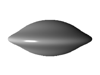
To help visualize the droplets, we show a ray-traced plot of the droplet surface (defined as the locus of points where ) in Figure 2. The overall lens shape of the droplet is clearly visible, as is the slight rim where the edge of the droplet meets the oil remaining in the bilayer.

III.2 Surface concentrations and tensions.
In order to gain more detailed insight into the droplet shapes, we plot cuts through the droplet surface for a range of droplet sizes from the smallest to the largest (see Figure 3). If we assume that no long-range forces act in the system, that the bending rigidity of the membrane can be neglected, and that the pressure inside the droplet is constant, both the upper and lower halves of the droplet will have a spherical cap shape Léger and Joanny (1992) in order to obey the Laplace law Rowlinson and Widom (1982); Landau and Lifshitz (1987). The expected shape for these cuts shown in Figure 3 is then a section of a circle, with the contact angle (see inset) determined by the mechanical equilibrium of the surface tensions along the contact line Léger and Joanny (1992). We indeed find that this shape gives a very good fit to the data for all droplet shapes (Figure 3), with a slight deviation in the rim region shown in Figure 2, where the droplet spreads out slightly between the two amphiphile leaflets instead of forming a perfect cusp. In addition, the contact angle calculated from the fits is the same for all droplet sizes to the accuracy of the calculations, and is given by .
To understand how the presence of the bilayer leads to the formation of these lens-shaped droplets, and to illustrate some other features of the density profiles plotted in Figure 1, we now plot a series of cuts through the density profiles of the various species. In Figure 4a, we show a cut in the -direction (perpendicular to the bilayer) through the density profiles of all species at the edge of the system containing the smallest droplet studied. This plot shows the state of the bilayer as far away from the droplet as possible. In Figure 4b, we show the corresponding plot for the bilayer in the system with the largest droplet. First, we note that the two plots are very similar and that the bilayer is not strongly distorted by the presence of the droplet. We will return to this point in a more quantitative fashion later on. Second, we see that a small but significant amount of oil remains in the center of the bilayer. Furthermore, the density profile of the oil shows a clear peak at the interface between the hydrophilic A and hydrophobic B blocks. This is because both and are smaller than , the repulsion between the two blocks of the amphiphile. A thin film of oil therefore forms in this region to protect these two strongly incompatible species from each other.

A clear contrast is seen between the density profiles of the bilayer a long way from the droplet, and those of the monolayer that covers the droplet. These latter profiles, calculated at the center of the system (), are plotted in Figure 4c (for the smallest droplet) and d (for the largest droplet). We note that, in both these cases, the maximum values of the density profiles of the A and B blocks of the amphiphile are lower than in Figure 4a and b. This is because the monolayer has to be stretched and thinned to cover the droplet, lowering the surface amphiphile concentration. In addition, the difference between the profiles for the smallest and largest droplets is much more marked than in the case of the bilayer. In particular, the amphiphile concentration in the monolayer covering the largest droplet (Figure 4d) is noticeably lower than in that covering the smallest droplet (Figure 4c), showing that the monolayer must be further stretched to encapsulate more oil. Furthermore, the monolayer in Figure 4d is more symmetric with respect to its inner and outer leaflets than that in Figure 4c, and the peak values of the A- and B-block concentrations are much closer. The reason for this is that the surface of the larger droplet is flatter, and the monolayer that encloses it is quite close to that which would form at a planar oil-solvent interface.

We now present a more quantitative discussion of the amphiphile density profiles. To begin, we integrate the bilayer and monolayer density profiles (Figure 4) in the -direction, including both hydrophilic and hydrophobic blocks. Specifically, we calculate
| (3) | ||||
is then the surface density of (half) the bilayer at the edge of the system (), while is the monolayer surface density at the center of the system (). The amount of amphiphile remaining in the bulk is low, so that its contribution to the surface densities is very small. and are calculated for all droplet sizes studied and are plotted against each other in Figure 5a. As would be expected from the profiles shown in Figure 4, the monolayer surface density varies over a wider range than the corresponding quantity for the bilayer, as the amphiphilic molecules are spread out more and more thinly in the monolayer as the droplet size increases. Furthermore, and are linearly related for a wide range of droplet sizes, with deviations from linearity only being seen for the higher surface densities corresponding to very small droplets. To understand this behavior, we relate and to the corresponding surface energies. First, we note that the amphiphile in our system acts as a surfactant, separating the solvent from the oil in the droplet and bilayer. Then, we assume that adding amphiphile linearly reduces the surface tension from its value in the absence of amphiphile, , so that . Here, is a constant of proportionality and for the tensions and densities at the system edge and for those at the droplet surface. Balancing these two tensions at the rim where the droplet meets the bilayer, as shown in the inset to Figure 3, we find also that . Combining this with our expressions for and , we have
| (4) |
From the slope of the straight line in Figure 5a, we find that , so that , in excellent agreement with our independent measurement of from the cross-sections in Figure 3. This shows the validity of the force balance argument, and also confirms our use of the same proportionality constant in our expressions for and . To check our linear formula for , we have also calculated, using Equation 1, the free energy density of a flat oil-containing bilayer with the profile shown in Figure 4a. Similar calculations are performed for all values of . We then plot the quantity (the free energy density measured with respect to that of the homogeneous solution with the same composition) as a function of the surface concentration . As can be seen from Figure 5b, decreases linearly with for all but the very smallest droplets, confirming our simple model for the surface energy . We note that the free energy density as calculated from Equation 1 includes a contribution from the solvent region as well as from the bilayer itself. However, this is likely to have a relatively small effect on the variation of , as the bulk amphiphile concentration changes very little with droplet size.
Both plots show some deviation from linearity for the smallest two or three droplet sizes considered. For the plot of the two surface concentrations in Figure 5a, the deviation comes from the increasing relative importance of the rim around the edge of the droplet (Figure 2), which means that a simple force balance argument based on a well-defined contact angle is less valid. The slight breakdown of linearity in Figure 5b may be due to the fact that the droplet is nearing its lower size limit and the free energy density is dropping more rapidly as the bilayer relaxes towards the flat state.
III.3 Nature and size of the oil molecules.
Having established a basic picture of droplet formation in our system, we now turn our attention to the question of how the nature and size of the oil molecules affects the shape and stability of the droplets. First, we investigate the effect of changing the Flory parameter determining the strength of the interaction between the oil and the hydrophobic blocks of the amphiphile. This corresponds to changing the chemical nature of the oil while keeping the length of the oil molecules constant. We keep the same type of amphiphiles as used in the preceding section, so that and are unchanged. However, as noted earlier, the three Flory parameters cannot be varied completely independently Schmid (2011), and must be recalculated according to Equation 2 for each value of . The volume fraction of oil is set to . In Figure 6, we plot the outlines of the droplets formed as is decreased from (the value used in our earlier calculations) to in steps of . The droplet with is that with the most rounded shape and the greatest thickness in the -direction. As is lowered to , the droplet spreads outward slightly into the bilayer and becomes thinner, as the oil becomes more compatible with the hydrophobic blocks of the amphiphile. The spreading effect here is rather small, suggesting that, above a certain , the droplet shape is relatively insensitive to the nature of the oil and retains its characteristic lens form. As is reduced further, the droplet continues to spread. However, the amount by which the droplet thickness falls due to each reduction of by gradually increases, until we obtain an almost flat structure at . It is interesting to note that, even for this very weak repulsion between the oil and the hydrophobic blocks, the droplet remains at least metastable.

The results shown in Figure 6 differ somewhat from the classical problem of the spreading of a single droplet Léger and Joanny (1992), as our droplet is in equilibrium with a film of oil in the bilayer, which grows in thickness, taking material from the droplet, as the oil becomes less incompatible with the hydrophobic B-blocks. This is particularly clear for the lowest value of considered. Here, the oil concentration in the bilayer is so high that our definition of the droplet surface as the locus of points at which now includes the oil film as an extension of the droplet.
Finally, we study the effect of the size of the oil molecules on the droplet shape. Returning to our original set of Flory parameters, with , we consider the following values of the oil polymerization index: , , (the original value), and , and plot the droplet outlines in Figure 7. As above, . For the largest three values of , the droplet shape changes rather little. It simply shrinks slightly as is lowered, as this change reduces the repulsion between the oil and the hydrophobic sections of the amphiphile so that more material leaks out of the droplet into the oil film.

However, as is lowered further, to , a sharp change occurs in the droplet shape. The thickness of the droplet in the -direction is now significantly greater, while its radius is smaller. It is difficult to interpret this result in terms of the simple force balance arguments used earlier. This is because the rim feature, which was previously a small perturbation on droplets whose shape could be represented by two joined spherical caps Léger and Joanny (1992), is now a much more significant part of the droplet, since the small oil molecules penetrate more effectively into the bilayer. We speculate that the elongated shape of this droplet may be a precursor to its eventual splitting into two smaller monolayer-wrapped droplets, such as those recently studied by Kusumaatmaja and Lipowsky in the context of membranes in contact with several fluids Kusumaatmaja and Lipowsky (2011). In any case, it certainly seems that the simple single-droplet solution to SCFT becomes unstable around . If we reduce below this value, no solution to the SCFT equations can be found using our current methods, and our algorithm slows down considerably even for .
IV Conclusions
Using a coarse-grained mean-field approach (self-consistent field theory) we have modeled several aspects of the structure of hydrophobic droplets encapsulated between the two leaflets of an amphilic bilayer. First, we have found that droplets of a range of sizes have the same simple lens shape that would be expected from simple capillarity arguments. We have explained both this shape and the amphiphile concentrations in different regions of the system by considering the balance of the surface tensions around the edge of the droplet.
Next, we studied the effect of the oil parameters on the droplet shape. We found that, although reducing the incompatibility causes the droplet to flatten and spread outwards into the bilayer, it remains at least metastable even for very low . There appears to be no clear threshold value of for droplet solutions to SCFT to exist. The droplets are also relatively insensitive to changes in the oil molecule length. In fact, provided these molecules are longer than the hydrophobic part of the amphiphile, their length has little effect on the droplet shape. These observations provide some evidence that droplet formation is a relatively robust effect and may therefore be a reasonable explanation for phenomena such as the inclusion of significant amounts of a second lipid species in lipid bilayers Khandelia et al. (2010). Furthermore, the formation of droplets even in our simple model indicates that this might be quite a general phenomenon and that hydrophobic domains such as those seen in the molecular dynamics simulations of Khandelia et al. Khandelia et al. (2010) might be observed in a variety of systems.
The current work opens a number of interesting perspectives that could be discussed within the framework of self-consistent field theory. First, our free energy calculations could be extended, to find the parameter range where the oil will form a droplet rather than spreading. Second, the question of whether an optimum droplet size exists could be addressed, perhaps by using a range of system sizes or by considering the stability of a droplet with respect to two smaller droplets. We could also study how likely the droplet is to split off from the bilayer, for example by comparing the free energies of the bilayer-encapsulated droplet and a system of a droplet covered by a monolayer in coexistence with a bilayer. Finally, droplets formed from a second species of amphiphile could be studied, to bring our calculations closer to the problem of lipid domains in bilayers Khandelia et al. (2010); Hakumäki and Kauppinen (2000).
V Acknowledgements
M.J.G. gratefully acknowledges funding from the EU under an FP7 Marie Curie fellowship.
References
- Zasadzinski et al. (2001) J. A. Zasadzinski, E. Kisak, and C. Evans, Curr. Opin. Colloid Interface Sci. 6, 85 (2001).
- Zidovska et al. (2009) A. Zidovska, K. K. Ewert, J. Quispe, B. Carragher, C. S. Potter, and C. R. Safinya, Langmuir 25, 2979 (2009).
- Sorre et al. (2009) B. Sorre, A. Callan-Jones, J. B. Manneville, P. Nassoy, J. F. Joanny, J. Prost, B. Goud, and P. Bassereau, Proc. Natl. Acad. Sci. U.S.A 106, 5622 (2009).
- Jain and Bates (2003) S. Jain and F. S. Bates, Science 300, 460 (2003).
- Discher et al. (1999) B. M. Discher, Y. Y. Won, D. S. Ege, J. C. M. Lee, F. S. Bates, D. E. Discher, and D. A. Hammer, Science 284, 1143 (1999).
- Discher and Eisenberg (2002) D. E. Discher and A. Eisenberg, Science 297, 967 (2002).
- Smart et al. (2010) T. P. Smart, A. J. Ryan, J. R. Howse, and G. Battaglia, Langmuir 26, 7425 (2010).
- Hamilton and Small (1981) J. A. Hamilton and D. M. Small, Proc. Natl. Acad. Sci. U.S.A. 78, 6878 (1981).
- Hamilton (1989) J. A. Hamilton, Biochemistry 28, 2514 (1989).
- Hamilton et al. (1991) J. A. Hamilton, D. T. Fujito, and C. F. Hammer, Biochemistry 30, 2894 (1991).
- Khandelia et al. (2010) H. Khandelia, L. Duelund, K. I. Pakkanen, and J. H. Ipsen, PLoS ONE 5, e12811 (2010).
- Ohsaki et al. (2009) Y. Ohsaki, J. Cheng, M. Suzuki, Y. Shinohara, A. Fujita, and T. Fujimoto, Biochim. Biophys. Acta 1791, 399 (2009).
- Zanghellini et al. (2010) J. Zanghellini, F. Wodlei, and H. H. von Grünberg, J. Theor. Biol. 264, 952 (2010).
- Ferretti et al. (1999) A. Ferretti, A. Knijn, E. Iorio, S. Pulciani, M. Giambenedetti, A. Molinari, S. Meschini, A. Stringaro, A. Calcabrini, I. Freitas, et al., Biochim. Biophys. Acta 1438, 329 (1999).
- May et al. (1986) G. L. May, L. C. Wright, K. T. Holmes, P. G. Williams, I. C. P. Smith, P. E. Wright, R. M. fox, and C. E. Mountford, J. Biol. Chem. 261, 3048 (1986).
- Hakumäki and Kauppinen (2000) J. M. Hakumäki and R. A. Kauppinen, Trends in Biochemical Sciences 25, 357 (2000).
- Hayward et al. (2006) R. C. Hayward, A. S. Utada, N. Dan, and D. A. Weitz, Langmuir 22, 4457 (2006).
- Shum et al. (2008) H. C. Shum, D. Lee, I. Yoon, T. Kodger, and D. A. Weitz, Langmuir 24, 7651 (2008).
- Thiele et al. (2010) J. Thiele, A. R. Abate, H. C. Shum, S. Bachtler, S. Förster, and D. A. Weitz, Small 6, 1723 (2010).
- Onaca et al. (2009) O. Onaca, R. Enea, D. W. Hughes, and W. Meier, Macromol. Biosci. 9, 129 (2009).
- Meng et al. (2009) F. Meng, Z. Zhong, and J. Feijen, Biomacromolecules 10, 197 (2009).
- Li et al. (2010) D. Li, C. Li, G. Wan, and W. Hou, Colloids Surf. A 372, 1 (2010).
- Mueller et al. (2009) W. Mueller, K. Koynov, K. Fischer, S. Hartmann, S. Pierrat, T. Basché, and M. Maskos, Macromolecules 42, 357 (2009).
- Qin et al. (2006) S. Qin, Y. Geng, D. E. Discher, and S. Yang, Adv. Mater. 18, 2905 (2006).
- Zasadzinski et al. (2011) J. A. Zasadzinski, B. Wong, N. Forbes, G. Braun, and G. Wu, Curr. Opin. Colloid Interface Sci. 16, 203 (2011).
- Chen et al. (2010) W. Chen, F. Meng, R. Cheng, and Z. Zhong, J. Controlled Release 142, 40 (2010).
- Edwards (1965) S. F. Edwards, Proc. Phys. Soc. 85, 613 (1965).
- Maniadis et al. (2007) P. Maniadis, T. Lookman, E. M. Kober, and K. O. Rasmussen, Phys. Rev. Lett. 99, 048302 (2007).
- Drolet and Fredrickson (1999) F. Drolet and G. H. Fredrickson, Phys. Rev. Lett. 83, 4317 (1999).
- Matsen (2006) M. W. Matsen, Soft Matter (Wiley-VCH, Weinheim, 2006), chap. 2.
- Duque (2003) D. Duque, J. Chem. Phys. 119, 5701 (2003).
- Katsov et al. (2004) K. Katsov, M. Müller, and M. Schick, Biophys. J. 87, 3277 (2004).
- Cavallo et al. (2006) A. Cavallo, M. Müller, and K. Binder, Macromolecules 39, 9539 (2006).
- Schuetz et al. (2011) P. Schuetz, M. J. Greenall, J. Bent, S. Furzeland, D. Atkins, M. F. Butler, T. C. B. McLeish, and D. M. A. Buzza, Soft Matter 7, 749 (2011).
- Werner et al. (1999) A. Werner, M. Müller, F. Schmid, and K. Binder, J. Chem. Phys. 110, 1221 (1999).
- Müller and Gompper (2002) M. Müller and G. Gompper, Phys. Rev. E 66, 041805 (2002).
- Wang et al. (2010) J. F. Wang, K. K. Guo, L. J. An, M. Müller, and Z. G. Wang, Macromolecules 43, 2037 (2010).
- Denesyuk and Gompper (2006) N. A. Denesyuk and G. Gompper, Macromolecules 39, 5497 (2006).
- Wijmans and Linse (1995) C. M. Wijmans and P. Linse, Langmuir 11, 3748 (1995).
- Leermakers and Scheutjens (1990) F. A. M. Leermakers and J. M. H. M. Scheutjens, J. Colloid Interface Sci. 136, 231 (1990).
- Fredrickson (2006) G. H. Fredrickson, The Equilibrium Theory of Inhomogeneous Polymers (Oxford University Press, Oxford, 2006).
- Schmid (1998) F. Schmid, J. Phys.: Condens. Matter 10, 8105 (1998).
- Greenall and Gompper (2011) M. J. Greenall and G. Gompper, Langmuir 27, 3416 (2011).
- Jones (2002) R. A. L. Jones, Soft Condensed Matter (Oxford University Press, Oxford, 2002).
- Greenall et al. (2011) M. J. Greenall, P. Schuetz, S. Furzeland, D. Atkins, D. M. A. Buzza, M. F. Butler, and T. C. B. McLeish, Macromolecules 44, 5510 (2011).
- Greenall et al. (2009a) M. J. Greenall, D. M. A. Buzza, and T. C. B. McLeish, J. Chem. Phys. 131, 034904 (2009a).
- Press et al. (1992) W. H. Press, B. P. Flannery, S. A. Teukolsky, and W. T. Vetterling, Numerical Recipes in C (Cambridge University Press, Cambridge, 1992), 2nd ed.
- Matsen (2004) M. W. Matsen, J. Chem. Phys. 121, 1938 (2004).
- Greenall et al. (2009b) M. J. Greenall, D. M. A. Buzza, and T. C. B. McLeish, Macromolecules 42, 5873 (2009b).
- Schmid (2011) F. Schmid, in Handbook of Multiphase Polymer Systems, edited by A. Boudenne (John Wiley and Sons, Chichester, 2011), chap. 3.
- Léger and Joanny (1992) L. Léger and J. F. Joanny, Rep. Prog. Phys. 55, 431 (1992).
- Rowlinson and Widom (1982) J. S. Rowlinson and B. Widom, Molecular Theory of Capillarity (Clarendon Press, Oxford, 1982).
- Landau and Lifshitz (1987) L. D. Landau and E. M. Lifshitz, Fluid Mechanics (Pergamon Press, Oxford, 1987), 2nd ed.
- Kusumaatmaja and Lipowsky (2011) H. Kusumaatmaja and R. Lipowsky, Soft Matter 7, 6914 (2011).