Intraband electron focusing in bilayer graphene
Abstract
We propose an implementation of a valley selective electronic Veselago lens in bilayer graphene. We demonstrate that in the presence of an appropriately-oriented potential step, low-energy electrons radiating from a point source can be re-focused coherently within the same band. The phenomena is due to the trigonal warping of the band structure that leads to a negative refraction index. We show that the interference pattern can be controlled by an external mechanical strain.
pacs:
68.65.Pq, 72.80.Vp, 73.20.At, 73.22.Pr, 73.23.Ad, 73.40.-c1 Introduction
Since its first experimental isolation [1, 2] graphene has had a profound impact on the solid state community. The past year has seen reinvigorated experimental and theoretical investigations of bilayer graphene, as sufficiently-clean samples have been fabricated to probe the low-energy spectrum [3]. A key conclusion of these investigations is that mechanical distortion as well as electron-electron interaction can lead to profound changes in the topology of the band structure and to symmetry breaking in the electronic system [4, 5, 6]. In recent years, new ideas in electron optics have utilized the exotic electronic structure of graphene and other novel materials such as topological insulators. Electron lenses utilizing negative refraction [7, 8, 9, 10] and valley-polarized electron beam splitters [11, 12, 13, 14] among others have been proposed to manipulate electron beams in mesoscopic devices. Apart from the manipulation of the valley degree of freedom, graphene devices have already been proposed for spin polarized electron beam engineering using magnets [15], and for spatial separation of electrons and holes using normal-superconducting-normal junctions [16].
Unlike 2DEGS (two-dimensional electron gas) in more conventional semiconductors [17, 18], which require a magnetic field to provide the focussing of electrons and imaging of the interference pattern of injected electrons is hindered by the fact that the 2DEG is often buried inside a heterostructure [19], graphene-based devices can be self-focussing and their interference patterns are exposed on the surface. In the present manuscript we propose an electron-optical device, whose valley-dependent interference pattern can be controlled by strain. By analogy with conventional 2DEGS, where the control of focussing by an external magnetic field leads to sensitive magnetic field sensors even at room temperature [20], our graphene-based device forms a basis for a sensitive detector of strain.
2 Electron Focusing in Novel Materials
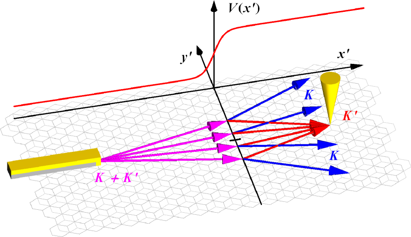
Focusing of electrons in graphene by a planar junction has first been proposed by Cheianov and coworkers [7]. In their proposal, particles are focused due to the fact that in the valence band, the group velocity points in the opposite direction to the wavevector. Hence electrons emitted from a point source on one side of a junction converge on the other side at a focal point, thereby realizing a Veselago lens [21, 22]. Circular junctions have also been investigated recently in single layer [8] and bilayer [23] graphene, where apart from the focal point, a hierarchy of caustics was discovered and described using the semiclassical approach of catastrophe optics [24]. Later it was pointed out that warping of the band structure [25] can also induce a focusing effect even when particles on the two sides of the junction are in the same band [9]. This was demonstrated with the hexagonally warped surface states of the three dimensional topological insulator [26]. In this work we propose a flat interface setup (shown in Fig. 1) that can focus electrons in bilayer graphene due to the trigonal warping [25] of the band structure. In this section we review some aspects of electron optics with regards to focusing particles by a flat interface.
For a particle incident on the barrier with wavevector and group velocity , the refractive index at the barrier is defined by the states that conserve the momentum parallel to the interface and propagate away from the interface. Let and denote the wavevector and group velocity of the transmitted/reflected particles respectively. If the velocities make an angle with the normal of the barrier then the refractive index is
| (1) |
In general, depends on the direction of .
The intraband focusing effect of a planar interface is closely related to the concave geometry of the -energy contours of the dispersion relation. It can be shown that electrons radiating from a point source into a small region in -space will be focused on the other side of the junction if and only if the curvatures of the energy contours on the two sides at the corresponding -wavevectors differ in sign. If this holds around the -vectors aligned with the optical axis, that is for rays that are nearly perpendicular to the interface, then the different signs of the curvatures result in a negative refractive index, which is however not a necessary condition for focusing if we move away from the optical axis. In particular, if the -contours are locally symmetric to the direction of the optical axis, then a simple, direct relation can be formulated between the refractive index for these rays and the curvatures on the two sides [9]:
| (2) |
where is the chemical potential on the incoming side of the junction and is the chemical potential on the other side of the junction. It also follows that around the optical axis, the negative sign of is needed for the focusing phenomenon. In Fig. 2 we show the trajectory of a single particle hitting a planar potential step in a bilayer graphene sample. (The barrier coincides with the -axis.) A classical trajectory can be parametrized by which determines all the remaining angles.
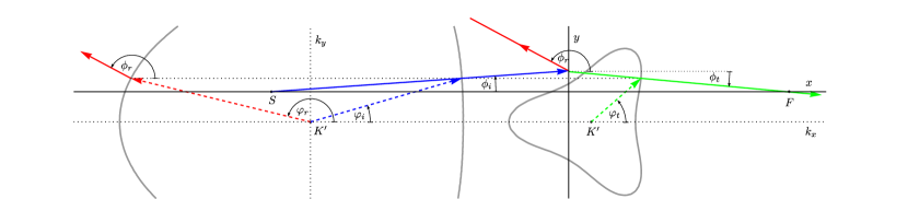
If a point source is situated at , then on the other side of the interface, a generic trajectory has the form
| (3) |
Some of the refracted rays touch each other at certain points. The sets of such points are called caustics, which are envelopes of a family of rays at which the density of rays is singular. In the classical theory of geometrical optics, this singularity is unphysical, however, the results of the semiclassical catastrophe optics [27] agrees well with the quantum mechanical treatment, which predicts a finite particle density with local maxima [24]. The focal point of particles corresponds to the global maximum of a cusp type caustic, which evolves into two fold type caustics. The coordinates of these curves can be obtained by differential geometry:
| (4) |
In order to describe the system quantum mechanically, one has to solve the Schrödinger equation on both sides of the junction and match the solutions at the boundary. The boundary conditions can be derived from the Schrödinger equation by applying it for an infinitesimally narrow stripe containing the junction. In the case of the model Hamiltonian used in this work, these conditions require the wavefunction to be smooth and the same for its first derivative with respect to the direction perpendicular to the junction. This can be satisfied with 2 planewave-like solutions of the homogeneous Schrödinger equation on either side of the junction. For a given , which must be conserved during the scattering process, there always exist 1 or 2 propagating waves and 1 or 0 decaying wave, giving always exactly 2 solutions on either sides needed to satisfy the boundary conditions. By solving this system of equations, we obtain the coefficients for the reflected and refracted rays matched to the incident ray. Since all the calculations can be extended in a straightforward manner for several rays, for the sake of simplicity, wherever applicable, we will assume that we only have one refracted wave propagating to the right direction. To calculate the density of particles, the contributions of all the refracted rays with the corresponding transmission amplitudes were summed up in the far field approximation. By the summation of the rays, a homogeneous distribution of the source electrons in is assumed.
3 Focusing in Bilayer Graphene
The central idea of our work is to use bilayer graphene with a potential step for focusing electrons, where particles remain in the same band. As we will demonstrate, this idea retains all the neat features of earlier setups [7, 9], including focusing and high transmission, and it even incorporates the idea of valley-dependent electron beam manipulation [11, 12, 26].
We start with the Hamiltonian of the system under consideration
| (5) |
where are the momentum operators and for valley and for . The material parameters of bilayer graphene and are defined among others in Ref. [28]. For very low energies ( meV), the complex parameter describes symmetry breaking due to the electron-electron interaction [4], but it also describes the external mechanical strain [5] for higher energies as well. The relation between and the mechanical distortion of the lattice can be formulated as
| (6) |
where is a real constant describing mechanical properties of the lattice, are the principal values of the strain tensor , and is the angle between the principal axes and coordinate axes . In the strain tensor, and are the coordinate-indexes and denote displacements from the equilibrium positions. In the expression (6) we neglect the interlayer shear shift. The potential describes a potential step that is sufficiently smooth on the atomic scale so that it does not introduce inter-valley scattering, and we can also neglect a term proportional to the gradient of the potential that arises in the Schrieffer-Wolff transformation in the derivation of (5) [25, 29]. We assume to have the form
| (7) |
i.e. the potential on the two sides of the step is constant and and the barrier makes an angle with the crystallographic direction (-axis). It is convenient to introduce a coordinate system where is defined by the planar potential step, and the source is sitting on the axis , which means that and and also and make an angle denoted by . We do not take into account a gap term in the Hamiltonian that accounts for the electrostatic asymmetry of the two graphene layers, since this would not alter the main message of the present work. We also neglect second nearest neighbour hopping in the individual graphene planes that has negligible effect on the results presented here. In the absence of the potential the spectrum of (5) has been studied in [25, 5]. For low energies, depending on the value of , the spectrum consists of four or two massless Dirac cones, whereas at higher energies, the band structure merges to form only a single pocket per valley. A typical energy scale of this model is the Lifshitz energy , which defines the Lifshitz transition of the band structure’s topology from multiple pockets to a single pocket in the absence of strain (). Since the Lifshitz energy is quite small, it was difficult to gain experimental data from energies below it until recently [3].
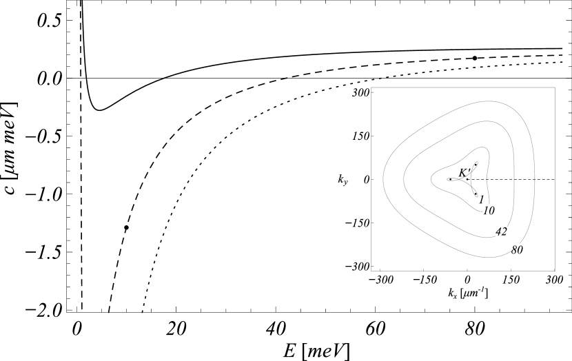
As shown in the previous section, focusing is controlled by the curvature of the band structure. If on the two sides of the potential step there exist regions in the -space on the given energies with overlapping projections to the dimension parallel with the junction, and for these corresponding -regions the curvature of the dispersion relation has different sign, then the system can focus electrons. In Fig. 3 we present the curvature of the dispersion curve of the considered model as the function of energy along the direction for different values of . It is clear that the curvature in the absence of changes sign roughly at . This energy scale is still sufficiently small compared to the direct inter layer hopping [25, 28] , that is it falls in the energy range where the two band model (5) is still valid. Since a changing can produce a large change in the energy of zero curvature, one can study the focused electrons in bilayer graphene samples with a planar potential step, and yield information about the value of , even in samples that are only moderately gated ( meV).
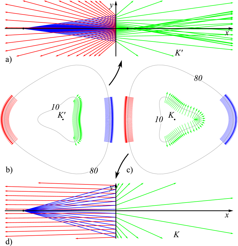
Our setup also has the capability of separating electrons in different valleys, without the need for an unrealistic potential barrier height of around , as in previous graphene based electron optical setups [11, 14]. This is demonstrated in Fig. 4, where we follow the classical trajectories of several particles emitted from a point source, in real and in -space for the case of undistorted samples, with the interface aligned on the -axis i.e. and . It is clear from the figure that electrons from the two valleys behave differently. Particles in valley disperse upon passing the barrier, while those in valley gather in a focus point on the other side. If the barrier is not aligned with the crystallographic orientation of the lattice, then in general there will be two or three foci each gathering particles from different valleys as shown in Fig. 5.
One key ingredient that is not captured by the ray tracing analysis is the transmission probability of particles reaching the junction. This can be calculated by evaluating first the expectation values of the current operator along the -axis. Then the transmission probability will be the ratio of the current carried by the refracted wave in the direction to that of the incoming wave also projected to . The reflection probability can be calculated on a similar basis from the reflected wave. Note that the evanescent waves do not carry current.

In Fig. 6 we show the transmission probability as the function the angle of incidence for different values of in the case of . Remarkably, the transmission probability is high and roughly independent of the angle of incidence for particles reaching the junction at a wide range of angles of incidence around the -axis. This is a beneficial result of scattering within the same band. For particles that change band during refraction at the junction, the transmission probability is reduced, is very sensitive to , and vanishes exactly for perpendicular incidence [23], unless gaps are induced by external gating [10].
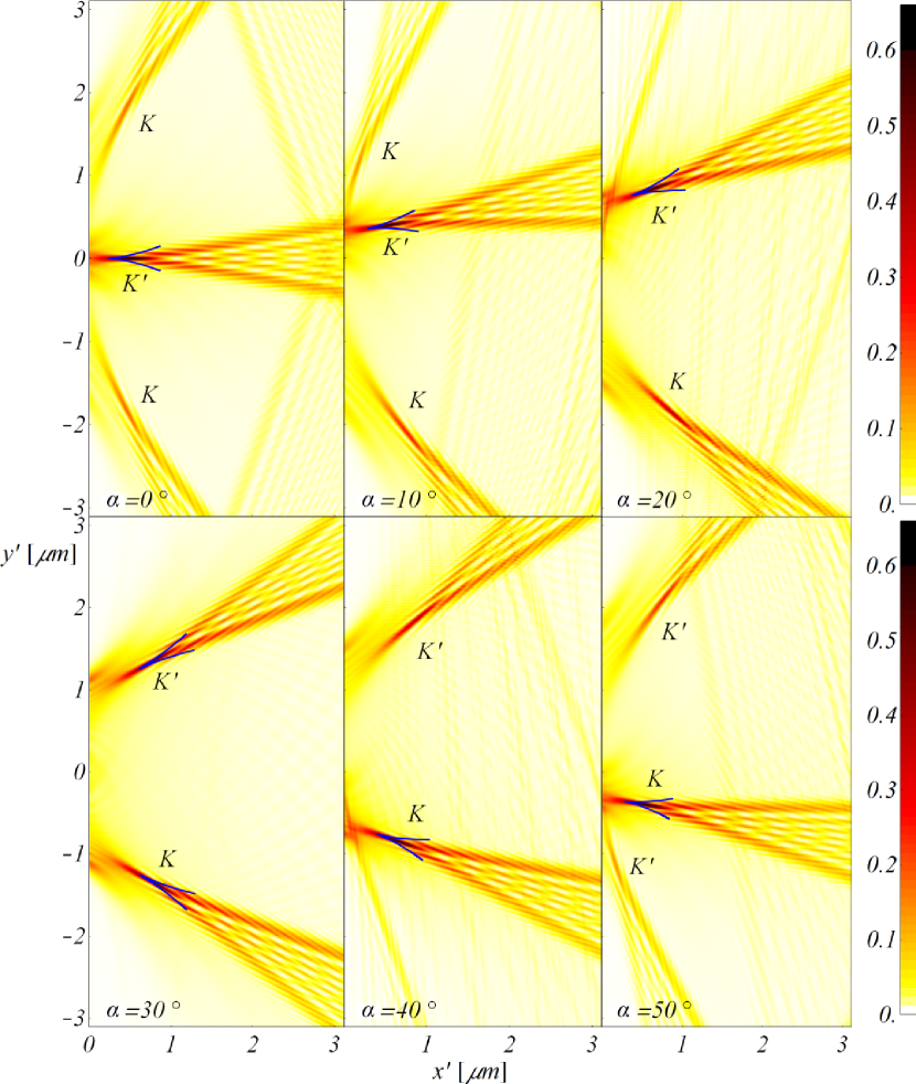
For finite , when the junction is not aligned with the -axis, the focus point will not remain on the -axis but will continuously move with . This is depicted in Fig. 5, where the total particle density is plotted with contributions from both valleys and for different values for . We also calculated the classical curves of the caustics using (4). In the figure, these curves are represented by blue lines, the crossing points of which approach neatly the maxima of the particle density as expected. There are two or three focus points each gathering particles either from the , or the valley.
4 Effects of broken symmetry
As shown in Ref. [4], the electron-electron interaction in bilayer graphene leads to a spontaneous breaking of the threefold rotational symmetry giving rise to a finite value of in the effective low-energy Hamiltonian (5). However in this description of the electron-electron interaction, the Fermi energy as well as the energy of the excitations around it need to be of the same order of magnitude as the Lifshitz energy ( meV), which is not the case discussed in this paper. Also, originating from the interaction can have very different values on the two sides of the junction, which are unknown. On the other hand, later, it was argued in Ref. [5] that mechanical distortion leads to the same low-energy effective theory, with a constant on a wide energy range. A key consequence of a finite is that depending on its value, the low energy spectrum of the system can undergo a topological phase transition. For small magnitudes of , the spectrum consists of four Dirac cones, while at larger , there are only two Dirac cones in the spectrum. The small value of the Lifshitz energy makes it difficult to infer directly the number of Dirac points. Therefore it is essential to seek indirect methods to determine the value of and hence the number of Dirac points.
As presented in Fig. 3, the curvature of the energy contours depends considerably on the value of . This suggests that the position of the focus point will be similarly sensitive.
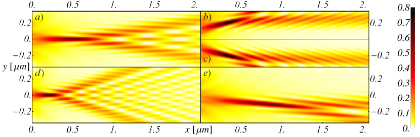
Indeed, this is clear from Fig. 7 where we show particle densities from valley for different values of . The most important information one can extract from this data is the position of the maxima that can be used to directly infer the value of the complex parameter .
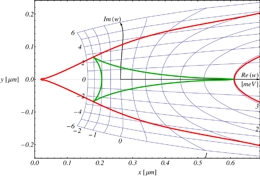
In Fig. 8, we show the semiclassical estimation for the position of the tip of the cusp caustic as the function of the real and imaginary part of for . From the expression (6), it is apparent that the imaginary phase of will be reflecting a direct relation to the geometrical deformation of the lattice. It is also worth mentioning that if is a multiple of , then is real, but if , then is purely imaginary, and otherwise it is a general complex number. Interestingly, if , then vanishes. This corresponds to a ’hydrostatic’ rescaling of the lattice and only affects the values of and . Based on the results of Ref. [5] and [31], it can be show that a distortion of 1% changes and just by a few percent and thus the effect on the diffraction pattern is negligible. On the other hand, we have shown that the position of the foci sensitively depends on the value of . Thus by experimentally investigating the focusing effect, one can measure the external strain present in the sample.
In clean systems, the most important factor that determines the lifetime of excitations is electron-phonon scattering. According to recent calculations [32, 33], the mean free path for excitations in the considered energy range around is of the order of microns, which is accessible by current experimental techniques [34].
5 Conclusion
In this paper, we investigated the anisotropic electron optics of bilayer graphene. We demonstrated that a moderate potential step can be used to focus electrons within the same band in a valley-selective manner with high transmission probability. We also investigated the effects of broken symmetry in the electronic structure due to mechanical distortion. The presented results clearly show that the proposed device can be used to determine symmetry breaking and extract indirect information about the low-energy topology of the band structure of bilayer graphene samples. These results are expected to form key ingredients in future device design, where one can envisage using bilayer graphene as building blocks for more complex electron-optical devices.
References
References
- [1] K. S. Novoselov, A. K. Geim, S. V. Morozov, D. Jiang, M. I. Katsnelson, I. V. Grigorieva, S. V. Dubonos, and A. A. Firsov. Two-dimensional gas of massless Dirac fermions in graphene. Nature, 438:197, 2005.
- [2] K. S. Novoselov, E. McCann, S. V. Morozov, V. I. Fal’ko, M. I. Katsnelson, U. Zeitler, D. Jiang, F. Schedin, and A. K. Geim. Unconventional Quantum Hall Effect and Berry’s phase of in bilayer graphene. Nature Physics, 2:177, 2006.
- [3] A. S. Mayorov, D. C. Elias, M. Mucha-Kruczyński, R. V. Gorbachev, T. Tudorovskiy, A. Zhukov, S. V. Morozov, M. I. Katsnelson, V. I. Fal’ko, A. K. Geim, and K. S. Novoselov. Interaction-driven spectrum reconstruction in bilayer graphene. Science, 333:860, 2011.
- [4] Y. Lemonik, I. L. Aleiner, Cs. Tőke, and V. I. Fal’ko. Spontaneous symmetry breaking and Lifshitz transition in bilayer graphene. Phys. Rev. B, 82:201408, 2010.
- [5] Marcin Mucha-Kruczyński, Igor L. Aleiner, and Vladimir I. Fal’ko. Strained bilayer graphene: Band structure topology and Landau level spectrum. Phys. Rev. B, 84:041404, 2011.
- [6] Diana A. Gradinar, Henning Schomerus, and Vladimir I. Fal’ko. Conductance anomaly near the Lifshitz transition in strained bilayer graphene. Phys. Rev. B, 85:165429, 2012.
- [7] Vadim V. Cheianov, Vladimir Fal’ko, and B. L. Altshuler. The focusing of electron flow and a Veselago lens in graphene junctions. Science, 315:1252, 2007.
- [8] József Cserti, András Pályi, and Csaba Péterfalvi. Caustics due to a negative refractive index in circular graphene junctions. Phys. Rev. Lett., 99:246801, 2007.
- [9] F. Hassler, A. R. Akhmerov, and C. W. J. Beenakker. Flat-lens focusing of electrons on the surface of a topological insulator. Phys. Rev. B, 82:125423, 2010.
- [10] Sunghun Park and H.-S. Sim. Berry phase and Veselago lens in a bilayer graphene junction. Phys. Rev. B, 84:235432, 2011.
- [11] J. L. Garcia-Pomar, A. Cortijo, and M. Nieto-Vesperinas. Fully valley-polarized electron beams in graphene. Phys. Rev. Lett., 100:236801, 2008.
- [12] J M Pereira Jr, F M Peeters, R N Costa Filho, and G A Farias. Valley polarization due to trigonal warping on tunneling electrons in graphene. J. Phys.: Cond. Matt., 21:045301, 2009.
- [13] D. S. L. Abergel and Tapash Chakraborty. Generation of valley polarized current in bilayer graphene. Applied Physics Letters, 95:062107, 2009.
- [14] Zhengfei Wang and Feng Liu. Manipulation of electron beam propagation by hetero-dimensional graphene junctions. ACS Nano, 4:2459, 2010.
- [15] Paolo Michetti, Patrik Recher, and Giuseppe Iannaccone. Electric field control of spin rotation in bilayer graphene. Nano Lett., 10:4463–4469, 2010.
- [16] S. Gómez, P. Burset, W. J. Herrera, and A. Levy Yeyati. Selective focusing of electrons and holes in a graphene-based superconducting lens. Phys. Rev. B, 85:115411, 2012.
- [17] H. van Houten, B. J. van Wees, J. E. Mooij, C. W. J. Beenakker, J. G. Williamson, and C. T. Foxon. Coherent electron focussing in a two-dimensional electron gas. Europhys. Lett., 5:721, 1988.
- [18] M.A. Topinka, R.M. Westervelt, and E.J. Heller. Imaging electron flow. Physics Today, 56:47, 2003.
- [19] A. M. Gilbertson, A. Kormányos, P. D. Buckle, M. Fearn, T. Ashley, C. J. Lambert, S. A. Solin, and L. F. Cohen. Room temperature ballistic transport in InSb quantum well nanodevices. App. Phys. Lett., 99:242101, 2011.
- [20] Katherine E. Aidala, Robert E. Parrott, Tobias Kramer, E. J. Heller, R. M. Westervelt, M. P. Hanson, and A. C. Gossard. Imaging magnetic focusing of coherent electron waves. Nature Physics, 3:464, 2007.
- [21] Viktor G Veselago. The electrodynamics of substances with simultaneously negative values of and . Soviet Physics Uspekhi, 10:509, 1968.
- [22] J. B. Pendry. Negative refraction makes a perfect lens. Phys. Rev. Lett., 85:3966, 2000.
- [23] Cs. Péterfalvi, A. Pályi, and J. Cserti. Electron flow in circular junctions of bilayer graphene. Phys. Rev. B, 80:075416, 2009.
- [24] Csaba Péterfalvi, András Pályi, Ádám Rusznyák, János Koltai, and József Cserti. Catastrophe optics of caustics in single and bilayer graphene: Fine structure of caustics. physica status solidi (b), 247:2949, 2010.
- [25] Edward McCann and Vladimir I. Fal’ko. Landau-level degeneracy and Quantum Hall Effect in a graphite bilayer. Phys. Rev. Lett., 96:086805, 2006.
- [26] Liang Fu. Hexagonal warping effects in the surface states of the topological insulator . Phys. Rev. Lett., 103:266801, 2009.
- [27] M. V. Berry and C. Upstill. Catastrophe optics: Morphologies of caustics and their diffraction patterns. Prog. Opt., 18:257, 1980.
- [28] Mikito Koshino. Electronic transport in bilayer graphene. New J. Phys., 11:095010, 2009.
- [29] C. J. Poole. On the applicability of the two-band model to describe transport across junctions in bilayer graphene. Solid State Commun., 150:632, 2010.
- [30] J.F. Nye and J.H. Hannay. The orientations and distortions of caustics in geometrical optics. Optica Acta: International Journal of Optics, 31:115, 1984.
- [31] Marcin Mucha-Kruczyński, Igor L. Aleiner, and Vladimir I. Fal’ko. Landau levels in deformed bilayer graphene at low magnetic fields. Solid State Communications, 151:1088, 2011.
- [32] K. M. Borysenko, J. T. Mullen, E. A. Barry, S. Paul, Y. G. Semenov, J. M. Zavada, M. Buongiorno Nardelli, and K. W. Kim. First-principles analysis of electron-phonon interactions in graphene. Phys. Rev. B, 81:121412, 2010.
- [33] K. M. Borysenko, J. T. Mullen, X. Li, Y. G. Semenov, J. M. Zavada, M. Buongiorno Nardelli, and K. W. Kim. Electron-phonon interactions in bilayer graphene. Phys. Rev. B, 83:161402, 2011.
- [34] Yuanbo Zhang, Victor W. Brar, Feng Wang, Caglar Girit, Yossi Yayon, Melissa Panlasigui, Alex Zettl, and Michael F. Crommie. Giant phonon-induced conductance in scanning tunnelling spectroscopy of gate-tunable graphene. Nature Physics, 4:627, 2008.