Prototyping scalable digital signal processing systems for radio astronomy using dataflow models
Abstract
There is a growing trend toward using high-level tools for design and implementation of radio astronomy digital signal processing (DSP) systems. Such tools, for example, those from the Collaboration for Astronomy Signal Processing and Electronics Research (CASPER), are usually platform-specific, and lack high-level, platform-independent, portable, scalable application specifications. This limits the designer’s ability to experiment with designs at a high-level of abstraction and early in the development cycle.
We address some of these issues using a model-based design approach employing dataflow models. We demonstrate this approach by applying it to the design of a tunable digital downconverter (TDD) used for narrow-bandwidth spectroscopy. Our design is targeted toward an FPGA platform, called the Interconnect Break-out Board (IBOB), that is available from the CASPER. We use the term TDD to refer to a digital downconverter for which the decmation factor and center frequency can be reconfigured without the need for regenerating the hardware code. Such a design is currently not available in the CASPER DSP library.
The work presented in this paper focuses on two aspects. Firstly, we introduce and demonstrate a dataflow-based design approach using the dataflow interchange format (DIF) tool for high-level application specification, and we integrate this approach with the CASPER tool flow. Secondly, we explore the trade-off between the flexibility of TDD designs and the low hardware cost of fixed-configuration digital downconverter (FDD) designs that use the available CASPER DSP library. We further explore this trade-off in the context of a two-stage downconversion scheme employing a combination of TDD or FDD designs.
Gindraft=false \authorrunningheadSANE ET AL. \titlerunningheadDATAFLOW MODELS FOR RADIO ASTRONOMY DSP \authoraddrS. S. Bhattacharyya, Department of Electrical and Computer Engineering, and Institute for Advanced Computer Studies, University of Maryland, College Park, MD, 20742, USA. (ssb@umd.edu) \authoraddrJ. Ford, National Radio Astronomy Observatory, Green Bank, WV, 24944, USA. (jford@nrao.edu) \authoraddrA. I. Harris, Department of Astronomy, University of Maryland, College Park, MD, 20742, USA. (harris@astro.umd.edu) \authoraddrN. Sane, Department of Physics, and Center for Solar-Terrestrial Research, New Jersey Institute of Technology, Newark, NJ, 07102, USA. (nimish.sane@njit.edu)
1 Introduction
Key challenges in designing digital signal processing (DSP) systems employed in the field of radio astronomy arise from the need to process very large amounts of data at very high rates arriving from one or more telescopes. It is also desirable to have scalable and reconfigurable designs for shorter development cycles and faster deployment. Moreover, these designs should be portable to different platforms to keep up with advances in new hardware technologies. However, conventional design methodologies for signal processing systems in the field of radio astronomy focus on custom designs that are platform-specific. Such designs, by virtue of being platform-specific, are highly specialized, and thus difficult to retarget. Traditional design approaches also lack high-level platform-independent application specifications that can be experimented with, and later ported to and optimized for various target platforms. This limits the scalability, reconfigurability, portability, and evolvability across varying requirements and platforms of such DSP systems.
A model based approach for design and implementation of a DSP system can effectively exploit the semantics of the underlying models of computation. This facilitates precise estimation and optimization of system performance and resource requirements (e.g., see (Bhattacharyya et al., 2010)). Though approaches for scalable and reconfigurable design based on modular field programmable gate array (FPGA) hardware and software libraries have been developed (e.g., see (Parsons et al., 2005, 2006; Szomoru, 2011; Nallatech website, ; Lyrtech website, )), they do not provide forms of high-level abstraction that are linked to formal models of computation.
We propose an approach using DSP-oriented dataflow models of computation to address some of these issues (Lee and Messerschmitt, 1987). Dataflow modeling is extensively used in developing embedded systems for signal processing and communication applications, and electronic design automation (Bhattacharyya et al., 2010). Our design methodology involves specifying the application in the dataflow interchange format (DIF) (Hsu et al., 2005) using an appropriate dataflow model. This application specification is transformed into an intermediate, graphical representation, which can be further processed using graph transformations.
The DIF tool allows designers to verify the functional correctness of the application, estimate resource requirements, and experiment with various dataflow graph transformations, which help to analyze or optimize the design in terms of specific objectives. The DIF-based dataflow specification is then used as a reference while developing a platform-specific implementation. We show how formal understanding of the dataflow behavior from the software prototype allows more efficient prototyping and experimentation at a much earlier stage in the design cycle compared to conventional design approaches.
We demonstrate our approach using the design of a tunable digital downconverter (TDD) that allows fine-grain spectroscopy on narrow-band signals. A primary motivation behind a TDD design is to support changes to the targeted downsampling ratio without requiring regeneration of the corresponding hardware code. Development of such a TDD is a significant contribution of this work. We compare our TDD with the fixed-configuration digital downconverter (FDD) designs that use the current DSP library from the Collaboration for Astronomy Signal Processing and Electronics Research (CASPER) (see (CASPER Website, )). We explore trade-offs between the flexibility offered by TDD designs and their hardware cost. A TDD is particularly useful since our target FPGA hardware platform — interconnect break-out board (IBOB) (Parsons et al., 2006) — does not have the feature of storing more than one configurations (also referred to as “personalities”) and dynamically loading one of them, unlike some of the CASPER hardware platforms of a later generation. A single reconfigurable TDD design also simplifies code management when compared to multiple static designs.
We must emphasize that this paper describes a dataflow-based design flow for prototyping radio astronomy DSP systems. This approach is not restricted to any particular tool or hardware platform. We intend to demonstrate it by developing a high-level DIF prototype that uses dataflow formalisms and generating a hardware implementation using CASPER tools from this DIF prototype. The proposed approach is not intended to replace the CASPER tools. It offers enhancements to the existing CASPER design flow. However, this does not restrict its use to only the CASPER tools.
The organization of the rest of this paper is as follows. Section 2 describes a TDD application. Section 3.1 describes dataflow modeling in detail, along with some of the relevant forms of dataflow (dataflow models) that are employed in practice. A reader who is familiar with dataflow formalisms may skip this section. Section 3.2 provides information about the DIF tool, while Section 3.3 highlights some of the relevant prior work. Section 4 explains how a DIF prototype can be used to develop a hardware implementation. Section 5 provides a summary and our conclusions.
2 Tunable Digital Downconverter
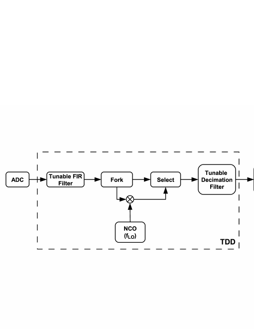
In the DSP literature, the terms downsampling and decimation are often used interchangeably. In this paper, a decimator refers to a block that simply decimates or downsamples the input signal without any other processing (e.g., see Fig. 1(a) and (b)). The ratio of the sampling rate at the input of a decimator to that at its output is referred to as its decimation factor. A decimator is generally preceded by an anti-aliasing filter (Vaidyanathan, 1990). In this paper, we refer to such a combined structure, consisting of a filter and decimator, as a decimation filter (e.g., see Fig. 2(a) and (b)). In a polyphase implementation of a decimation filter, such as the one we use in our implementation, this structure is implemented as a single computing block (Vaidyanathan, 1990). We refer to the system or application that employs a decimator or decimation filter, possibly with other blocks such as mixers and filters, as a digital downconverter, and in particular, a FDD or TDD (e.g., see Fig. 3 and Fig. 4). The decimation factor of a decimation filter, TDD, or FDD refers to that of the decimator in it.
Fig. 3 shows a block diagram of a TDD application. An -bit analog-to-digital converter (ADC) receives a baseband input IF signal of bandwidth MHz and samples it at the sampling rate of giga-samples/second (GS/s). The internal design of the ADC block is such that consecutive time samples, where each sample is an -bit fixed point number, are output on the eight -bit buses at the same clock pulse. This results in mega-samples/second (MS/s) on each of the outputs of the ADC block. Correspondingly, all the downstream blocks also have input and output ports. Thus, there are connections between any two blocks shown in Fig. 3 that are directly connected. We have not shown all connections in detail for the sake of clarity and simplicity.
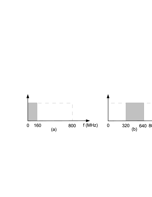
The TDD subsystem, identified by the dotted box in Fig. 3, extracts a subband of the input signal with a user-specified center frequency () and bandwidth (), downconverts it to a baseband, and then downsamples it to the Nyquist rate. For example, Fig. 5 shows two of the possible configurations of and and the corresponding frequency bands that are extracted. The output of the TDD can be used by the downstream DSP blocks. For example, a possible scheme can have a TDD implementation on the IBOB. The downstream DSP blocks may include functions such as polyphase filtering and fast Fourier transform. These blocks can be implemented on a different hardware. This is possible using a communication link between two hardware boards that behaves as a FIFO buffer. An Ethernet link using x auxiliary user interface (XAUI) ports available on the IBOB is an example of such a link.
During narrow-band observations, the Nyquist sampled output of the TDD will be analyzed with an existing spectrometer. The same number of spectral channels will thus provide proportionately greater spectral resolution as compared to analyzing the entire input bandwidth. Our TDD design supports integer decimation factors between and . The choice of these values stems purely from the initial specification of the Green Bank Ultimate Pulsar Processing Instrument (GUPPI) (Ford and Ray, 2010). This should be considered simply as a demonstrative implementation. The approach presented in this paper does not restrict the design in any way from having different specifications. The valid values of corresponding to the selected can vary so as to span the entire MHz IF input.
As shown in Fig. 3, the TDD includes a tunable finite impulse response (FIR) filter. If the desired output is a baseband signal, then the FIR filter simply acts as a low-pass filter. Also, in this case, the fork (which can be viewed as a dataflow version of a signal splitting block) and select (which is similar to a multiplexer) blocks are configured to route the output of the FIR filter directly to the tunable decimation filter (TDF), bypassing the mixer.
If the desired output is not a baseband signal, the FIR filter acts as a bandpass filter (BPF). The cut-off frequencies for this BPF are set using the specified parameter configuration ( and ). In this case, the output of the BPF is fed to a real mixer, which translates it into a baseband signal. The local oscillator, with a frequency , is implemented as a numerically controlled oscillator (NCO). The frequency, , is dependent on the value of and . The output of the mixer is then fed to the TDF, which downsamples its input depending upon the specified or decimation factor. We have used this scheme in order to have a real-valued TDF output.
Such a TDD, which was originally designed for the GUPPI at the National Radio Astronomy Observatory (NRAO), Green Bank, finds its use in the spectrometers currently under development for the Green Bank telescope (GBT) and 20m telescope at the NRAO, Green Bank.
3 Background
3.1 Dataflow Modeling
Dataflow modeling involves representing an application using a directed graph , where is a set of vertices (nodes) and is a set of edges. Each vertex in a dataflow graph is called an actor, and represents a specific computational block, while each directed edge represents a first-in-first-out (FIFO) buffer that provides a communication link between the source actor and the sink actor . A dataflow graph edge can also have a non-negative integer delay, , associated with it, which represents the number of initial data values (tokens) present in the associated buffer. Dataflow graphs operate based on data-driven execution, where an actor can be executed (fired) whenever it has sufficient amounts of data (numbers of “samples” or data “tokens”) available on all of its inputs. Typically, in DSP-oriented data flow design environments, the execution of a dataflow graph can be thought of as that of a “globally asynchronous locally synchronous” (GALS) system (Suhaib et al., 2008; Shen and Bhattacharyya, 2009).
During each firing, an actor consumes a certain number of tokens from each input and produces a certain number of tokens on each output. When these numbers are constant (over all firings), we refer to the actor as a synchronous dataflow (SDF) actor (Lee and Messerschmitt, 1987). For an SDF actor, the numbers of tokens consumed and produced in each actor execution are referred to as the consumption rate and production rate of the associated input and output, respectively. If the source and sink actors of a dataflow graph edge are SDF actors, then the edge is referred to as an SDF edge, and if a dataflow graph consists of only SDF actors, and SDF edges, the graph is referred to as an SDF graph.
For a dataflow graph edge , and , denote its source and sink actors, and if is an SDF edge, then denotes the production rate of the output port of that is connected to , and similarly, denotes the consumption rate of the input port of that is connected to .
A static schedule for a dataflow graph is a sequence of actors in that represents the order in which actors are fired during an execution of .
Usually, production and consumption information — in particular, the number of tokens produced and consumed (production/consumption volume) — by individual firings is characterized in terms of individual input and output ports so that each port of an actor can in general have a different production or consumption volume characterization. Such characterizations can involve constant values as in SDF (Lee and Messerschmitt, 1987) (as described above); periodic patterns of constant values, as in cyclo-static dataflow (CSDF) (Bilsen et al., 1996); or more complex forms that are data-dependent (e.g., see (Buck, 1993; Bhattacharya and Bhattacharyya, 2000; Murthy and Lee, 2002; McAllister et al., 2004; Plishker et al., 2008)). A meta-modeling technique called parameterized dataflow (PDF) allows limited forms of dynamic behavior (Bhattacharya and Bhattacharyya, 2000) in terms of run-time changes to dataflow graph parameters. The Boolean dataflow (BDF) (Buck, 1993) and core functional dataflow (CFDF) (Plishker et al., 2008) models are highly expressive (Turing complete) dynamic dataflow models. We have explained SDF, CSDF, and PDF models in greater detail later in this section.
Apart from DIF, which we have mentioned earlier, there are various existing design tools with their semantic foundations in dataflow modeling, such as Ptolemy (Pino et al., 1995), LabVIEW (Johnson, 1997), StreamIt (Thies et al., 2002), CAL (Eker and Janneck, 2003), PeaCE (Kwon et al., 2004), Compaan/Laura (Stefanov et al., 2004), and SysteMoc (Haubelt et al., 2007). Dataflow-oriented DSP design tools typically allow high-level application specification, software simulation, and possibly synthesis for hardware or software implementation (Bhattacharyya et al., 2010).
3.1.1 Synchronous Dataflow
An SDF graph is characterized by its compile-time predictability through the statically known consumption and production rates, as defined above. Fig. 6 shows a simple SDF graph having actors W, X, Y, and Z (shown as circles or vertices of the graph). Each edge (an arrow in the figure connecting a pair of actors) is annotated with the number of tokens produced on it by the source actor and that consumed from it by the sink actor during every invocation of the source and sink actors, respectively. For example, actor X can be fired when there are at least two tokens on its input. Whenever actor X is fired, it consumes two tokens from its input buffer, and produces three tokens onto the output buffer connected to Y and two tokens onto the output buffer connected to Z.
3.1.2 Cyclo-static Dataflow
Many signal processing applications involve behaviors in which production and consumption rates may change during run-time. In some cases, these changes may, however, be known at compile-time. For example, consider the CSDF graph shown in Fig. 1(a), which has a decimator actor M in it. This actor consumes one token from its input on each invocation, but produces a token onto its output only on every fourth invocation. This behavior has been depicted using the varying production volumes denoted by . The numbers of tokens produced by the decimator M follow this cyclic pattern with a period of . This sequence of varying production volumes, though not leading to constant output rates like an SDF actor, is still completely deterministic and known at the compile-time. This kind of dataflow behavior, where actors exhibit token production and consumption volumes (in terms of tokens per firing on specific actor ports) that are either constant or expressible as cyclic sequences of constant volumes, is referred to as CSDF. Thus, CSDF can be viewed as a generalization of SDF in which token production and consumption volumes may be different across different firings of an actor, but follow cyclic patterns that are completely specified at the compile-time.
We refer readers to (Bilsen et al., 1996) for more details on the CSDF model. As shown in Fig. 1(a) and Fig. 1(b), it may be possible to transform a CSDF actor into an SDF actor. In general, when feedback loops are present in a dataflow graph, such a transformation may introduce deadlock, and therefore should be attempted with caution. Such a transformation, when admissible (not leading to deadlock), generally has trade-offs in terms of relevant metrics including latency, throughput, and code size. More detailed comparisons between the SDF and CSDF models of computation are presented in (Parks et al., 1995) and (Bhattacharyya et al., 2000).
3.1.3 Parameterized Dataflow
Though CSDF provides enhanced expressive power compared to SDF, it is still unable to specify patterns in token consumption and production volumes that are not fully known at compile time. A meta-modeling technique called PDF has been proposed to represent certain kinds of dataflow application dynamics (Bhattacharya and Bhattacharyya, 2000). This model can be used with any arbitrary dataflow graph format that has a well-defined notion of a schedule iteration. For example, the PDF meta-model, when combined with an underlying SDF model, results in the PSDF (parameterized synchronous dataflow) model. A PSDF graph behaves like an SDF graph during one schedule iteration, but can assume different configurations across different schedule iterations.
The PDF meta-model supports semantic and syntactic hierarchy. Syntactic hierarchy is used, as in other forms of dataflow, to decompose complex designs in terms of smaller components. On the other hand, semantic hierarchy in PDF is used to apply specific features in the meta-model that are associated with dynamic parameter reconfiguration. A hierarchical actor that encapsulates such semantic hierarchy in PDF is called a PDF subsystem. A PDF subsystem in turn has three underlying graphs called the init, subinit, and body graphs, which interact with each other in structured ways. Intuitively, the init and subinit graphs can capture data-dependent, dynamic behavior at certain points during the execution of the graph and configure the body graph to adapt in useful ways to such dynamics. Intuitively, the init graph is designed to capture parameter configuration that is driven by higher, system-level processing, while the subinit graph is designed to capture the parameter changes occurring across different iterations of the corresponding body graph. The init graph can be used to dynamically configure parameters in the subinit graph, which, in general, executes more frequently relative to the init graph.
To further illustrate the PDF modeling technique, we consider the application example shown in Fig. 2(a). This example involves an FIR filter with filter taps or coefficients given by followed by a decimator with a tunable decimation factor of . The values of and are set either through a higher level system or user interface. We skip the details of this mechanism for the sake of simplicity and conciseness. Such behavior can be modeled using PDF with an underlying CSDF model. Such a modeling approach is referred to as the parameterized cyclo-static dataflow (PCSDF) model (Saha et al., 2006). Fig. 2(b) shows one of the possible PCSDF graphs corresponding to the application shown in Fig. 2(a). The subsystem DF is a PCSDF subsystem with its component graphs as shown in the figure. It can be seen here that the control actor in the DF.init graph of DF subsystem sets the required external and internal parameters, , and , respectively. This actor models the required parameter control through either a higher level system or some form of user interface. In this particular case, the DF.subinit graph is empty (in general, the init, subinit and body graph do not all have to be used for a given subsystem).
The PCSDF model allows CSDF actors for which the cyclic patterns of token production and consumption volumes can be parameterized in terms of their periods, the actual numbers of tokens consumed or produced in the cyclo-static sequences, or both. Intuitively, for a given configuration of application parameters, a PCSDF graph behaves as a CSDF graph. However, a PCSDF graph not only models all possible parameter configurations in a given application but also describes how they can be changed at run-time.
Such a model is of particular interest for modeling multirate DSP systems that exhibit parameterizable sample rate conversions. PCSDF allows designers to systematically explore design spaces across static, quasi-static, and dynamic implementation techniques. Here, by quasi-static implementation techniques, we mean techniques where relatively large portions of the associated software or hardware structures are fixed at compile-time with minor adjustments allowed at run-time (e.g., in response to changes in input data or operating conditions). A variety of quasi-static dataflow techniques are discussed, for example, in (Bhattacharyya et al., 2010).
3.2 The Dataflow Interchange Format
To describe dataflow applications for a wide range of DSP applications, application developers can use the DIF language, which is a standard language founded in dataflow semantics and tailored for DSP system design (Hsu et al., 2005). DIF provides an integrated set of syntactic and semantic features that help promote high-level modeling, analysis, and optimization of DSP applications and their implementations without over-specification. From a dataflow point of view, DIF is designed to describe mixed-grain graph topologies and hierarchies as well as to specify dataflow-related and actor-specific information. The dataflow semantic specification is based on dataflow modeling theory and independent of any design tool.
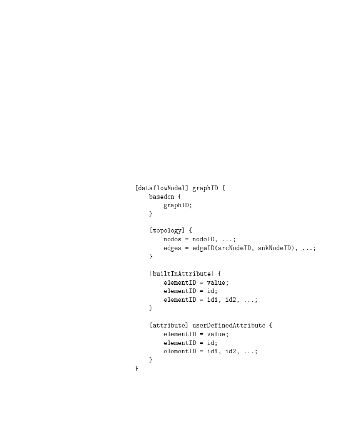
Fig. 7 illustrates some of the available constructs in the DIF language along with the syntax used for application specification. More details on the DIF language can be found in (Hsu et al., 2007). The topology block of the specification specifies the graph topology, which includes all of the nodes and edges in the graph. DIF supports built-in attributes such as interface, refinement, parameter, and actor, which identify specifications related to graph interfaces, hierarchical subsystems, dataflow parameters, and actor configurations, respectively. DIF also allows user-defined attributes, which have a similar syntax as built-in attributes except that they need to be declared with the attribute keyword.
The DIF language has been recently augmented with constructs for supporting topological patterns (Sane et al., 2010). Topological patterns allow concise specification of functional structures at the dataflow graph (inter-actor) level. They can effectively represent many of the flowgraph substructures that are pervasive in the DSP application domain (e.g. chain, ring, butterfly, etc.) to generate compact, scalable application representations. We direct readers to (Sane et al., 2010, 2011) for more information on the concept of topological patterns and how the DIF supports it.
To facilitate use of the DIF language, the DIF package (TDP) has been built (see Fig. 8). Along with the ability to transform DIF descriptions into manipulable internal representations, TDP contains graph utilities, optimization engines, verification techniques, a comprehensive functional simulation framework, and a software synthesis framework for generating C code (Hsu et al., 2005; Plishker et al., 2008). These facilities make TDP an effective environment for modeling dataflow applications, providing interoperability with other design environments, and developing and experimenting with new tools and dataflow techniques. Beyond these features, DIF is also suitable as a design environment for implementing dataflow-based application representations. Describing an application graph is done by listing nodes (actors) and edges, and then annotating dataflow specific information as well as other (non-dataflow) kinds of relevant information associated with actors, edges, and design subsystems.
The framework in DIF for simulation and functional verification of applications, which is based on CFDF semantics, allows application specifications in DIF to be used as executable references for rapid system prototyping and developing further platform-specific implementations. CFDF, which supports dynamic dataflow behaviors, allows flexible and efficient prototyping of dataflow-based application representations, and permits natural description of both dynamic and static dataflow actors. More information on CFDF semantics can be found in (Plishker et al., 2008).
3.3 Related Work
There exist high-end reusable, modular, scalable, and reconfigurable FPGA platforms such as the Berkeley Emulation Engine 2 (BEE2) (Chang et al., 2005), IBOB (Parsons et al., 2006), and UniBoard (Szomoru, 2011), which have been introduced specifically for DSP systems. These have been widely used for radio astronomy applications. The BEE2 uses SDF as a unified computation model for both the microprocessor and the reconfigurable fabric. It uses a high-level block diagram design environment based on The Mathworks’ Simulink and the Xilinx System Generator (XSG). This design environment, however, does not expose the underlying dataflow model. In particular, the designer has little or no scope to make use of the underlying dataflow model for experimentation (as mentioned earlier in Section 1). Also, the SDF model used for programming the BEE2 is a static dataflow model in that all the dataflow information is available at compile-time (i.e., before executing or running the application). Though this feature provides maximal compile-time predictability, it has limited expressive power. It does not allow for data-dependent, dynamic behavior, which is exhibited by many modern DSP applications, such as the TDD application introduced in Section 2 (see (Bhattacharyya et al., 2010) for more examples of such applications). Other forms of dataflow models that can capture more application dynamics with acceptable levels of compile-time predictability may better exploit the features offered by platforms such as the BEE2. We should, however, mention that the CASPER DSP library offers a software register block that can provide limited parameterization in the design. We have used this block extensively in our TDD design.
There are some other FPGA design solutions and tool flows available (e.g., those from Nallatech (Nallatech website, ), and Lyrtech (Lyrtech website, )). These, however, are commercial tools and do not provide open-source DSP software libraries like the CASPER. Also, CASPER tools support most of the Xilinx FPGA devices unlike these other commercial tools.
Model based approaches for designing large scale signal processing systems with a focus on radio telescopes have been previously studied (e.g., see (Alliot and Deprettere, 2004; Lemaitre and Deprettere, 2006; Lemaitre, 2008)). Several frameworks have been proposed for model based, high-level abstractions of architectures along with performance/cost estimation methods to guide the designer throughout the development cycle (see (Alliot and Deprettere, 2004)). However, the focus of these approaches has been on architecture exploration. There have also been attempts to derive implementation-level specifications starting from system-level specifications by segregating signal processing and control flow (see (Lee and Seshia, 2011) for more information on control flow) into an application specification and architecture specification, respectively (see (Lemaitre and Deprettere, 2006; Lemaitre, 2008)). However, the choice of models of computation has been made primarily from control flow considerations rather than dataflow considerations. These approaches, though relevant, do not specifically address the issue of high-level application specification for platform-independent prototyping and use of models of computation for abstraction of heterogeneous or hybrid dataflow behaviors. This issue is critical to efficient prototyping of high performance signal processing applications, which are typically dataflow dominated, and include increasing levels of dynamic dataflow behavior (e.g., see (Bhattacharyya et al., 2010)).
We address this issue using the CFDF model with underlying PSDF or PCSDF behavior and using it for system prototyping. We then show how platform-independent specifications based on this modeling technique can be used to efficiently develop platform-specific implementations.
4 Dataflow-based Design and Implementation of a TDD
We propose an approach for design and implementation of a TDD based on the dataflow formalisms discussed in Section 3.1 along with relevant capabilities of the DIF tool described in Section 3.2. Fig. 9 gives an overview of our dataflow based approach, which we now describe.
4.1 Modeling and Prototyping using DIF
We start with an application specification that describes the DSP algorithm under consideration (in this case, the TDD) along with proper input and output interfaces. The application is specified using the DIF language. This DIF specification consists of topological information about the dataflow graph — interconnections between the actors along with input and output interfaces. The DIF specification is a platform-independent, high-level application specification. The specification can be used, for example, to simulate the application, given the library of actors from which the specification is constructed.
Depending upon the application under consideration, the designer can select among a variety of dataflow models of computation in DIF to effectively capture relevant aspects of the application dynamics. It should be noted that the designer does not always need to specify the model in advance. The CFDF model can be used to describe individual modules (actors) in the application, and the DIF package can analyze the CFDF representation (CFDF modes, to be specific) of the actors, as specified by the designer through the actor code, and annotate the actors with additional dataflow information using various techniques for identifying specialized forms of dataflow behavior (e.g., see (Plishker et al., 2010)). This step requires the functionality of individual actors to be specified in CFDF semantics. The designer can use the existing blocks from the Java actor library in DIF or develop his or her own library of CFDF actors.
In terms of tunability, the key components of the TDD as seen from Fig. 3 are the tunable FIR filter, and decimation filter blocks. The tunable decimation filter (TDF) block is of particular interest, considering that it is the only multirate block in the system. Its behavior resembles that of the one described in Section 3.1.3. In view of this, we have identified PSDF and PCSDF as candidate dataflow models for efficient implementation of the targeted TDD system. For this system, we have to take into account the multiple inputs and outputs to actors, as mentioned in Section 2.
To illustrate details of the dataflow behavior of a decimator actor based on such specifications, we have shown one such decimator actor with inputs and outputs, and having a decimation factor of in Fig. 10(a) and Fig. 10(b). The decimator simultaneously receives consecutive samples from its inputs. It outputs every sixth input sample starting with the first input sample. Each of these output samples appears on a successive output of the decimator.
For the sake of simplicity and clarity, we have excluded the other single rate blocks from the application graphs in these figures. In our implementation, we extend this behavior for an actor with inputs and outputs. We have created a DIF prototype using PSDF and PCSDF as underlying models for equivalent CFDF representation of actor blocks. We have also developed a Java library of actors in DIF adhering to CFDF semantics for all of the blocks.
We then used DIF for software prototyping, analysis, and functional simulation. The DIF package uses the DIF specification to generate an intermediate graph representation, which can then be used as an input for further graph transformations including a scheduling transformation, which determines the schedule for an application. Here, by a schedule, we mean the assignment of actors to processing resources, and the execution ordering of actors that share the same resource. The functional simulation capabilities provided in DIF can be used to analyze and estimate buffer requirements in terms of the numbers of tokens accumulated on the buffers that correspond to dataflow graph edges. This provides an estimate of total memory requirements as well as specifications for individual buffers when porting the application to the targeted implementation platform.
Fig. 11 shows the TDD application graph generated using DIF. This is based on the TDD block diagram shown in Fig. 3 with addition of some actors that handle parameter configuration for the actors. We discard one of the two sets of outputs (more specifically, sine output) of the localOsc actor as we have employed a real mixer in our design. The complexity of the graph, which is increased due to multiple parallel edges between two actors, can easily be captured through a DIF specification that makes use of topological patterns. We have shown one of the possible specifications of the graph topology in DIF using topological patterns in Fig. 12.
For our design, we have used parameterized looped schedules (PLSs) (Ko et al., 2007) for PSDF and PCSDF models to determine the total buffer requirements. Using the TDD specification, we construct PLSs for the TDD application. Fig. 13(a) shows a PLS for a TDD application, where the decimator actor has the underlying SDF model, while Fig. 13(b) shows one in which the decimator actor employs the CSDF model. We have used the generalized schedule tree (GST) representation for the PLSs (Ko et al., 2007). An internal node of a GST denotes a loop count, while a leaf node represents an actor. The execution of a schedule involves traversing the GST in a depth-first manner, and during this traversal, the sub-schedule rooted at any internal node is executed as many times as specified by the loop count of that node. As annotated in these GSTs, loop counts p0, p1, and p2 are parameterizable. The loop count p0 is set to a user-specified number of iterations, while the loop counts p1 and p2 are tuned based upon the decimation factor as well as the underlying dataflow model for the decimator. Fig. 13(a) and (b), in particular, show values of the parameterizable loop counts set for a decimator with a decimation factor of . This PLS can be viewed as providing CFDF-based execution for the given PDF-based actor specification model.
Table 1 shows the total buffer requirements using PLSs shown in Fig. 13(a) and (b) for various configurations of decimation factors. Note that for a given configuration (setting of graph parameters), a PSDF or PCSDF graph behaves like an SDF or CSDF graph, respectively. It can be seen that for the SDF model, the total buffer requirements vary with the decimation factor, and this is due to input buffers to the TDD block that need to accumulate varying numbers of tokens. Thus, employing the PSDF model will require tuning buffer sizes for different decimation factors if one wants to provide for optimized buffer sizes in terms of graph parameters.
We have used the CASPER tool flow for developing our platform-specific implementation as explained later in Section 4.2. This implementation is targeted to an FPGA. Our objective here is to support tuning the decimation factor without regenerating hardware code. A dataflow buffer can be implemented using a FIFO or dual-port random access memory (RAM) block in the targeted FPGA device. The size of the available FIFO block can be set to , where . This gives limited control over setting the FIFO size, and may increase the resource utilization. At the same time, tuning the sizes of FIFO or dual-port RAM blocks is not possible during run-time. It is in general possible to set the size of a FIFO or dual-port RAM block to a maximum required value, and access only a part of it using a tunable address counter during run-time. This, however, again may lead to unnecessary increased resource utilization. The ADC output is of a streaming nature (data is produced or consumed at every clock cycle without any synchronization signal), as is the DSP subsystem downstream of the TDD.
In order to achieve the throughput constraint imposed by the maximum data rate of the ADC output stream, SDF buffers need to be pipelined, which is not efficient using RAM blocks. Thus, we use the CSDF model, which does not require tuning of dataflow buffer sizes to achieve the maximum throughput constraint, as observed from our DIF-based prototype. The TDD generates a synchronization or enable signal indicating a valid output data. This can be used as a clock to drive the downstream DSP system.
We use our DIF prototype as a reference while integrating the design with the current CASPER tool flow for the target implementation on the IBOB. Section 4.2 further elaborates on this approach along with implementation results.
4.2 Integration with the CASPER Tool Flow
The CASPER tool flow is based on the BEE_XPS tool flow (Parsons et al., 2006). This tool flow requires that an application be specified as a Simulink model using XSG (Parsons et al., 2006). Since there is no automated tool for transforming a DIF representation into an equivalent Simulink model, porting the DIF specification to Simulink/XSG requires manual transcoding of the DIF specification. This also requires implementing parameterizable actor blocks that are currently not available in the XSG, CASPER, or BEE_XPS libraries.
Each actor gets transformed into an equivalent functional XSG block. For each of the Simulink actor blocks, we provide a pre-synthesis parameterization that allows changing block parameters before hardware synthesis (see (Parsons et al., 2007) for more details on Simulink scripting). In order to implement our objective of tunability — post-synthesis parameterization — we use the software register mechanism in the BEE_XPS library to specify parameters that change during run-time (that is, after hardware code is generated, and depending upon user requirements.)
Software registers can be accessed and set during run-time from the TinyShell interface available for IBOB. This allows tuning TDD parameters without re-synthesizing the hardware each time the parameters change from the previous setting. Each block has an enable input signal. Through systematic transformations, an application graph in DIF can be converted into an equivalent Simulink/XSG model. We have developed an interface software package using C programs, and Bash and Python scripts to compute software register values for the required TDD configuration, and set these values on the IBOB over a telnet connection, which is used for remote access to the hardware platform at NRAO.
On the targeted FPGA device, we have employed the NCO using dual-port RAM blocks that are loaded with pre-computed sinusoidal signal values of the required precision. Each of these dual-port RAM blocks is used to simultaneously read sine and cosine values from both of its ports. The oscillator frequency is set using a software register, and depends upon the desired output signal band.
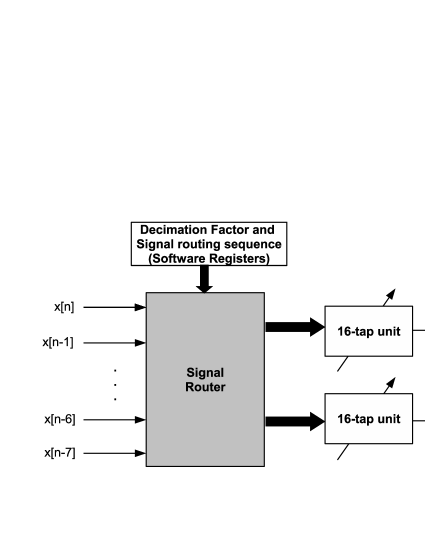
In our current implementation, the TDF block (see Fig. 3) can have up to filter taps. We have also implemented a tunable FIR filter block, which does not decimate, shown in Fig. 3. This block can have up to taps in our implementation. These, again, are set using software registers. Fig. 4(b) shows the schematic of a TDF. As shown in this figure, we have employed two filter banks (16-tap units) inside our design of a TDF block that operate in tandem to allow maximum throughput (that is, the maximum data rate of the ADC output stream). Hence, our TDF block has multiplication operations. As mentioned earlier, our TDF design employs a polyphase implementation as described in (Vaidyanathan, 1990). The software computes the sequence in which the input signals should be routed to an appropriate filter tap for a given decimation factor. This information is then fed to the signal routing scheme using software registers.
Table 2 shows results for the TDD implementation on the IBOB using the Xilinx EDK 7.1.2. We have used this hardware platform and tool for all of the experiments reported in the remainder of the paper. Design shows some of the device utilization parameters for a TDD that supports only baseband modes. This design does not include the tunable FIR filter, NCO, and mixer blocks shown in Fig. 3. Design is based on the block diagram of a TDD shown in Fig. 3. As evaluation metrics for hardware cost, we have used the utilization of FPGA slices, -input look-up tables (LUTs), and block RAM units, and the number of embedded multipliers. Note that neither of these two designs use any of the available embedded multipliers for multiplication. Designs and are modified versions of designs and , respectively, in that they employ embedded multipliers. It can be seen that using embedded multipliers does not provide significant improvements in hardware cost. We observe that use of embedded multipliers, in fact, needs to be accompanied by addition of extra latency in the design to achieve timing closure. We have been able to achieve maximum throughput using an implementation based on the PCSDF model.
4.3 Platform-specific Analysis using DIF
It is common to go back and forth between a high-level prototype and a corresponding platform-specific implementation while designing an embedded DSP system. Such alternation in design phases is common, for example, when one is developing a platform-specific library or tool flow. In support of such a design methodology, it is desirable for a high-level design tool to support platform-specific analysis. This can be achieved by annotating the high-level application specification with platform-specific implementation parameters, which are derived through device data sheets, experimentation or some combination of both.
DIF supports specifying user-defined actor parameters. We use this feature in DIF to annotate actors with two relevant implementation parameters — the latency constraint, and number of embedded multipliers. This allows estimating results based on the DIF prototype itself instead of determining them from the constructed design, which is generally time consuming. We have verified the accuracy of metrics estimated by our DIF model compared with actual hardware synthesis results that are shown in Table 2.
Developers of tool flows and DSP libraries can profile their library blocks to determine a wide variety of platform-specific implementation parameters. DIF can use such information to estimate implementation parameters at a high-level of abstraction, and earlier in the design cycle to help efficiently prune segments of the design space. Support for estimation of various platform-specific resources for different platforms is beyond the scope of this paper. It is, however, an important direction toward developing alternative model based design flows and open access tool flows for astronomical DSP solutions.
4.4 Exploring Implementation Trade-offs between TDD and FDD Designs
One of the motivations for the work presented in this paper has been to develop library blocks needed for a TDD using Xilinx LogicCore and CASPER library blocks. The current CASPER DSP library provides a decimator (see Fig. 4(a)) that supports decimation factors that are powers of . The decimation factor as well as the filter coefficients of the FIR filter are not tunable after the hardware code is generated. Our design provides flexibility with not only the decimation factor but also the filter coefficients through the use of software registers, as explained earlier. The FDD designs, though not tunable, have lower hardware cost in terms of device utilization. Table 3 provides a summary of some of the hardware utilization parameters for the FDD designs. These designs have also been implemented on a CASPER IBOB. The decimation factor of has been achieved by first interpolating the input by a factor of , and then decimating it by a factor of . Comparison between the results in this table and those in Table 2 clearly highlights the trade-off between design flexibility and hardware cost. Using the model-based approach presented in this paper, the designer can effectively explore this trade-off based on the given design requirements.
4.5 TDD and FDD for Multistage Downconversion
Though our TDD design supports limited decimation factors (integer factors between and ), its usage is not limited to these factors. It can be readily scaled and applied to achieve other decimation factors by cascading multiple TDF blocks. Fig. 14 shows some of the possible input/output sampling rate relations that can be achieved by such use of cascaded TDF blocks. Design in Table 4 employs cascaded TDF blocks, while design in Table 4 employs cascaded fixed-configuration decimation filter (FDF) blocks. Both of these designs have been developed to demonstrate multistage downconversion for a baseband signal and hence, do not employ mixers. It is possible to extend these designs to include a mixer to allow all possible narrow band outputs and not just the baseband output. For all of the designs in this table that use one or more TDF blocks, the TDF block employs dedicated embedded multipliers.
In this light, we further explore the trade-off between the low hardware cost of FDD designs and flexibility offered by TDD designs by examining a design consisting of an FDF block followed by a TDF block (designs and in Table 4). These designs provide limited tunable decimation factors compared to design , but also have lower hardware cost in terms of device utilization.
5 Summary and Conclusions
We have proposed a dataflow-based approach for prototyping radio astronomy DSP systems. We have used a dataflow-based high-level application model that provides a platform-independent specification, and assistance in functional verification and important resource estimation tasks. This can prove effective in reducing the development cycle and faster deployment of DSP systems across various target platforms. We have employed this approach to methodically develop a TDD based DSP backend design. Our TDD implementation is targeted to the CASPER FPGA board, called IBOB, and supports tuning narrow band modes without the need for regenerating hardware code. We have also explored the trade-off between the low hardware cost for FDD designs and the flexibility offered by TDD designs. This trade-off has also been highlighted in the context of designs employing a two-stage downconversion scheme. A designer can explore this design space to best meet the application requirements. Expanding on our work to integrate TDDs with ongoing development of spectrometer designs at the NRAO on the latest CASPER hardware is a natural extension of the work presented in this paper.
There is a growing interest in the radio astronomy community to have open-access and portable astronomical signal processing solutions. Currently, this is constrained by proprietary commercial tools targeted for specific platforms. We have also relied on these tools, mainly for hardware synthesis and code generation, in our work. In this context, it is of interest to have high-level application description languages with semantic foundations in models of computation, and the corresponding design tools for efficient specification, simulation, functional verification, and synthesis. Developing model based, platform-specific libraries, and devising techniques for automatic code generation from high-level representations, such as those in DIF, specifically for the radio astronomy domain is an important direction for future research.
Acknowledgements.
This research was sponsored in part by the National Radio Astronomy Observatory, Austrian Marshall Plan Foundation, and National Science Foundation (grant AGS-0959761 to New Jersey Institute of Technology). We acknowledge with thanks the contributions of Shilpa Bollineni, Srikanth Bussa, Randy McCullough, Scott Ransom, and Jason Ray of the National Radio Astronomy Observatory. The National Radio Astronomy Observatory is a facility of the National Science Foundation operated under cooperative agreement by Associated Universities, Inc.References
- Alliot and Deprettere (2004) Alliot, S., and E. Deprettere (2004), Architecture exploration of a large scale system, in Proceedings of the IEEE International Workshop on Rapid System Prototyping, pp. 217–224, Geneva, Switzerland, 10.1109/IWRSP.2004.1311120.
- Bhattacharya and Bhattacharyya (2000) Bhattacharya, B., and S. S. Bhattacharyya (2000), Parameterized dataflow modeling of DSP systems, in Proceedings of the International Conference on Acoustics, Speech, and Signal Processing, pp. 1948–1951, Istanbul, Turkey.
- Bhattacharyya et al. (2000) Bhattacharyya, S. S., R. Leupers, and P. Marwedel (2000), Software synthesis and code generation for DSP, IEEE Transactions on Circuits and Systems — II: Analog and Digital Signal Processing, 47(9), 849–875.
- Bhattacharyya et al. (2010) Bhattacharyya, S. S., E. Deprettere, R. Leupers, and J. Takala (Eds.) (2010), Handbook of Signal Processing Systems, Springer.
- Bilsen et al. (1996) Bilsen, G., M. Engels, R. Lauwereins, and J. A. Peperstraete (1996), Cyclo-static dataflow, IEEE Transactions on Signal Processing, 44(2), 397–408.
- Buck (1993) Buck, J. T. (1993), Scheduling dynamic dataflow graphs with bounded memory using the token flow model, Ph.D. thesis, EECS Department, University of California, Berkeley.
- (7) CASPER Website (), Collaboration for astronomy signal processing and electronics research, http://casper.berkeley.edu.
- Chang et al. (2005) Chang, C., J. Wawrzynek, and R. W. Brodersen (2005), BEE2: a high-end reconfigurable computing system, Design & Test of Computers, IEEE, 22(2), 114–125, 10.1109/MDT.2005.30.
- Eker and Janneck (2003) Eker, J., and J. W. Janneck (2003), CAL language report, language version 1.0 — document edition 1, Tech. Rep. UCB/ERL M03/48, Electronics Research Laboratory, University of California at Berkeley.
- Ford and Ray (2010) Ford, J., and J. Ray (2010), An application of high-performance reconfigurable computing in radio astronomy signal processing, in High-Performance Reconfigurable Computing Technology and Applications (HPRCTA), Fourth International Workshop on, pp. 1–7, 10.1109/HPRCTA.2010.5670794.
- Haubelt et al. (2007) Haubelt, C., J. Falk, J. Keinert, T. Schlichter, M. Streub hr, A. Deyhle, A. Hadert, and J. Teich (2007), A SystemC-based design methodology for digital signal processing systems, EURASIP Journal on Embedded Systems, 2007, Article ID 47,580, 22 pages.
- Hsu et al. (2005) Hsu, C., M. Ko, and S. S. Bhattacharyya (2005), Software synthesis from the dataflow interchange format, in Proceedings of the International Workshop on Software and Compilers for Embedded Systems, pp. 37–49, Dallas, Texas.
- Hsu et al. (2007) Hsu, C., I. Corretjer, M. Ko., W. Plishker, and S. S. Bhattacharyya (2007), Dataflow interchange format: Language reference for DIF language version 1.0, user’s guide for DIF package version 1.0, Tech. Rep. UMIACS-TR-2007-32, Institute for Advanced Computer Studies, University of Maryland at College Park, also Computer Science Technical Report CS-TR-4871.
- Johnson (1997) Johnson, G. (1997), LabVIEW Graphical Programming: Practical Applications in Instrumentation and Control, McGraw-Hill School Education Group.
- Ko et al. (2007) Ko, M., C. Zissulescu, S. Puthenpurayil, S. S. Bhattacharyya, B. Kienhuis, and E. Deprettere (2007), Parameterized looped schedules for compact representation of execution sequences in DSP hardware and software implementation, IEEE Transactions on Signal Processing, 55(6), 3126–3138.
- Kwon et al. (2004) Kwon, S., H. Jung, and S. Ha (2004), H.264 decoder algorithm specification and simulation in simulink and PeaCE, in Proceedings of the International SoC Design Conference, pp. 9–12.
- Lee and Messerschmitt (1987) Lee, E. A., and D. G. Messerschmitt (1987), Static scheduling of synchronous dataflow programs for digital signal processing, IEEE Transactions on Computers, C-36(1), 24–35, 10.1109/TC.1987.5009446.
- Lee and Seshia (2011) Lee, E. A., and S. A. Seshia (2011), Introduction to Embedded Systems, A Cyber-Physical Systems Approach, http://LeeSeshia.org.
- Lemaitre (2008) Lemaitre, J. (2008), Model-based specification and design of large-scale embedded signal processing systems, Ph.D. thesis, Leiden University, The Netherlands.
- Lemaitre and Deprettere (2006) Lemaitre, J., and E. Deprettere (2006), FPGA implementation of a prototype hierarchical control network for Large-Scale signal processing applications, in Proceedings of the International Euro-Par Conference, Lecture Notes in Computer Science 4128, pp. 1192–1203, Springer, Dresden, Germany.
- (21) Lyrtech website (), Lyrtech, http://www.lyrtech.com.
- McAllister et al. (2004) McAllister, J., R. Woods, R. Walke, and D. Reilly (2004), Synthesis and high level optimisation of multidimensional dataflow actor networks on FPGA, in Proceedings of the IEEE Workshop on Signal Processing Systems.
- Murthy and Lee (2002) Murthy, P. K., and E. A. Lee (2002), Multidimensional synchronous dataflow, IEEE Transactions on Signal Processing, 50(8), 2064–2079.
- (24) Nallatech website (), Nallatech, http://www.nallatech.com.
- Parks et al. (1995) Parks, T. M., J. L. Pino, and E. A. Lee (1995), A comparison of synchronous and cyclo-static dataflow, in Proceedings of the IEEE Asilomar Conference on Signals, Systems, and Computers, vol. 1, pp. 204–210 vol.1, Pacific Grove, California, 10.1109/ACSSC.1995.540541.
- Parsons et al. (2005) Parsons, A., et al. (2005), A new approach to radio astronomy signal processing, in Proceedings of the General Assembly of the International Union of Radio Science.
- Parsons et al. (2006) Parsons, A., et al. (2006), PetaOp/Second FPGA signal processing for SETI and radio astronomy, in Proceedings of the IEEE Asilomar Conference on Signals, Systems, and Computers, pp. 2031–2035, Pacific Grove, California, 10.1109/ACSSC.2006.355123, invited paper.
- Parsons et al. (2007) Parsons, A., D. Chapman, and H. Chen (2007), Xilinx system generator for DSP in the CASPER group, Tech. Rep. CASPER Memo 11, Center for Astronomy Signal Processing and Electronic Research, University of California, Berkeley.
- Pino et al. (1995) Pino, J. L., S. Ha, E. A. Lee, and J. T. Buck (1995), Software synthesis for DSP using Ptolemy, Journal of VLSI Signal Processing, 9(1).
- Plishker et al. (2008) Plishker, W., N. Sane, M. Kiemb, K. Anand, and S. S. Bhattacharyya (2008), Functional DIF for rapid prototyping, in Proceedings of the International Symposium on Rapid System Prototyping, pp. 17–23, Monterey, California.
- Plishker et al. (2010) Plishker, W., et al. (2010), Model-based DSP implementation on FPGAs, in Proceedings of the International Symposium on Rapid System Prototyping, Fairfax, Virginia, invited paper.
- Saha et al. (2006) Saha, S., S. Puthenpurayil, and S. S. Bhattacharyya (2006), Dataflow transformations in high-level DSP system design, in Proceedings of the International Symposium on System-on-Chip, pp. 131–136, Tampere, Finland, invited paper.
- Sane et al. (2010) Sane, N., H. Kee, G. Seetharaman, and S. S. Bhattacharyya (2010), Scalable representation of dataflow graph structures using topological patterns, in Proceedings of the IEEE Workshop on Signal Processing Systems, San Francisco Bay Area, USA.
- Sane et al. (2011) Sane, N., H. Kee, G. Seetharaman, and S. Bhattacharyya (2011), Topological patterns for scalable representation and analysis of dataflow graphs, Journal of Signal Processing Systems, 65, 229–244, 10.1007/s11265-011-0610-1.
- Shen and Bhattacharyya (2009) Shen, C., and S. S. Bhattacharyya (2009), System-level clustering and timing analysis for GALS-based dataflow architectures, in Proceedings of the ACM International Workshop on Timing Issues in the Specification and Synthesis of Digital Systems, Austin, Texas.
- Stefanov et al. (2004) Stefanov, T., C. Zissulescu, A. Turjan, B. Kienhuis, and E. Deprettere (2004), System design using Kahn process networks: the Compaan/Laura approach, in Proceedings of the Design, Automation and Test in Europe Conference and Exhibition, vol. 1, pp. 340–345, 10.1109/DATE.2004.1268870.
- Suhaib et al. (2008) Suhaib, S., D. Mathaikutty, and S. Shukla (2008), Dataflow architectures for GALS, Electronic Notes in Theoretical Computer Science, 200, 33–50, 10.1016/j.entcs.2008.02.005.
- Szomoru (2011) Szomoru, A. (2011), The UniBoard: A multi-purpose scalable high-performance computing platform for radio-astronomical applications, in General Assembly and Scientific Symposium, 2011 XXXth URSI, pp. 1–4, 10.1109/URSIGASS.2011.6051281.
- Thies et al. (2002) Thies, W., M. Karczmarek, and S. Amarasinghe (2002), StreamIt: A language for streaming applications, in International Conference on Compiler Construction, Grenoble, France.
- Vaidyanathan (1990) Vaidyanathan, P. (1990), Multirate digital filters, filter banks, polyphase networks, and applications: a tutorial, Proceedings of the IEEE, 78(1), 56–93, 10.1109/5.52200.

(a)

(b)

(a)

(b)

(a)
(b)


(a)

(b)


(a)

(b)

| Decimation Factor | 5 | 6 | 7 | 8 | 9 | 10 | 11 | 12 | |
|---|---|---|---|---|---|---|---|---|---|
| Total buffer requirements | SDF | 132 | 140 | 148 | 156 | 164 | 172 | 180 | 188 |
| (Number of tokens) | CSDF | 100 | 100 | 100 | 100 | 100 | 100 | 100 | 100 |
| Parameter | Design 1 | Design 2 | Design 3 | Design 4 |
|---|---|---|---|---|
| Mixer | No | Yes | No | Yes |
| Latency (ns) | 65 | 150 | 85 | 190 |
| FPGA slices (Out of 23616) | 12234 (52%) | 13315 (56%) | 12322 (52%) | 14232 (60%) |
| 4 input LUTs (Out of 47232) | 14139 (29%) | 16123 (34%) | 12123 (25%) | 15035 (31%) |
| Block RAMs (Out of 232) | 41 (17%) | 48 (20%) | 41 (17%) | 48 (20%) |
| Multipliers (Out of 232) | — | — | 32 (13%) | 95 (40%) |
| Parameter | Design 1 | Design 2 | Design 3 | Design 4 |
|---|---|---|---|---|
| Mixer | No | No | Yes | Yes |
| Decimation factor | 8 | 10 | 8 | 10 |
| (MHz) | 100 | 80 | 100 | 80 |
| (MHz) | 50 | 40 | 400 | 400 |
| Latency (ns) | 35 | 440 | 50 | 455 |
| FPGA slices (Out of 23616) | 4175 (17%) | 6142 (26%) | 5690 (24%) | 6439 (27%) |
| 4 input LUTs (Out of 47232) | 5153 (10%) | 5216 (11%) | 5984 (12%) | 6003 (12%) |
| Block RAMs (Out of 232) | 41 (17%) | 41 (17%) | 49 (21%) | 49 (21%) |
| Multipliers (Out of 232) | 8 (3%) | 8 (3%) | 32 (13%) | 32 (13%) |
| Parameter | Design 1 | Design 2 | Design 3 | Design 4 |
|---|---|---|---|---|
| No. of FDF blocks | 0 | 2 | 1 | 1 |
| No. of TDF blocks | 2 | 0 | 1 | 1 |
| FDF Decimation factor(s) | — | 8, 10 | 8 | 10 |
| (MHz)∗∗ | Tunable | 10 | Tunable | Tunable |
| () | () | () | ||
| Latency (ns) | 170 | 475 | 120 | 505 |
| FPGA slices (Out of 23616) | 17141 (72%) | 5765 (24%) | 11073 (46%) | 12641 (53%) |
| 4 input LUTs (Out of 47232) | 19718 (41%) | 5506 (11%) | 12245 (25%) | 12310 (26%) |
| Block RAMs (Out of 232) | 41 (17%) | 41 (17%) | 41 (17%) | 41 (17%) |
| Multipliers (Out of 232) | 64 (27%) | 16 (6%) | 40 (17%) | 40 (17%) |
**, if tunable, can be tuned to frequencies consistent with decimation factors supported by the TDD block.