Heat-induced damping modification in YIG/Pt hetero-structures
Abstract
We experimentally demonstrate the manipulation of magnetization relaxation utilizing a temperature difference across the thickness of an yttrium iron garnet/platinum (YIG/Pt) hetero-structure: the damping is either increased or decreased depending on the sign of the temperature gradient. This effect might be explained by a thermally-induced spin torque on the magnetization precession. The heat-induced variation of the damping is detected by microwave techniques as well as by a DC voltage caused by spin pumping into the adjacent Pt layer and the subsequent conversion into a charge current by the inverse spin Hall effect.
Due to their interesting underlying physics and potential applications in magnon spintronics the spin Hall effect (SHE) and the inverse spin Hall effect (ISHE) attracted considerable attention in the last years. Saitoh-2006 ; Sandweg2 Magnon spintronics is a new, emerging field in spintronics, that utilizes magnons (quanta of spin waves) as carriers of angular momentum. The combination of spin pumping and inverse spin Hall effect turned out to be a well suited technique for the detection of magnons beyond the wavenumber limitations of most other methods. Sandweg2 The recent discovery of the spin Seebeck effect (SSE) in magnetic insulators demonstrates the importance of heat currents in spintronics and opened up the new field of spin caloritronics. Uchida2010 ; Uchida_long
A key objective in the field of magnon spintronics is the control of magnetization relaxation and generation of spin waves. To compensate spin-wave damping a common method is parametric amplification. Melkov ; Sandweg2 Recently, it was reported, that propagating spin waves can also be amplified by injecting a spin current due to the SHE and the spin-transfer torque (STT) effect MWu2011 and by the SSE. Rezende_PRL_2011 Spin relaxation was manipulated by SHE and STT in Ni81Fe19 Ando_PRL_2008 and by thermally-induced interfacial spin transfer in yttrium iron garnet/platinum (YIG/Pt) structures. Wu2012 In all these experiments, magnetization dynamics is measured by using microwave techniques. However, two-magnon scattering can lead to the excitation of secondary spin waves with much higher wavevectors as it has been shown in Refs. Jungfleisch ; Chumak . Even though these secondary waves contribute significantly to spin pumping, Tserkovnyak ; Costache they cannot be detected by inductive antennas. Therefore, microwave measurements do not necessarily give a thorough insight into magnetization dynamics.
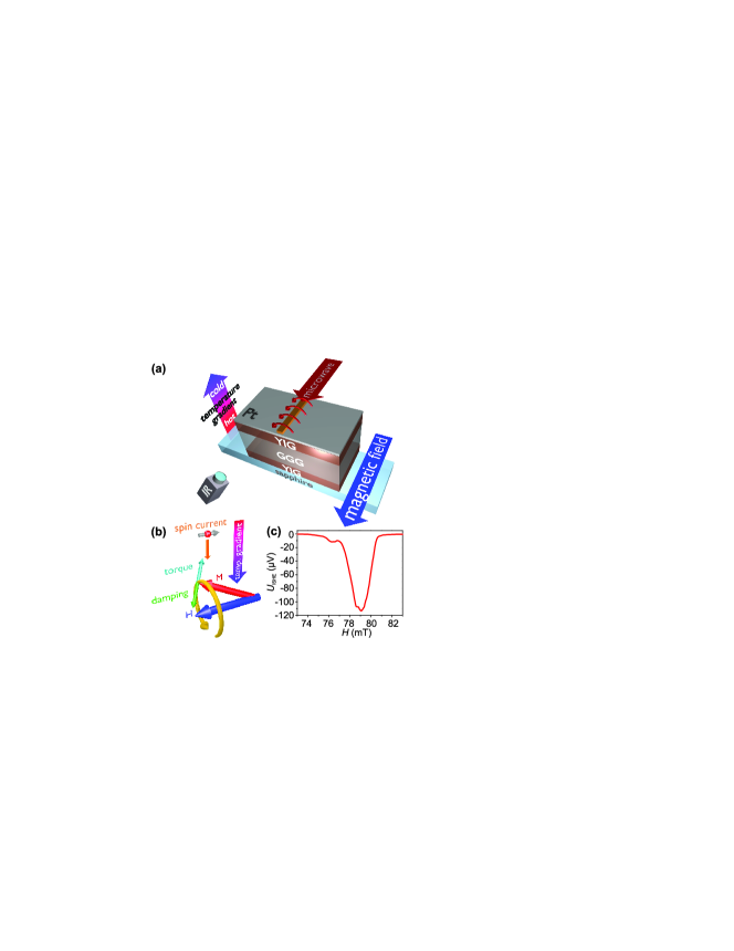
In this Letter, we report on the thermal manipulation of spin-wave relaxation measured by both microwave techniques as well as by spin pumping. The investigated sample consists of a YIG/GGG/YIG/Pt hetero-structure. A temperature difference applied across the thickness of this structure leads to the longitudinal SSE: an imbalance between the magnon and electron temperatures causes a spin current across the YIG/Pt interface. Uchida2010 ; Uchida_long The generated spin current transfers angular momentum and, consequently, they might exert a torque on the magnetization (see Fig. 1(b)). As a result, the magnetization precession can either be enhanced or suppressed depending on the sign of the temperature difference and, thus, the direction of the spin current. This change in the damping is equivalent to a variation of the ferromagnetic resonance linewidth that is measured by microwave reflection as well as by spin pumping.
A sketch of the experimental setup is shown in Fig. 1(a). A 2.1 m thick YIG film was grown by means of liquid phase epitaxy on both sides of a 500 m thick gadolinium gallium garnet (GGG) substrate. Using molecular beam epitaxy, we then deposited a Pt layer of 10 nm thickness on one side of the sample, fully covering one of the YIG surfaces. As shown in Ref. PRL_Chien_2012 the Pt layer might show ferromagnetic behavior on ferromagnetic insulators due to magnetic proximity effects. However, as shown in Ref. Kikkawa , a possible contamination by the anomalous Nernst effect is negligibly small compared to the longitudinal SSE contribution. A Peltier element, that is mounted on top of the Pt layer, generates a temperature difference across the multilayer. In order to enhance the temperature flow from the sample, the second YIG surface is covered with a sapphire substrate that is connected to a heat bath (sapphire is a good thermal conductor). The second YIG layer neither influences the magnetic nor the electric measurements but it should be noted that the temperature difference is applied across the entire Pt/YIG/GGG/YIG sample stack. The magnetization precession is excited by a 500 m wide copper microstrip antenna that is placed above the Pt layer with an intervening isolation layer (see Fig. 1(a)). The temperature difference is monitored using an infrared camera, calibrated by two thermocouples.
The experiment is performed as follows: an external magnetic field H is applied perpendicularly to the YIG waveguide in the YIG film plane. The magnetization precession is driven by the alternating magnetic field of a continuous microwave signal (see Fig. 1(a) and (b)) with a carrier frequency of 4 GHz and powers of dBm, +20 dBm, and +25 dBm. While sweeping the external magnetic field , a temperature difference across the sample thickness is applied and recorded by the infrared camera. The electric voltage due to the ISHE, , and the microwave reflection are measured simultaneously.
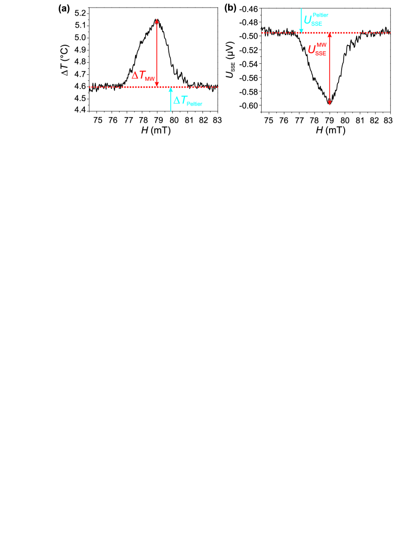
In the experiment, two different mechanisms contribute to the spin current: the spin Seebeck effect and the spin pumping effect. The SSE originates from the difference between the effective magnon temperature and the effective electron temperature at the YIG/Pt interface. Uchida_long ; Uchida2010 ; Uchida_JAP This temperature difference is created in two different ways in our experiment (see Fig. 2(a)): by the Peltier element (denoted by in the following) and by heating due to magnetization precession in resonance condition of the YIG film at (denoted by ). The second mechanism to create a spin current is spin pumping by the externally excited coherent magnetization precession. Tserkovnyak Irrespective of its origin, the net spin current injected into the Pt layer is transformed into a conventional charge current , perpendicular to both and H, by the ISHE (see Fig 1(c)). Hirsch ; Jungfleisch As a result, charges accumulate at the edges of the Pt layer and a voltage , composed of a spin pumping contribution and a SSE contribution , can be measured (Fig. 1(c)). The voltage itself consists of the voltage generated by heating due to magnetization precession in resonance and generated by the temperature difference . In order to distinguish between the different contributions to the following procedure has been used: for each temperature difference created with the Peltier element, and were recorded. From the off-resonance condition (), we can deduce a linear relation between and . Using this linear SSE relation Uchida_long ; Uchida2010 ; Uchida_JAP enables us to recalculate the corresponding voltage at and, thus, the spin pumping voltage , respectively. In Fig. 2 the evolution of the temperature difference as a function of the applied magnetic field and the corresponding SSE voltage are shown for a microwave power of dBm. Figure 2(a) clearly shows, that, in addition to the applied temperature difference of C, the temperature rises at by an additional value of C. The corresponding voltages and are illustrated in Fig. 2(b). For , the FMR driven spin pumping contribution is dominant ().
The heat-induced spin current affects our measurements in two different ways. On one side, it generates a voltage independent of the absolute value of the externally applied magnetic field H (crossing zero field results in a change of the polarity of according to the SSE Uchida_long ; Uchida2010 ; Uchida_JAP ), and on the other side, it most likely exerts a torque on the magnetization, resulting in the manipulation of the relaxation damping (see Fig. 1(b)).
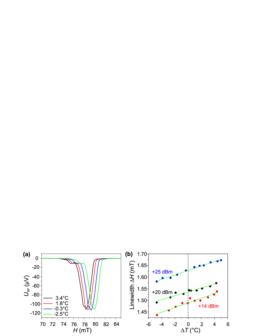
Figure 1(c) shows a typical example for the measured ISHE voltage without externally applied temperature difference. The voltage reaches its maximal absolute value at mT. In Fig. 3(a) the recalculated data is shown as a function of the external magnetic field for four different measured temperature differences . Heating and cooling the sample gives rise to a change of the saturation magnetization resulting in a resonance peak shift to higher or lower magnetic fields.
As it is obvious from Fig. 3(a), not only one but several modes contribute to the spin pumping voltage . Therefore, the envelope of is fitted for each temperature difference by a Gaussian function , where defines the linewidth which is a measure for the damping . The linewidth that is determined in this way, does not necessarily coincide with the real ferromagnetic resonance linewidth but is proportional to it, i. e. . The linewidth as a function of the temperature difference is shown in Fig. 3(b) for different microwave powers . It is clearly visible that the total linewidth decreases for one polarity of and increases for the other. We also analyzed each mode separately and we found that the qualitative behavior for each mode is the same.
As it is visible from Fig. 3(b), the variation of the linewidth per C temperature difference (slope in Fig. 3(b)) is approximately the same for all microwave powers. For a temperature difference of C, the linewidth changes about , independent of the microwave power. This independency is expected since the generated spin currents are thermally induced and, thus, do not depend on the applied microwave power. Uchida2010 The damping, i. e., the linewidth at is larger for higher microwave powers which is attributed to the onset of non-linear effects. Mills ; Hu ; Demidov_PRB
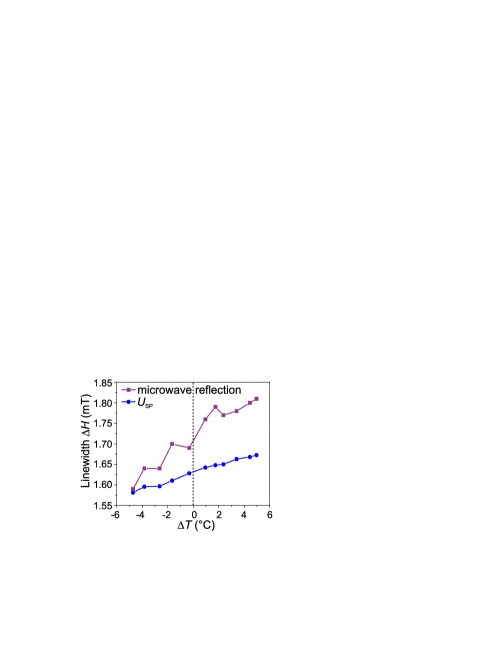
Now we compare how the linewidth alters under the influence of a longitudinal temperature difference measured by both spin pumping as well as microwave techniques. Since spin pumping is not sensitive to the spin-wave wavelength, the directly excited spin-wave modes as well as short-wavelength secondary waves contribute to the detected signal. Jungfleisch ; Chumak However, microwave reflection mainly detects the primary excited uniform mode. The results are summarized in Fig. 4. For both measurement techniques, the linewidth qualitatively behaves the same in the investigated range of temperature differences. Nevertheless, one can see that the slopes of the two curves diverge leading to the assumption that the uniform FMR mode is mostly effected by the heat-induced damping modification. However, a quantitative statement is not possible.
Assuming, that the observed heat-induced damping variation is due to thermal spin currents generated by the SSE, we calculate the variation of the magnetization relaxation in YIG/Pt hetero-structures based on the model developed in Ref. Ando_PRL_2008 . We modify this model by substituting a heat-induced spin current for a SHE-generated spin current: the charge current is replaced by the temperature difference . Thus, the generalized Landau-Lifshitz-Gilbert (LLG) equation is expressed as
| (1) |
where M is the magnetization, the gyromagnetic ratio, the effective magnetic field, the saturation magnetization, the volume of the YIG layer, and the spin polarization vector. The Gilbert damping is the sum of the intrinsic damping constant of the isolated YIG layer and is the additional damping due to spin pumping in the adjacent Pt layer. Tserkovnyak describes the heat-induced spin torque. By introducing the injection and charge current conversion efficiency , where is the slope obtained by fitting our results (Fig. 3(b)), and by introducing an additional temperature dependent damping parameter , we obtain, in analogy to Ref. Ando_PRL_2008 , the heat-induced spin torque
| (2) |
The spin-current density is given by .
| (dBm) | ||
|---|---|---|
| +14 | 1.74 0.15 | 3.70 0.32 |
| +20 | 2.11 0.18 | 4.49 0.39 |
| +25 | 2.01 0.08 | 4.27 0.16 |
The calculated spin torque and the spin current density are summarized for different microwave powers in Table 1. For these calculations is assumed to be constant since leads to variations of only about which cannot explain the observed behavior. It should be emphasized that our calculated heat-induced spin current density per 1 is one to two orders of magnitude higher than those generated by the SHE for the maximal DC voltage pulses used in Ref. MWu2011 of V (, Pt resistance , DC pulse length 300 ns, repetition rate 10 ms).
Taking the large magnitude of the observed heat-induced STT (linewidth change about 6) for the comparably small temperature difference across the actual YIG/Pt interface (less than 0.1∘C) into account, we might consider influences on by other effects: (1) The change in electric resistance of the Pt layer due to the applied temperature difference (less than approximately ) cannot be the origin of the observed linewidth change. (2) In the present experiment, phonons penetrating the entire sample stack (including the 500 m thick GGG layer) are the main heat carriers. Uchida_long ; Uchida_JAP Consequently, they are the major cause for the thermally-induced spin current.
In conclusion, the heat-induced damping modification in YIG/Pt hetero-structures has been shown. The modulation of the relaxation coefficient has been demonstrated by spin pumping as well as by microwave techniques. Both techniques qualitatively show the same behavior. Besides that, our findings demonstrate, that every spin pumping experiment, in which the coherent magnetization precession is driven by a microwave source, is accompanied by heating. We have introduced a method to identify spin pumping from coherent magnons and SSE contribution from incoherent magnons to the ISHE voltage, resulting in an increase of the ISHE voltage of around 0.1%. The spin transfer due to the temperature difference across the YIG/Pt interface has been estimated and has been compared to previous works that use SHE-generated spin currents. It turns out, that the heat-induced spin current density per 1 is of the order .
We thank G. A. Melkov for valuable discussions and R. Neb for the platinum film deposition. Financial support by the Deutsche Forschungsgemeinschaft within the projects SE 1771/4-1 (Priority Program 1538 Spin Caloric Transport ) and CH 1037/1-1 is gratefully acknowledged.
References
- (1) E. Saitoh, M. Ueda, H. Miyajima, and G. Tatara, Appl. Phys. Lett. 88, 182509 (2006).
- (2) C. W. Sandweg, Y. Kajiwara, A. V. Chumak, A. A. Serga, V. I. Vasyuchka, M. B. Jungfleisch, E. Saitoh, and B. Hillebrands, Phys. Rev. Lett. 106, 216601 (2011).
- (3) K. Uchida, J. Xiao, H. Adachi, J. Ohe, S. Takahashi, J. Ieda, T. Ota, Y. Kajiwara, H. Umezawa, H. Kawai, G. E. W. Bauer, S. Maekawa, and E. Saitoh, Nature Mater. 9, 894 (2010).
- (4) K. Uchida, H. Adachi, T. Ota, H. Nakayama, S. Maekawa, and E. Saitoh, Appl. Phys. Lett. 97, 172505 (2010).
- (5) A. G. Gurevich and G. A. Melkov, Magnetization Oscillations and Waves (CRC, New York, 1996).
- (6) Z. Wang, Y. Sun, M. Wu, V. Tiberkevich, and A. N. Slavin, Phys. Rev. Lett. 107, 146602 (2011).
- (7) E. Padrón-Hernández, A. Azevedo, and S. M.Rezende, Phys. Rev. Lett. 107, 197203 (2011).
- (8) K. Ando, S. Takahashi, K. Harii, K. Sasage, J. Ieda, S. Maekawa, and E. Saitoh, Phys. Rev. Lett. 101, 036601 (2011).
- (9) L. Lu, Y. Sun, M. Jantz, and M. Wu, Phys. Rev. Lett. 108, 257202 (2012).
- (10) M. B. Jungfleisch, A. V. Chumak, V. I. Vasyuchka, A. A. Serga, B. Obry, H. Schultheiss, P. A. Beck, A. D. Karenowska, E. Saitoh, and B. Hillebrands Appl. Phys. Lett. 99, 182512 (2011).
- (11) A. V. Chumak, A. A. Serga, M. B. Jungfleisch, R. Neb, D. A. Bozhko, V. S. Tiberkevich, and B. Hillebrands, Appl. Phys. Lett. 100, 082405 (2012).
- (12) Y. Tserkovnyak, A. Brataas, and G. E. W. Bauer, Phys. Rev. Lett. 88, 117601 (2002).
- (13) M. V. Costache, M. Sladkov, S. M. Watts, C. H. van der Waal, and B. J. van Wees, Phys. Rev. Lett. 97, 216603 (2006).
- (14) S. Y. Huang, X. Fan, D. Qu, Y. P. Chen, W. G. Wang, J. Wu, T. Y. Chen, J. Q. Xiao, and C. L. Chien, Phys. Rev. Lett. 109, 107204 (2012).
- (15) T. Kikkawa, K. Uchida, Y. Shiomi, Z. Qiu, D. Hou, D. Tian, H. Nakayama, X.-F. Jin, E. Saitoh, arXiv:1211.0139 [cond-mat.mtrl-sci].
- (16) K. Uchida, T. Ota, H. Adachi, J. Xiao, T. Nonaka, Y. Kajiwara, G. E. W. Bauer, S. Maekawa, and E. Saitoh, J. Appl. Phys. 111, 103903 (2012).
- (17) J. E. Hirsch, Phys. Rev. Lett. 83, 1834 (1999).
- (18) Y. Khivintsev, Bijoy Kuanr, T. J. Fal, M. Haftel, R. E. Camley, Z. Celinski, and D. L. Mills, Phys. Rev. B 81, 054436 (2010).
- (19) Y. S. Gui, A. Wirthmann, and C.-M. Hu, Phys. Rev. B 80, 184422 (2009).
- (20) V. E. Demidov, H. Ulrichs, S. O. Demokritov, and S. Urazhdin, Phys. Rev. B 83, 020404(R) (2011).
- (21) L. D. Landau and E. M. Lifshitz, Physikalische Zeitschrift der Sowjetunion 8, 153 (1935).
- (22) T. Valet and A. Fert, Phys. Rev. B 48, 7099 (1993).
- (23) S. Takahashi and S. Maekawa, J. Magn. Magn. Mater. 310, 2067 (2007).