A compact single-chamber apparatus for Bose-Einstein condensation of 87Rb
Abstract
We describe a simple and compact single-chamber apparatus for robust production of Bose-Einstein condensates. The apparatus is built from off-the-shelf components and allows production of quasi-pure condensates of atoms in s. This is achieved using a hybrid trap created by a quadrupole magnetic field and a single red-detuned laser beam [Y.-J. Lin et al., Phys. Rev. A 79, 063631 (2009)]. In the same apparatus we also achieve condensation in an optically plugged quadrupole trap [K. B. Davis et al., Phys. Rev. Lett. 75, 3969 (1995)]; we show that as little as mW of plug-laser power is sufficient for condensation, making it viable to pursue this approach using inexpensive diode lasers. While very compact, our apparatus features sufficient optical access for complex experiments, and we have recently used it to demonstrate condensation in a uniform optical-box potential [A. Gaunt et al., arXiv:1212.4453 (2012)].
pacs:
67.85.-d, 37.10.DeI Introduction
Atomic Bose-Einstein condensates (BECs) are now widely used for studies of many-body physics Bloch:2008 and as bright sources for atom optics and interferometry Cronin:2009 . Since the first demonstrations of condensation in magnetic Anderson1995 ; Bradley1995 ; Davis1995 and optical Barrett2001 traps, the development of experimental setups for BEC production has generally taken two parallel routes. On one hand, some applications require ever more complex setups; these, for example, include multi-species experiments Tablieber:2008 , single-particle detection Bakr:2009 or hybrid systems combining neutral atoms and ions Zipkes:2010 . On the other hand, there has also been a continuing effort to design simple and inexpensive machines that are still suitable for many experiments Lewandowski2003 ; Du2004 ; Naik2005 ; Heo2011 ; Weber2003 ; Kinoshita2005 ; Jacob2011 ; Arnold2011a .
In this paper, we describe a particularly simple apparatus, built exclusively from off-the-shelf components, and our cooling procedure for production of BECs. While being compact and consisting of a single vacuum chamber for both laser and evaporative cooling (see Fig. 1), our setup features BEC atom numbers and production rates comparable to most multi-chamber setups, as well as sufficient optical access for complex experiments. By evaporative cooling in a hybrid magnetic-optical trap introduced by Lin et al. Lin2009 , we reliably produce quasi-pure BECs of atoms in s. Using the same setup, we also explored condensation in an optically plugged quadrupole trap Davis1995 . Specifically, we study the plugging laser power requirements for a range of plug-laser wavelengths and show that it is possible to achieve condensation using as little as mW of plug power. This opens the possibility of implementing this approach using inexpensive diode lasers. Recently, we have used this apparatus (in the hybrid-trap configuration) to demonstrate Bose-Einstein condensation in a uniform optical-box potential Gaunt:2013 . This unambiguously shows that this simple and inexpensive setup is sufficient for many non-trivial experiments requiring significant optical access to the atomic cloud.
The article is structured as follows. In Sec. II we outline our experimental setup. In Sec. III we provide details of the laser cooling stage of our experiments. Evaporative cooling and condensation in a hybrid trap are described in Sec. IV, while experiments with an optically plugged trap are discussed in Sec. V. Finally, in Sec. VI we summarise our results.
II Experimental Setup
II.1 Vacuum System
BEC production in a single-chamber vacuum system is subject to two contradicting requirements: while a higher vapour pressure facilitates loading of the magneto-optical trap (MOT), a lower background gas pressure increases the lifetime and evaporation efficiency during later cooling stages. Condensation is achieved by carefully balancing these two requirements. In our experiments this balance is improved by using isotopically pure vapour sources (purchased from Alvatec).
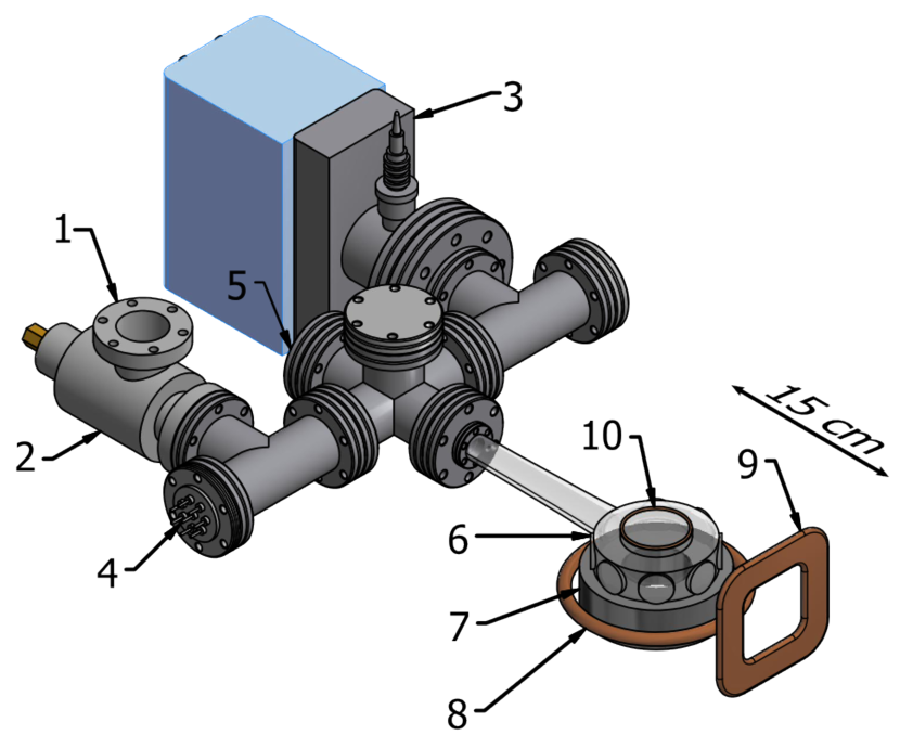
Our vacuum system is shown in Fig. 1. A quartz cell by Triad Technology allows optical access via two (top and bottom) and eight anti-reflection coated windows. The vacuum is maintained by a single ion pump. After moderate baking of the system, at for a week, we achieve magnetic trap lifetimes of over . The pressure typically reduces this to about .
II.2 Magnetic Coils
The magnetic quadrupole field for both the MOT and the magnetic trap is created by an anti-Helmholtz pair of 16-turn water-cooled coils wound from 4 mm copper tubing (“7” in Fig. 1). These create an axial gradient of when carrying .
The quantisation axis for optical pumping and imaging is provided by a magnetic field along the imaging axis. We use a low-inductance planar 10 turn coil wound from copper wire (“9” in Fig. 1), providing a field of at the atoms.
Gravity compensation during time-of-flight (TOF) measurements is achieved by combining a quadrupole field (created by the MOT coils) with a homogeneous vertical bias field. Residual potential curvature is minimised by a high bias field strength. We use two 50-turn coils in a Helmholtz configuration (“8” in Fig. 1), providing a bias field of when run at 10 A.
A radio-frequency (RF) field for forced evaporative cooling is created by a three-turn coil mounted against the top viewport of the cell. For transitions between neighbouring states separated by up to , we achieve Rabi frequencies above using of RF power.
II.3 Laser-Cooling System
Magneto-optical trapping of requires two laser frequencies of its line (near . We use two grating-stabilised external-cavity diode lasers (DL Pro from Toptica Photonics). They are referenced to separate vapor cells to generate cooling light close to the cycling transition and repumping light resonant with the transition. Cooling light is amplified using a tapered amplifier (BoosTA from Toptica). The cooling and repumping light pass through acousto-optic modulators (AOMs) and are combined in a two- to six-way free-space fiber port cluster, built in-house from OFR components (distributed by Thorlabs).
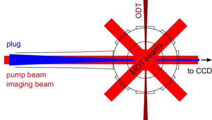
The spatial arrangement of our laser beams is shown in Fig. 2. The six MOT beams are delivered to the glass cell via optical fibers. A total of of cooling light and of repumping light reaches the atoms. We use large diameter () beams which do not need to be realigned for months. The light for optical pumping and absorption imaging of the atoms is derived from the cooling light. The pumping and imaging beams are controlled by additional AOMs and enter the chamber via the “back” viewport (5 in Fig. 1).
II.4 Single-Beam Dipole Trap
The optical-dipole-trap (ODT) beam used for the hybrid trap is derived from a ytterbium fiber laser (YLR-20-LP from IPG Photonics). After passing through an AOM, the beam is focused by a concave-convex pair of lenses, allowing the adjustment of both waist size and position. We typically use a beam waist of and a maximum power of at the atoms. Higher powers lead to excessive atom losses, which can be attributed to two-photon transitions Lauber2011b ; these transitions are caused by the large linewidth of the trapping laser ( in our case). The focal point is positioned approximately a beam waist below the zero of the magnetic quadrupole field. The beam power is controlled in the range using a feedback loop consisting of a photodiode, a proportional-integral-derivative (PID) controller, and the AOM. Throughout this range, we achieve an rms power noise below over a bandwidth of .
II.5 Optical-Plug Beam
In our experiments, for the optical-plug light we used a Ti:Sapphire laser (Coherent MBR-110) in order to explore a range of plug wavelengths and powers. However, since we show that as little as of plug power is sufficient to achieve quantum degeneracy, in future experiments the plug light could be generated using a simple diode laser.
The plug beam is focused to a waist of and aligned to overlap with the zero of the magnetic quadrupole field, as shown in Fig. 2.
II.6 Imaging
We image the atoms with a collimated, circularly polarised beam, resonant with the transition. The imaging efficiency was calibrated to account for the deviations of the absorption cross-section from the theoretical value, primarily due to imperfections in the polarisation of the imaging light. We compared the measured atom number at the BEC critical point with the theoretically predicted critical number . was measured by extrapolating the non-saturation slope of the thermal component to the condensation point as described in Tammuz2011 ; Smith2011 . We found an imaging efficiency of , which lies in the range typical of other experiments Gerbier2004 ; Sanner2010 .
III Laser Cooling
For the MOT we use an axial field gradient of and a cooling-light detuning of . Typically, we load the MOT to atoms in . Note, however, that s of loading are sufficient to produce BECs with atoms. In daily operation, MOT atom numbers are deduced from the intensity of fluorescence light collected on a photodiode, which was calibrated using absorption imaging.
Following the initial loading stage, we compress the MOT by increasing to for , and then detune the cooling light to for (CMOT, Petrich1994 ). We found that these steps reduce the temperature and improve transfer into the magnetic trap. These steps are followed by of optical molasses during which the magnetic field is switched off and the cooling-light detuning of is maintained. This cools the cloud to .
IV Condensation in a Hybrid Trap
Following molasses, the atoms are optically pumped into the hyperfine ground state, using a combination of resonant light and repump light. We pump of the atoms into the state in , while heating the cloud to .
The atoms are then captured in a magnetic potential by suddenly turning on the quadrupole field with (matching the gradient of the CMOT) and then ramping to over . Finally, the trap is further compressed by raising to over .
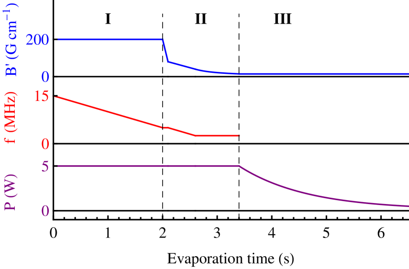
From this point on, the evaporative cooling to condensation can be divided into three stages: (I) RF evaporation, (II) transfer into the hybrid trap, and (III) ODT evaporation.
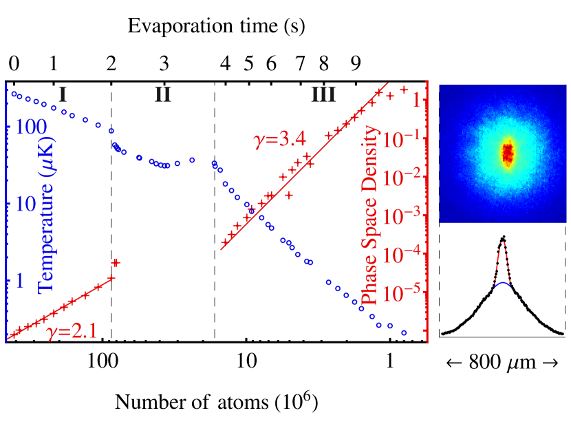
Fig. 3 summarises the evolution of the relevant experimental parameters during the evaporation sequence, while Fig. 4 displays the evolution of the atom number , the temperature , and the calculated phase-space density .
and are measured using time-of-flight (TOF) absorption imaging and is calculated from a semiclassical model Lin2009 , using an analytical expression for the hybrid trapping potential. We verified the parameters of the model (such as beam waist) by measuring trapping frequencies and comparing them with theoretical predictions. We omit the calculated values of in stage II, where they are unreliable because the trapping potential varies slowly over large volumes.
IV.1 RF Evaporation
During the initial evaporation stage in the compressed trap (I in Figs. 3 and 4), we ramp the RF frequency linearly from to in . We achieve a 30-fold increase in the peak phase space density, with an evaporation efficiency .
At the end of this stage the cloud typically contains atoms at .
IV.2 Loading of the Hybrid Trap
In stage II the magnetic field gradient is decompressed to just below the gravity-compensating value, , where is the atom mass, is the gravitational acceleration and is the Bohr magneton. From this point on, the atoms are supported against gravity by optical forces only, while the confinement along the ODT axis is dominated by the magnetic forces Lin2009 . Note that the ODT beam is on from the beginning of the magnetic trapping (see Fig. 3), but initially does not have a dominant role.
We decompress to over while keeping the RF frequency constant, then decompress further to while sweeping the RF frequency linearly to in ; this provides a good gain in phase-space density despite the weak magnetic confinement. Finally, the magnetic field is decompressed from to . In this step we sweep the field gradient according to , where and the sweep duration is . This changes the RF-limited trap depth approximately linearly with time, with the approximation being exact in the case of no ODT and .
At the end of this stage we typically have atoms at .
IV.3 Optical Evaporation
For , evaporation is no longer driven by the RF field. Instead, the trap depth is limited by the potential height at a saddle point vertically below the magnetic-field zero Hung2008a . Evaporation can thus be forced efficiently by lowering the ODT power, , albeit at the cost of a small reduction in the trapping frequencies.
We ramp exponentially to its final value, , with a time constant of and total ramp duration of . (Both parameters have been optimised empirically.) We achieve an evaporation efficiency of , leading to condensation at .
At the critical point, and . At this point, the trapping frequency is about 30 Hz along the ODT axis and about 90 Hz radially.
Lowering the ODT power further results in quasi-pure condensates of atoms. The lifetime of the quasi-pure BEC is , consistent with the expected 3-body losses Burt1997 .
V Condensation in a Plugged Quadrupole Trap
Our experiments with the optically plugged quadrupole trap were performed before we could introduce the isotopically pure vapour sources into the setup. For this reason the atom numbers in the hybrid and plugged traps cannot be directly compared. The abundance of in the natural isotopic mixture means that for the same background pressure, hence the same MOT loading time and cloud lifetime in the magnetic trap, the MOT loading rate is about 4 times smaller. The collisional rate, which determines the efficiency of evaporative cooling, is then also correspondingly lower. As a result of these effects, we could produce only smaller BECs, containing up to atoms.
Our goal here, however, was not to maximise the atom number, but to investigate the minimal requirements on the plug-laser power. The improvements brought about by using isotopically pure sources should equally increase the degenerate sample size in plugged-trap experiments.
In the first plugged-trap experiment, W of 532 nm laser power was used Davis1995 , while later it was shown that by reducing the plug size this requirement can be reduced to W Naik2005 . Here we show that bringing the laser wavelength closer to the atomic resonance can reduce this value to as little as mW.
V.1 Cooling Sequence
In these experiments, the laser-cooling stage was essentially the same as in Sec. III, except that the optimisation of the rubidium pressure for best BEC production resulted in atoms being loaded into the MOT.
The atoms were then loaded into the plugged quadrupole trap with an axial gradient of . The strong magnetic confinement compensates for the smaller initial atom number and allows the initiation of evaporative cooling. RF evaporation started at . After holding constant for , we swept it linearly to in . At this point the cloud was sufficiently dense for the losses due to three-body recombination to become relevant Dubessy:2012 . We thus decompressed the trap to in . The RF frequency was then swept exponentially from to in .
V.2 Effects of Plug Power and Wavelength
| (a) |
 |
| (b) |
 |
In the above cooling sequence, the plug laser beam was on from the moment the atoms were loaded into the quadrupole magnetic trap. However, its efficiency in preventing Majorana losses depends on its power and wavelength. Reducing the beam detuning from the atomic resonance increases both the optical dipole forces and the spontaneous light scattering, thus allowing smaller powers to be used, but at the cost of more heating and shorter lifetimes.
To study this effect quantitatively, we varied the plug-laser wavelength in the range and the beam power, , in the range mW - , while keeping the beam geometry fixed.
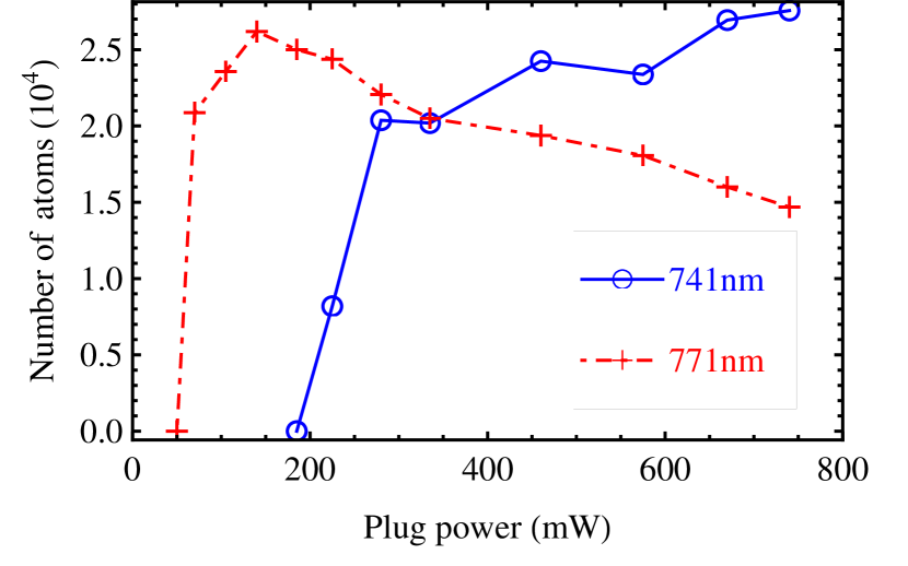
Fig. 5(a) shows the number of atoms in the condensed cloud as a function of for two different wavelengths. At nm we achieve condensation for mW; increasing beyond 300 mW leads to only a slow increase in the atom number. At nm, as little as 70 mW of plug power is sufficient for condensation. Note, however, that in this case one should use the minimum necessary laser power, since increasing further actually has adverse effects due to the increased spontaneous light scattering.
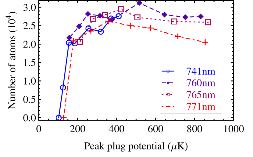
In Fig. 5(b) we plot the number of atoms at the end of the evaporation versus the peak value of the repulsive potential created by the plug beam. We see that the threshold potential is in fact the same for a range of wavelengths. This also shows that (for this range of wavelengths) the spontaneous light scattering is not relevant for powers up to the threshold value. Only for higher peak potentials we see that longer wavelengths (closer to resonance) lead to lower atom numbers due to the spontaneous scattering.
VI Conclusion
We have described a simple single-chamber apparatus for producing Bose-Einstein condensates of by evaporative cooling in either a hybrid magnetic-optical trap or an optically plugged quadrupole trap. With the hybrid-trap approach we achieve BECs with atoms, comparable to most multi-chamber setups. In our experiments with the optically plugged trap the main result is that as little as 70 mW of plug power is sufficient to achieve condensation. This makes it possible to pursue this approach using inexpensive diode lasers.
We hope that our description of both experimental approaches will benefit groups wanting to design simple and cost-efficient BEC machines for various applications.
Acknowledgements.
This work was supported by EPSRC (Grant No. EP/G026823/1), the Royal Society and a grant from the Army Research Office with funding from the DARPA OLE program.References
- (1) I. Bloch, J. Dalibard, and W. Zwerger, Rev. Mod. Phys. 80, 885 (2008).
- (2) A. D. Cronin, J. Schmiedmayer, and D. E. Pritchard, Rev. Mod. Phys. 81, 1051 (2009).
- (3) M. H. Anderson et al., Science 269, 198 (1995).
- (4) C. C. Bradley, C. A. Sackett, J. J. Tollett, and R. G. Hulet, Phys. Rev. Lett. 75, 1687 (1995).
- (5) K. B. Davis et al., Phys. Rev. Lett. 75, 3969 (1995).
- (6) M. D. Barrett, J. A. Sauer, and M. S. Chapman, Phys. Rev. Lett. 87, 010404 (2001).
- (7) M. Taglieber et al., Phys. Rev. Lett. 100, 010401 (2008).
- (8) W. S. Bakr, A. Peng, S. Folling, and M. Greiner, Nature 462, 74 (2009).
- (9) C. Zipkes, S. Palzer, C. Sias, and M. Köhl, Nature 464, 388 (2010).
- (10) H. J. Lewandowski, D. M. Harber, D. L. Whitaker, and E. A. Cornell, J. Low Temp. Phys. 132, 309 (2003).
- (11) S. Du et al., Phys. Rev. A 70, 053606 (2004).
- (12) D. S. Naik and C. Raman, Phys. Rev. A 71, 033617 (2005).
- (13) M.-S. Heo, J.-Y. Choi, and Y.-I. Shin, Phys. Rev. A 83, 013622 (2011).
- (14) T. Weber et al., Science 299, 232 (2003).
- (15) T. Kinoshita, T. Wenger, and D. S. Weiss, Phys. Rev. A 71, 011602 (2005).
- (16) D. Jacob et al., New J. Phys. 13, 065022 (2011).
- (17) K. Arnold and M. Barrett, Opt. Commun. 284, 3288 (2011).
- (18) Y.-J. Lin et al., Phys. Rev. A 79, 063631 (2009).
- (19) A. Gaunt et al., arXiv:1212.4453 (2012).
- (20) T. Lauber, J. Küber, O. Wille, and G. Birkl, Phys. Rev. A 84, 043641 (2011).
- (21) N. Tammuz et al., Phys. Rev. Lett. 106, 230401 (2011).
- (22) R. P. Smith, R. L. D. Campbell, N. Tammuz, and Z. Hadzibabic, Phys. Rev. Lett. 106, 250403 (2011).
- (23) F. Gerbier et al., Phys. Rev. Lett. 92, 030405 (2004).
- (24) C. Sanner et al., Phys. Rev. Lett. 105, 040402 (2010).
- (25) W. Petrich, M. H. Anderson, J. R. Ensher, and E. A. Cornell, J. Opt. Soc. Am. B 11, 1332 (1994).
- (26) C.-L. Hung, X. Zhang, N. Gemelke, and C. Chin, Phys. Rev. A 78, 011604 (2008).
- (27) E. A. Burt et al., Phys. Rev. Lett. 79, 337 (1997).
- (28) R. Dubessy et al., Phys. Rev. A 85, 013643 (2012).