Implementation of an impedance-matched system by dressed-state engineering
Abstract
In one-dimensional optical setups, light-matter interaction is drastically enhanced by the interference between the incident and scattered fields. Particularly, in the impedance-matched -type three-level systems, a single photon deterministically induces the Raman transition and switches the electronic state of the system. Here we show that such a system can be implemented by using dressed states of a driven superconducting qubit and a resonator. The input microwave photons are perfectly absorbed and are down-converted into other frequency modes in the same waveguide. The proposed setup is applicable to single-photon detection in the microwave domain.
pacs:
03.67.Lx, 85.25.Cp, 42.50.PqIn one-dimensional optical setups, radiation from a quantum emitter is guided completely to specified one-dimensional propagating modes. We can realize such setups in a variety of physical systems, such as optical cavity quantum electrodynamics (QED) systems using atoms or quantum dots oned1 ; oned2 ; oned3 and circuit QED systems using superconducting qubits oned4 ; oned5 ; oned6 . When we apply a field to excite the emitter through the one-dimensional mode in these setups, the incident field inevitably interferes with the field scattered by the emitter due to the low dimensionality io1 . As a result, we can realize unique optical phenomena that are not achievable in three-dimensional free space. A classical example is the complete transmission of a resonant field through a two-sided cavity, in which reflection from the cavity is forbidden due to the destructive interference between the incident field and the cavity emission in the reflection direction. Such one-dimensional optical setups in which reflection from the emitter is forbidden are called impedance-matched, in analogy with properly terminated electric circuits imp1 ; imp2 . Recently, perfect reflection of the incident field by a single emitter has been confirmed in both optical cavity QED and circuit QED systems oned2 ; oned5 . Here, transmission is forbidden by the destructive interference occurring in the transmission direction.
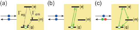
In this study, we investigate a three-level system interacting with a semi-infinite one-dimensional field in a reflection geometry (Fig. 1). We denote the three levels of the system by , and from the lowest. We assume that decays to with a finite lifetime and therefore that the system is in when stationary. When a single photon resonant to the transition is input, there are three possible processes: (a) simple reflection without exciting the system, (b) elastic scattering, inducing the transitions, and (c) inelastic scattering, inducing the transitions. Destructive interference occurs here between processes (a) and (b). In particular, they cancel each other completely when the two decay rates from the top level are identical () and the coherence length of the input photon is sufficiently long. As a result, the input photon is down-converted deterministically, inducing the Raman transition in the system [Fig. 1(c)] dc . This is the impedance-matching in the system. The charm of such impedance-matched systems is the deterministic electronic dynamics induced by single photons, which enables novel quantum technologies. Based on such systems, single-photon transistors, quantum memories, and optical quantum gates have been theoretically proposed Lam1 ; Lam2 ; Lam3 ; Lam4 ; Lam5 ; Lam6 .
In superconducting qubits, we use several discrete levels formed at the bottom of the anharmonic potential as an artificial atom. We usually make the potential symmetric in order to suppress dephasing. Then, each eigenstate has a definite parity and the qubit functions as a ladder-type multilevel system. We can also make the potential asymmetric, for example by introducing flux bias in flux qubits. The lowest three levels then function as a system, which have been used to demonstrate, for example, lasing and cooling of qubits las2 ; las3 ; las4 . However, it is difficult to satisfy the impedance-matching condition, i.e., identical decay rates from the second excited state, in the systems thus created.
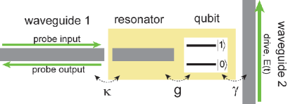
In this study, we propose a practical scheme for implementing an impedance-matched system by using dressed states of a qubit and a resonator. The schematic of the considered setup is shown in Fig. 2. A superconducting qubit is coupled to a resonator, which is further coupled to a semi-infinite waveguide (waveguide 1). Through another waveguide (waveguide 2), a drive field is applied to the qubit. The qubit functions as a two-level system ( and ). Setting , where is the microwave velocity in the waveguides, the Hamiltonian of the system is
| (1) | |||||
| (2) | |||||
| (3) |
The meanings of the operators are as follows: and are the annihilation operators of the qubit and the resonator, respectively, and () is the photon annihilation operator in waveguide 1 (2) with wave number . The meanings of the parameters are as follows: and are the resonance frequencies of the qubit and resonator, respectively, is the qubit-resonator coupling, and () is the decay rate of the resonator (qubit) into waveguide 1 (2). For simplicity, is assumed to include the nonradiative decay of the qubit. We consider the case in which the qubit and the resonator are highly detuned () and are coupled dispersively. The drive field is monochromatic, , and is close to the resonance of the qubit. We employ the following parameters: GHz, GHz, MHz, MHz, and MHz.
By switching to the frame rotating at the drive frequency , the Hamiltonian becomes static. Then, . remains unchanged except that the photon frequency is measured from . We define the dressed states of the qubit and the resonator by the eigenstates of . We denote them by and their energies by () from the lowest. In the dressed-state basis, the Hamiltonian is rewritten as
| (4) | |||||
| (5) | |||||
| (6) |
where and () is the radiative decay rate into waveguide 1 (2) for transition. and are respectively given by
| (7) | |||||
| (8) |
Thus, the time-dependent Hamiltonian in the bare-state basis [Eq. (1)] is transformed into a static one in the dressed-state basis [Eq. (4)].
For , the eigenstates of are simply the product Fock states of the qubit and the resonator, ( and ). The qubit-resonator coupling mixes these states only slightly due to the large detuning and brings about dispersive level shifts. Within the second-order perturbation, the eigenenergies are given by
| (9) | |||||
| (10) |
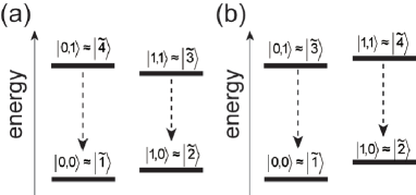
where . In this study, we investigate the case in which a weak probe field is input from waveguide 1. Therefore, only the four lowest levels (, , , and ) are relevant. Their energy diagrams are shown in Fig. 3 for . Due to the dispersive level shifts, with the proper choice of the drive frequency (), the level structure becomes nested, i.e., [Fig. 3(a)]. When is out of this range, the level structure becomes unnested [Fig. 3(b)]. We refer to the former (latter) case as the nesting (unnesting) regime hereafter.
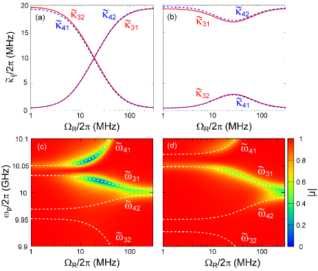
Next, we discuss the effects of driving. The drive field mixes the lower (higher) two levels in Fig. 3 to form dressed states and ( and ). Therefore, neglecting the slight mixing originating in the dispersive coupling, dressed states are roughly written as , , , and , where and depend on the frequency and the power of the drive field. From Eq. (7), the radiative decay rates into waveguide 1 are given by , , and others vanish. For weak drive, and accordingly in the nesting regime [Fig. 3(a)], whereas and accordingly in the unnesting regime [Fig. 3(b)]. In contrast, for strong drive, where the Rabi splittings overwhelm the dispersive level shifts, and therefore in both nesting and unnesting regimes. In Fig. 4(a) and (b), , , and are evaluated rigorously from Eq. (7), using the Rabi frequency, , as a measure of the drive power. We observe that and at any drive power in accordance with the above discussion. Remarkably, inversion of these decay rates occurs in the nesting regime [Fig. 4(a)], and the two radiative decay rates from or become identical with the proper choice of the drive power ( MHz). At this drive power, the qubit-resonator system functions as an impedance-matched system, with , , and or . It is numerically confirmed that the lower two levels are mixed only slightly; (qubit ground state) and (qubit excited state). Therefore, the decay rate is of the qubit origin and , while and are of the cavity origin and .
In the following, we analyze the microwave response of this qubit-resonator system to a probe field applied through waveguide 1. From the Hamiltonian of Eq. (4), the Heisenberg equation for is
| (11) |
where (), , and . The input and output field operators, and , are connected by
| (12) |
We assume that a monochromatic probe field with amplitude and frequency is applied from waveguide 1, while no probe field is applied from waveguide 2, i.e., and . Note that the probe frequency is measured from the drive frequency since we are working in the rotating frame.
We define the reflection coefficient by the ratio of output and input amplitudes, i.e., . For weak probe, the system exhibits linear response and therefore is independent of the probe power. In Fig. 4(c) and (d), is plotted as a function of the drive power and the probe frequency, together with the relevant transition frequencies between dressed states. Since dissipation (decay into waveguide 2) is negligible here, the attenuation of results from the inelastic scattering. We observe in Fig. 4(c) that strong suppression of the reflected field amplitude takes place in the nesting regime as a result of the impedance matching. The conditions are that (i) the decay rates from () to and are identical [ MHz in Fig. 4(a)], and that (ii) the probe frequency is tuned to (). Since level is almost unoccupied for a weak probe power, no specific signal appears at or . We observe in Fig. 4(d) that impedance matching never occurs in the unnesting regime.
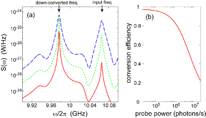
Although the probe amplitude vanishes, this does not imply dissipation of the probe power. Figure 5(a) plots the power spectrum of the output field, , under the impedance-matching condition. The input probe is tuned to ( GHz). However, upon the interaction with the qubit and the resonator, the probe field is down-converted nearly completely and forms a dominant peak at ( GHz). Figure 5(b) plots the down-conversion efficiency, which is defined by the area of the down-converted peak normalized by the input power, . We observe that, at low probe power, most input photons are down-converted. The conversion efficiency is slightly less than unity even in the weak-probe limit. This is due to the qubit-origin decay of level into waveguide 2. The conversion efficiency decreases as the probe power increases. This is due to saturation of the system: The bottleneck process here is the decay, the rate of which is approximately . Therefore, when the input flux exceeds ( photons/s), is populated gradually and the system becomes insensitive to the probe.
Two final comments are in order. (i) For impedance matching, achieving the nested energy diagram [Fig. 3(a)] is essential and therefore a large dispersive shift is advantageous Forn . In this regard, the systems in the so-called straddling regime are promising, in which the dispersive shift is enhanced by the presence of the second excited state of the qubit Ino ; stra1 . Numerical results are qualitatively unchanged if we extend the model in this direction. (ii) When a resonant photon with pulse length is input from waveguide 1, it induces the transition nearly deterministically provided that dc . As discussed, and respectively correspond to the qubit’s ground and excited states. Namely, a single photon deterministically excites the qubit. Therefore, by performing the dispersive quantum-nondemolition readout of the qubit read2 ; read3 within a relatively long qubit lifetime (), we can apply this setup to the detection of single microwave photons det1 ; det2 ; det3 . A large dispersive shift is advantageous also in this regard.
In summary, we proposed a circuit-QED implementation of an impedance-matched system. We considered a setup composed of a driven superconducting qubit, a resonator and a waveguide. The lowest four dressed states of the qubit-resonator system, , , , and , are relevant in this study. With the proper choice of the drive frequency and intensity, two radiative decay rates from or become identical; the system then functions as an impedance-matched system, where , and or . When a probe field tuned to the transition is applied from the waveguide, the probe field loses its coherent amplitude and is down-converted nearly completely. The present setup is applicable to the detection of single microwave photons.
This work was partly supported by the Funding Program for World-Leading Innovative R&D on Science and Technology (FIRST), Project for Developing Innovation Systems of MEXT, MEXT KAKENHI (Grant Nos. 21102002, 25400417), SCOPE (111507004), and National Institute of Information and Communications Technology (NICT).
References
- (1) Q. A. Turchette, C. J. Hood, W. Lange, H. Mabuchi, and H. J. Kimble, Phys. Rev. Lett. 75, 4710 (1995).
- (2) T. Aoki, A. S. Parkins, D. J. Alton, C. A. Regal, B. Dayan, E. Ostby, K. J. Vahala, and H. J. Kimble, Phys. Rev. Lett. 102, 083601 (2009)
- (3) I. Fushman, D. Englund, A. Faraon, N. Stoltz, P. Petroff, and J. Vukovic, Science 320, 769 (2008).
- (4) O. Astafiev, A. M. Zagoskin, A. A. Abdumalikov Jr., Yu. A. Pashkin, T. Yamamoto, K. Inomata, Y. Nakamura, and J. S. Tsai, Science 327, 840 (2010).
- (5) I.-C. Hoi, C. M. Wilson, G. Johansson, T. Palomaki, B. Peropadre, and P. Delsing, Phys. Rev. Lett. 107, 073601 (2011).
- (6) C. Lang, C. Eichler, L. Steffen, J. M. Fink, M. J. Woolley, A. Blais, and A. Wallraff, Nat. Phys. 9, 345 (2013).
- (7) M. J. Collett and C. W. Gardiner, Phys. Rev. A 30, 1386 (1984).
- (8) M. Afzelius and C. Simon, Phys. Rev. A 82, 022310 (2010)
- (9) J. T. Hill, A. H. Safavi-Naeini, J. Chan, and O. Painter Nat. Comm. 3, 1196 (2012).
- (10) K. Koshino, Phys. Rev. A 79, 013804 (2009).
- (11) D. E. Chang, A. S. Sorensen, E. A. Demler, and M. D. Lukin Nat. Phys. 3, 807 (2007).
- (12) D. Witthaut and A. S. Sorensen, New J. Phys. 12 043052 (2010).
- (13) K. Koshino, S. Ishizaka and Y. Nakamura, Phys. Rev. A 82 010301(R) (2010).
- (14) J. Gea-Banacloche and L. M. Pedrotti, Phys. Rev. A 83, 042333 (2011).
- (15) A. Kalachev and O. Kocharovskaya, Phys. Rev. A 83, 053849 (2011).
- (16) J. Gea-Banacloche and L. M. Pedrotti, Phys. Rev. A 86, 052311 (2012).
- (17) S. O. Valenzuela, W. D. Oliver, D. M. Berns, K. K. Berggren, L. S. Levitov, and T. P. Orlando, Science 314, 1589 (2006).
- (18) M. Grajcar, S. H. W. van der Ploeg, A. Izmalkov, E. Il’ichev, H.-G. Meyer, A. Fedorov, A. Shnirman, and G. Schon, Nat. Phys. 4, 612 (2008).
- (19) J. Q. You and F. Nori, Nature 474, 589 (2011).
- (20) P. Forn-Diaz, J. Lisenfeld, D. Marcos, J. J. Garcia-Ripoll, E. Solano, C. J. P. M. Harmans, and J. E. Mooij, Phys. Rev. Lett. 105, 237001 (2010).
- (21) J. Koch, T. M. Yu, J. Gambetta, A. A. Houck, D. I. Schuster, J. Majer, A. Blais, M. H. Devoret, S. M. Girvin, and R. J. Schoelkopf, Phys. Rev. A 76, 042319 (2007).
- (22) K. Inomata, T. Yamamoto, P.-M. Billangeon, Y. Nakamura, and J. S. Tsai, Phys. Rev. B 86, 140508(R) (2012).
- (23) F. Mallet, F. R. Ong, A. Palacios-Laloy, F. Nguyen, P. Bertet, D. Vion, and D. Esteve, Nat. Phys. 5, 791 (2009).
- (24) R. Vijay, D. H. Slichter, and I. Siddiqi, Phys. Rev. Lett. 106, 110502 (2011).
- (25) Y.-F. Chen, D. Hover, S. Sendelbach, L. Maurer, S. T. Merkel, E. J. Pritchett, F. K. Wilhelm, and R. McDermott, Phys. Rev. Lett. 107, 217401 (2011).
- (26) B. Peropadre, G. Romero, G. Johansson, C. M. Wilson, E. Solano, and J. J. Garcia-Ripoll, Phys. Rev. A 84, 063834 (2011).
- (27) A. Poudel, R. McDermott, and M. G. Vavilov, Phys. Rev. B 86, 174506 (2012).