Conducting boron sheets formed by the reconstruction of the -boron (111) surface
Abstract
Systematic ab initio structure prediction was applied for the first time to predict low energy surface reconstructions by employing the minima hopping method on the -boron (111) surface. Novel reconstruction geometries were identified and carefully characterized in terms of structural and electronic properties. Our calculations predict the formation of a planar, mono-layer sheet at the surface, which is responsible for conductive surface states. Furthermore, the isolated boron sheet is shown to be the ground state 2D-structure in vacuum at a hole density of and is therefore a potential candidate as a precursor for boron nano-structures.
pacs:
somepacsBoron exhibits an impressive variety in forming chemical bonds due to its trivalent electronic configuration, ranging from covalent 2-electron 2-center (2e2c) bonds to polycentered, metallic-like Albert and Hillebrecht (2009) as well as ionic Oganov et al. (2009); Mondal et al. (2011) bonding, resulting in a high structural diversity. In the solid state and at ambient conditions, the existence of at least two polymorphs is widely accepted: the low-temperature -rombohedral boron phase (-B) McCarty et al. (1958) and the high temperature modification of -rombohedral boron (-B) Sands and Hoard (1957); Hughes et al. (1963). Several other polymorphs have been reported, such as the high-pressure modification -B28 Oganov et al. (2009), or the much-disputed tetragonal boron I (t-I) and tetragonal boron II (t-II), also called -tetragonal Laubengayer et al. (1943); Hoard (1951); Hoard, Hughes, and Sands (1958) and -tetragonal boron Talley, La Placa, and Post (1960); Vlasse et al. (1979). The main structural motif of all above phases is the formation of interlinked B12 icosahedra, a common characteristic of many other boron rich compounds which can further contain various different triangular-defined polyhedral building blocks Albert and Hillebrecht (2009).
Recently, immense efforts have been made in studying boron structures of lower dimensionality. Theoretical predictions of boron nanotubes Boustani and Quandt (1997); Gindulytė, Lipscomb, and Massa (1998); Boustani et al. (1999) with metallic conductivity independent of helicity have drawn significant attention in search for one dimensional nanostructures. From the experimental point of view there have been reports on mono- and multi-walled boron nanotubes Ciuparu et al. (2004); Liu et al. (2010), boron nanowires Cao et al. (2001); Otten et al. (2002); Tian et al. (2008); Liu et al. (2008); Tian et al. (2009), boron nanorods Zhu and Kisi (2009), nano belts Wang et al. (2003) and nanoribbons Xu et al. (2004) which may be used for future applications in nano-electronics. In analogy to carbon nanotubes formed from graphene, boron nanotubes have been theoretically studied by rolling two dimensional boron sheets Quandt and Boustani (2005). In contrast to graphene, boron sheets have can be either buckled Kunstmann, Quandt, and Boustani (2007), consisting of a triangular lattice, or, according to more recent predictions, as planar structures with a partially filled honeycomb structure at a specific hole density , the latter being energetically favorable Tang and Ismail-Beigi (2007, 2010). Due to the structural flexibility and the competing energetic ordering the exact structural and compositional ground state is still under discussion, leading to numerous studies to identify the most stable 2D lattice configuration in vacuum Yu et al. (2012); Wu et al. (2012); Lu et al. (2013) and on substrates Liu, Penev, and Yakobson (2013) at different hole densities. Similarly, again inspired by their carbon counterparts, various hollow molecular structures have been theoretically proposed Marques and Botti (2005); Gonzalez Szwacki, Sadrzadeh, and Yakobson (2007); Botti et al. (2009); Özdoğan et al. (2010); Quarles et al. (2011); Pochet et al. (2011); Li et al. (2012) in analogy to the C60 and other carbon fullerenes Kroto et al. (1985).
However, there is surprisingly little work on boron at the intermediate dimension between bulk and 2D sheets, namely on surfaces of boron and boron nano crystals. Experimental measurements approximate the surface energy of -B to be in the range of meV/Å2 from cracks in boron fibers Vega-Boggio, Schweitz, and Vingsbo (1977), and early theoretical studies have been carried out based on empirical potential models resulting in 282 meV/Å2 for the (111) surface of the same polymorph Vega-Boggio and Schweitz (1977). Ab initio calculations were carried out by W. Hayami to systematically estimate the energies of low index surfaces in the -B, -B, t-I and t-II phases Hayami and Otani (2007a, b). However, none of the above studies have taken into account any reconstruction mechanisms which are in fact frequently observed in most semi-conducting materials. Clearly, reconstructions can lead to considerable decrease in surface energy, thereby significantly altering surface reactivity and other properties.
With increasing computational resources it has become popular to predict structures of crystalline materials and clusters, and more recently of 2D planar structures by means of sophisticated global optimization algorithms Oganov (2010). The present work however goes one step further by applying a structure prediction scheme directly on surfaces to study reconstructions of large boron surfaces with the minima hopping method (MHM) Goedecker (2004); Amsler and Goedecker (2010) based on ab initio calculations. To our knowledge no studies on ab initio predictions of surface reconstructions have been reported in literature without some sort of input from experiment. The MHM was designed to predict energetically favorable structures by exploring the potential energy surface with a combination of consecutive short molecular dynamic trial steps followed by local geometry optimizations. Many earlier applications have shown the predictive power of the MHM Amsler et al. (2012a); Flores-Livas et al. (2012); Amsler et al. (2012b), including investigations on surface structures of atomic force microscopy silicon model tips Ghasemi et al. (2008); Amsler et al. (2009).
Globally optimizing large surface slabs with more than hundred atoms is computationally prohibitive when performed at the density functional theory (DFT) level. Therefore, initial MHM simulations were conducted within the density functional based tight binding method, an approximate DFT scheme, as implemented in the DFTB+ package Aradi, Hourahine, and Frauenheim (2007), to roughly map out the energy surface and produce a variety of low energy structures, which were subsequently fed back into the MHM using more accurate DFT calculations to refine the search. The projector augmented wave formalism was employed as implemented in VASP Kresse and J. (1996) using the Perdew-Burke-Erzernhof (PBE) Perdew, Burke, and Ernzerhof (1996) exchange-correlation functional which has been shown to give highly reliable energy differences between different structural motifs in boron Hsing et al. (2009). Final results were refined with a plane-wave cut-off energy of 500 eV and sufficiently dense k-point meshes such that the total energy was converged to better than 1 meV per atom. Four additional exchange-correlation-functionals were employed to confirm the energetic ordering of the lowest lying structures, namely PBEsol Perdew et al. (2008), the local density approximation (LDA), the HSE06 hybrid functional Heyd, Scuseria, and Ernzerhof (2003); Paier et al. (2006); Heyd, Scuseria, and Ernzerhof (2006) as well as BLYP Becke (1988); Lee, Yang, and Parr (1988) within the abinit plane wave DFT code Gonze et al. (2005); Bottin et al. (2008). Geometries were fully relaxed with a tight convergence criteria of less than 0.004 eV/Å for the maximal force components.
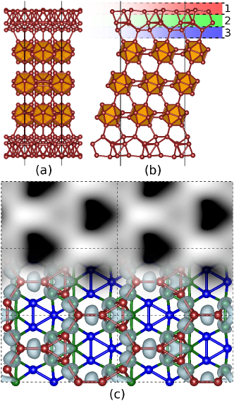
-B is described by cubic close packing of B12 units, while planes of icosahedra are stacked in order along the direction (see Fig. 1 (a) and (b) where the bulk layers are depicted by orange icosahedra). The MHM simulations were conducted on slabs with up to 4-layers of B12 units while at least all atoms in the topmost icosahedral layer were allowed to move during the search. The majority of our simulations were performed on a super-cell generated from the rhombohedral cell vectors , containing atoms and such that a surface area of 62.6 Å2 was covered: , and , for . To prevent interactions with periodic images along the surface-normal direction, initial searches were conducted with a vacuum layer of Å. The final results were obtained with a vacuum space of more than 7 Å, a value at which the surface energy was converged better than 1 meV/Å2. Surface energies were computed according to , where denotes the surface area, is the energy per atom in the crystalline phase (here -B) and is the energy of the slab containing atoms.
Earlier investigations by Hayami et al. Hayami and Otani (2007b) on unreconstructed (111) surfaces indicated a difference in surface energy depending on whether the surface was formed by inter- or intra-icosahedral cuts. According to their results obtained with BLYP, a surface obtained by cutting between icosahedral planes, denoted as (111)-I, would destroy the presumably strong inter-icosahedral bonds and thus lead to a higher surface energy compared to performing a cut through the weaker intra-icosahedral bonds, denoted as (111)-II. However, when reconstructions are permitted, this simple characterization based on bond-breaking can easily fail. In fact, the number of mobile surface atoms is much more important since it can lead to unexpected structural rearrangements and the formation of new, energetically favorable bonds. Therefore, MHM simulations were performed on both the (111)-I and (111)-II surfaces and the results were summarized in table 1. Strikingly, the energetic difference of the unreconstructed (111)-I and (111)-II surfaces depend strongly on the employed exchange-correlation functional (first section in table 1). While PBE, PBEsol, LDA and HSE06 are in good agreement and predict a small energy difference of meV/Å2 between (111)-I and (111)-II, BLYP gives a higher value of meV/Å2, suggesting that the difference between inter- and intra-icosahedral bond energies is less prominent than assumed by Hayami et al. Hayami and Otani (2007b). The lowest energies of the reconstructed surfaces (111)-IR,(a) and (111)-IIR,(a) from the MHM simulations are also summarized in table 1 and clearly show that (111)-IR,(a) is energetically favored, in contrast to the unreconstructed counterparts.
| Surface | PBE | PBEsol | LDA | HSE111Structure relaxed with PBE | BLYP |
| Non-reconstructed | |||||
| (111)-I | 218.8 | 233.3 | 236.5 | 247.5 | 205.4 |
| 220.0222Taken from Ref. Hayami and Otani (2007b) | |||||
| (111)-II | 215.6 | 227.2 | 231.7 | 250.2 | 167.1 |
| 170.0222Taken from Ref. Hayami and Otani (2007b) | |||||
| Reconstructed (111)-I | |||||
| (111)-IR,(a) | 170.6 | 181.6 | 190.4 | 196.3 | |
| (111)-IR,(b) | 172.2 | 182.9 | 192.3 | 198.6 | |
| (111)-IR,(c) | 172.5 | 183.3 | 192.4 | 198.0 | |
| (111)-IR,(d) | 173.1 | 184.1 | 192.7 | 198.4 | |
| (111)-IR,(e) | 173.6 | 184.6 | 192.8 | 198.4 | |
| (111)-IR,(f) | 173.8 | 185.0 | 193.2 | 199.7 | |
| (111)-IR,(g) | 173.8 | 184.8 | 193.3 | 199.2 | |
| (111)-IR,(h) | 174.3 | 185.6 | 192.5 | 198.7 | |
| (111)-IR,(i) | 175.4 | 186.4 | 194.8 | 199.8 | |
| Reconstructed (111)-II | |||||
| (111)-IIR,(a) | 183.0 | 200.8 | 206.6 | 210.0 | |
| Reconstructed (111)-I, atoms added | |||||
| (111)-I | 199.4 | 212.4 | 217.9 | 226.1 | |
| Reconstructed (111)-I, atoms removed | |||||
| (111)-I | 180.4 | 194.6 | 201.3 | 204.6 | |
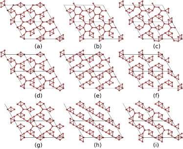
The arrangement of the atoms in the structure (111)-IR,(h) are shown in Fig. 1, where panel (a) and (b) represent the side views along the and the direction, respectively. The three outer atomic layers participate in the reconstruction and are shown separately in panel (c). The first atomic layer, colored in red, forms an almost planar filament of interlinked triangular pattern with symmetry. It is identical for all low energy structures that were found during the MHM simulations, thus providing the fundamental structure to terminate the surface. This first layer is supported by a second atomic layer of higher complexity comprised by a denser network of triangular units (green), thereby forming octahedra together with the triangles from the first layer. The structural variety in this layer however is much larger as illustrated in Fig. 2. The corresponding energies are given in the second section of table 1 which show that the energetic differences resulting from the subtle rearrangements of the triangles are very small, preventing an unambiguous identification of the ground state structure. Finally, the third layer is again identical for all low-energy structures (shown in blue) and are simply the remaining base planes of the underlying icosahedral bulk structure.
In contrast to (111)-IR, the reconstructed (111)-IIR surfaces do not form any planar structures. Since only half of the atoms are available for reconstruction due to the intra-icosahedral truncation, the number of mobile surface atoms is insufficient to satisfy an energetically optimal bonding configuration. Although an additional layer of icosahedra was explicitly included to rearrange during the MHM simulation, the atoms in this layer did not participate in the reconstruction and retained the bulk arrangement. The basic structural motif for all low-energy (111)-IIR surfaces essentially consists of loosely connected nano-ribbons with triangular pattern on top of a perfect icosahedra layer of the bulk slab.
The compositional stability of the surface reconstructions was further investigated by adding and subtracting atoms to the surface layers and performing further MHM simulations (the last two sections of table 1). When depositing atoms (up to 3 atoms per super cell) on the reconstructed surface no structural changes were observed both in the second and third atomic surface layers. The additional atoms clustered on the top layer by forming trigonal structures oriented away from the surface. The surface energy of the lowest structure of this type, (111)-I, was found to be 28.74 meV/Å2 higher in energy than the lowest reconstructed structure (111)-IR,(a). Similarly, removing atoms from the surface layer (up to 3 atoms per super cell) resulted in the reordering of the topmost layer without significantly disturbing the second and third atomic layers. In fact, in the case of removing 3 atoms per super cell, the top layer reconstructed such that a triangular unit was missing, thus destroying an octahedron initially formed together with the second layer. Although still endothermic, the energy difference of (111)-I with respect to the clean slab (111)-IR,(a) is smaller with a value of 9.75 meV/Å2. It can therefore be concluded that the stoichiometry obtained by a planar cut through the bulk is indeed the most stable.
Finally, the electronic structure was studied by investigating the electron localization function (ELF) Silvi and Savin (1994) as implemented in VASP. Fig. 1 (c) shows a corresponding ELF isosurface of the two top atomic surface layers. A clear distinction can be made between 2e2c bonds in the topmost layer connecting the triangular units in the plane, and the polycentric bonds which dominate within all triangular arrangements, especially in the octahedra formed between the first and the second layer. This mixture of covalent 2e2c and polycentric bonding system is characteristic also in the bulk region, where the intra-icosahedral bonds are purely polycentric and inter-icosahedral bonds are either 2-centered (between planes) or 3-centered (within the plane). Additionally, a constant current scanning tunnel microscopy (STM) simulation was performed at a bias of eV based on the Tersoff-Hamann approximation Tersoff and Hamann (1985). The constant current image at a maximal height of Å above the surface was rendered on top of Fig. 1 (c) which can be qualitatively compared to STM experiments .
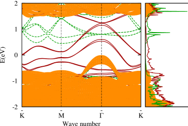
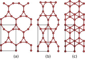
Furthermore, the electronic surface band structure was calculated within the 2D-Brillouin zone for both the reconstructed and the non-reconstructed surface as shown in Fig. 3. The projected band structure of bulk -B, shown as the shaded region in orange, has a PBE band gap with a value of 1.47 eV. When a vacuum is introduced into the material without further reconstruction, the conduction bands decrease and appear as surface states in the gap region which reduce its magnitude to 0.50 eV (shown as dashed, green lines). However, conducting surface states emerge upon allowing the surface to reconstruct, crossing the Fermi level and thus forming a metallic surface (shown as solid, red lines). Since conventional DFT commonly underestimates the band gap additional calculations were performed with the HSE06 hybrid functional, leading to a bulk gap of 2.02 eV and 0.86 eV for the unreconstructed (111)-I. Earlier theoretical works have predicted many 2D boron sheets to be metallic as well Yu et al. (2012); Wu et al. (2012); Lu et al. (2013) such that one way of interpreting the above results is as if a planar, conducting sheet of boron is adsorbed on a (111) -B surface. Based on this perception the stability of the topmost atomic layer was investigated when isolated from the surface. A simple local geometry relaxation was performed in vacuum while allowing the cell to adjust according to the in-plane stresses, starting from the initial structure shown in Fig. 4 (a). As expected, this structure is metallic and transformed to a more compact state upon relaxation to compensate the missing interaction with the substrate. The final structure is shown in Fig. 4 (c), which has previously been predicted to be the ground state in boron sheets at a fixed hole density of , denoted as “struc-1/5” in Ref. Yu et al. (2012). No imaginary phonon frequencies were found in the whole 2D Brillouin zone, indicating that the 2D structure is dynamically stable. The energy difference between (111)-IR,(a) and the isolated sheet plus the optimized, remaining slab is merely 54.4 meV/Å2. This sheet configuration is again metallic and could provide a promising precursor for other boron nano-structures such as single-walled boron nano-tubes or cage-molecules.
In conclusion, an extensive, systematic ab initio structural search was for the first time performed with the MHM on surfaces to identify reconstruction geometries. The main structural motif of the reconstructed (111) surface of -B was isolated, studied and accurately characterized. In contrast to the unreconstructed surface (111)-I, which merely reduces the band gap of crystalline -B, the reconstructed (111)-IR structures contains metallic surface states that facilitates electric conduction. The topmost layers of all low energy reconstructions (111)-IR are planar and consist of a 2D network of interlinked triangular patterns. These results can be interpreted as if a conducting sheet of boron was adsorbed on a semi-conducting substrate, leading to numerous possible applications in nano-electronics. Assuming that it is further possible to isolate the top mono-layer of boron through exfoliation it would provide a 2D boron sheet with hole density as a promising precursor for a large variety of boron nano-structures.
Financial support provided by the Swiss National Science Foundation and French ANR (ANR-08-CEXC8-008-01 and ANR-12-BS04-0001-02) are gratefully acknowledged. Computational resources were provided by the Swiss National Supercomputing Center (CSCS) in Manno and French GENCI (project x2013096017).
References
- Albert and Hillebrecht (2009) B. Albert and H. Hillebrecht, Angew. Chem. Int. Ed. 48, 8640–8668 (2009).
- Oganov et al. (2009) A. R. Oganov, J. Chen, C. Gatti, Y. Ma, Y. Ma, C. W. Glass, Z. Liu, T. Yu, O. O. Kurakevych, and V. L. Solozhenko, Nature 457, 863 (2009).
- Mondal et al. (2011) S. Mondal, S. van Smaalen, A. Schönleber, Y. Filinchuk, D. Chernyshov, S. I. Simak, A. S. Mikhaylushkin, I. A. Abrikosov, E. Zarechnaya, L. Dubrovinsky, and N. Dubrovinskaia, Phys. Rev. Lett. 106, 215502 (2011).
- McCarty et al. (1958) L. V. McCarty, J. S. Kasper, F. H. Horn, B. F. Decker, and A. E. Newkirk, J. Am. Chem. Soc. 80, 2592 (1958).
- Sands and Hoard (1957) D. E. Sands and J. L. Hoard, J. Am. Chem. Soc. 79, 5582 (1957).
- Hughes et al. (1963) R. E. Hughes, C. H. L. Kennard, D. B. Sullenger, H. A. Weakliem, D. E. Sands, and J. L. Hoard, J. Am. Chem. Soc. 85, 361 (1963).
- Laubengayer et al. (1943) A. W. Laubengayer, D. T. Hurd, A. E. Newkirk, and J. L. Hoard, J. Am. Chem. Soc. 65, 1924 (1943).
- Hoard (1951) J. L. Hoard, J. Am. Chem. Soc. Vol: 73 (1951).
- Hoard, Hughes, and Sands (1958) J. L. Hoard, R. E. Hughes, and D. E. Sands, J. Am. Chem. Soc. 80, 4507 (1958).
- Talley, La Placa, and Post (1960) C. P. Talley, S. La Placa, and B. Post, Acta Crystallogr. 13, 271 (1960).
- Vlasse et al. (1979) M. Vlasse, R. Naslain, J. Kasper, and K. Ploog, J. Less Common Metals 67, 1 (1979).
- Boustani and Quandt (1997) I. Boustani and A. Quandt, Europhysics Letters (EPL) 39, 527 (1997).
- Gindulytė, Lipscomb, and Massa (1998) A. Gindulytė, W. N. Lipscomb, and L. Massa, Inorg. Chem. 37, 6544 (1998).
- Boustani et al. (1999) I. Boustani, A. Quandt, E. Hernández, and A. Rubio, J. Chem. Phys. 110, 3176 (1999).
- Ciuparu et al. (2004) D. Ciuparu, R. F. Klie, Y. Zhu, and L. Pfefferle, J. Phys. Chem. B 108, 3967 (2004).
- Liu et al. (2010) F. Liu, C. Shen, Z. Su, X. Ding, S. Deng, J. Chen, N. Xu, and H. Gao, J. Mater. Chem. 20, 2197 (2010).
- Cao et al. (2001) L. M. Cao, Z. Zhang, L. L. Sun, C. X. Gao, M. He, Y. Q. Wang, Y. C. Li, X. Y. Zhang, G. Li, J. Zhang, and W. K. Wang, Adv. Mater. 13, 1701–1704 (2001).
- Otten et al. (2002) C. J. Otten, O. R. Lourie, M.-F. Yu, J. M. Cowley, M. J. Dyer, R. S. Ruoff, and W. E. Buhro, J. Am. Chem. Soc. 124, 4564 (2002).
- Tian et al. (2008) J. Tian, J. Cai, C. Hui, C. Zhang, L. Bao, M. Gao, C. Shen, and H. Gao, Appl. Phys. Lett. 93, 122105 (2008).
- Liu et al. (2008) F. Liu, J. Tian, L. Bao, T. Yang, C. Shen, X. Lai, Z. Xiao, W. Xie, S. Deng, J. Chen, J. She, N. Xu, and H. Gao, Adv. Mater. 20, 2609–2615 (2008).
- Tian et al. (2009) J. Tian, C. Hui, L. Bao, C. Li, Y. Tian, H. Ding, C. Shen, and H.-j. Gao, Appl. Phys. Lett. 94, 083101 (2009).
- Zhu and Kisi (2009) D. Zhu and E. Kisi, J. Aust. Ceram. Soc. 45, 49 (2009).
- Wang et al. (2003) Z. Wang, Y. Shimizu, T. Sasaki, K. Kawaguchi, K. Kimura, and N. Koshizaki, Chem. Phys. Lett. 368, 663 (2003).
- Xu et al. (2004) T. T. Xu, J.-G. Zheng, Wu, A. W. Nicholls, J. R. Roth, D. A. Dikin, and R. S. Ruoff, Nano Lett. 4, 963 (2004).
- Quandt and Boustani (2005) A. Quandt and I. Boustani, ChemPhysChem 6, 2001–2008 (2005).
- Kunstmann, Quandt, and Boustani (2007) J. Kunstmann, A. Quandt, and I. Boustani, Nanotechnology 18, 155703 (2007).
- Tang and Ismail-Beigi (2007) H. Tang and S. Ismail-Beigi, Phys. Rev. Lett. 99, 115501 (2007).
- Tang and Ismail-Beigi (2010) H. Tang and S. Ismail-Beigi, Phys. Rev. B 82, 115412 (2010).
- Yu et al. (2012) X. Yu, L. Li, X.-W. Xu, and C.-C. Tang, J. Phys. Chem. C 116, 20075 (2012).
- Wu et al. (2012) X. Wu, J. Dai, Y. Zhao, Z. Zhuo, J. Yang, and X. C. Zeng, ACS Nano 6, 7443 (2012).
- Lu et al. (2013) H. Lu, Y. Mu, H. Bai, Q. Chen, and S.-D. Li, J. Chem. Phys. 138, 024701 (2013).
- Liu, Penev, and Yakobson (2013) Y. Liu, E. S. Penev, and B. I. Yakobson, Angew. Chem. Int. Ed. 52, 3156–3159 (2013).
- Marques and Botti (2005) M. Marques and S. Botti, J. Chem Phys. 123, 014310 (2005).
- Gonzalez Szwacki, Sadrzadeh, and Yakobson (2007) N. Gonzalez Szwacki, A. Sadrzadeh, and B. I. Yakobson, Phys. Rev. Lett. 98, 166804 (2007).
- Botti et al. (2009) S. Botti, A. Castro, N. N. Lathiotakis, X. Andrade, and M. A. L. Marques, Phys. Chem. Chem. Phys. 11, 4523 (2009).
- Özdoğan et al. (2010) C. Özdoğan, S. Mukhopadhyay, W. Hayami, Z. B. Güvenç, R. Pandey, and I. Boustani, J. Phys. Chem. C 114, 4362 (2010).
- Quarles et al. (2011) K. D. Quarles, C. B. Kah, R. N. Gunasinghe, R. N. Musin, and X.-Q. Wang, J. Chem. Theory Comput. 7, 2017 (2011).
- Pochet et al. (2011) P. Pochet, L. Genovese, S. De, S. Goedecker, D. Caliste, S. A. Ghasemi, K. Bao, and T. Deutsch, Phys. Rev. B 83, 081403 (2011).
- Li et al. (2012) F. Li, P. Jin, D.-e. Jiang, L. Wang, S. B. Zhang, J. Zhao, and Z. Chen, J. Chem. Phys. 136, 074302 (2012).
- Kroto et al. (1985) H. W. Kroto, J. R. Heath, S. C. O’Brien, R. F. Curl, and R. E. Smalley, Nature 318, 162 (1985).
- Vega-Boggio, Schweitz, and Vingsbo (1977) J. Vega-Boggio, J.- . Schweitz, and O. Vingsbo, J. Mater. Sci. 12, 1692 (1977).
- Vega-Boggio and Schweitz (1977) J. Vega-Boggio and J.- . Schweitz, J. Mater. Sci. 12, 1923 (1977).
- Hayami and Otani (2007a) W. Hayami and S. Otani, J. Phys. Chem. C 111, 10394 (2007a).
- Hayami and Otani (2007b) W. Hayami and S. Otani, J. Phys. Chem. C 111, 688 (2007b).
- Oganov (2010) A. R. Oganov, Modern Methods of Crystal Structure Prediction (Wiley-VCH Verlag GmbH, 2010).
- Goedecker (2004) S. Goedecker, J. Chem. Phys. 120, 9911 (2004).
- Amsler and Goedecker (2010) M. Amsler and S. Goedecker, J. Chem. Phys. 133, 224104 (2010).
- Amsler et al. (2012a) M. Amsler, J. A. Flores-Livas, L. Lehtovaara, F. Balima, S. A. Ghasemi, D. Machon, S. Pailhès, A. Willand, D. Caliste, S. Botti, A. San Miguel, S. Goedecker, and M. A. L. Marques, Phys. Rev. Lett. 108, 065501 (2012a).
- Flores-Livas et al. (2012) J. A. Flores-Livas, M. Amsler, T. J. Lenosky, L. Lehtovaara, S. Botti, M. A. L. Marques, and S. Goedecker, Phys. Rev. Lett. 108, 117004 (2012).
- Amsler et al. (2012b) M. Amsler, J. A. Flores-Livas, T. D. Huan, S. Botti, M. A. L. Marques, and S. Goedecker, Phys. Rev. Lett. 108, 205505 (2012b).
- Ghasemi et al. (2008) S. A. Ghasemi, S. Goedecker, A. Baratoff, T. Lenosky, E. Meyer, and H. J. Hug, Phys. Rev. Lett. 100, 236106 (2008).
- Amsler et al. (2009) M. Amsler, S. A. Ghasemi, S. Goedecker, A. Neelov, and L. Genovese, Nanotechnology 20, 445301 (2009).
- Aradi, Hourahine, and Frauenheim (2007) B. Aradi, B. Hourahine, and T. Frauenheim, J. Phys. Chem. A 111, 5678 (2007).
- Kresse and J. (1996) G. Kresse and F. J., Comput. Mat. Sci. 6, 15 (1996).
- Perdew, Burke, and Ernzerhof (1996) J. P. Perdew, K. Burke, and M. Ernzerhof, Phys. Rev. Lett. 77, 3865 (1996).
- Hsing et al. (2009) C. R. Hsing, C. M. Wei, N. D. Drummond, and R. J. Needs, Phys. Rev. B 79, 245401 (2009).
- Perdew et al. (2008) J. P. Perdew, A. Ruzsinszky, G. I. Csonka, O. A. Vydrov, G. E. Scuseria, L. A. Constantin, X. Zhou, and K. Burke, Phys. Rev. Lett. 100, 136406 (2008).
- Heyd, Scuseria, and Ernzerhof (2003) J. Heyd, G. E. Scuseria, and M. Ernzerhof, J. Chem. Phys. 118, 8207 (2003).
- Paier et al. (2006) J. Paier, M. Marsman, K. Hummer, G. Kresse, I. C. Gerber, and J. G. Ángyán, J. Chem. Phys. 125, 249901 (2006).
- Heyd, Scuseria, and Ernzerhof (2006) J. Heyd, G. E. Scuseria, and M. Ernzerhof, J. Chem. Phys. 124, 219906 (2006).
- Becke (1988) A. D. Becke, Phys. Rev. A 38, 3098 (1988).
- Lee, Yang, and Parr (1988) C. Lee, W. Yang, and R. G. Parr, Phys. Rev. B 37, 785 (1988).
- Gonze et al. (2005) X. Gonze, G.-M. Rignanese, M. Verstraete, J.-M. Beuken, Y. Pouillon, R. Caracas, F. Jollet, M. Torrent, G. Zerah, M. Mikami, P. Ghosez, M. Veithen, J.-Y. Raty, V. Olevano, F. Bruneval, L. Reining, R. Godby, G. Onida, D. Hamann, and D. Allan, Z. Kristallogr. 220, 558 (2005).
- Bottin et al. (2008) F. Bottin, S. Leroux, A. Knyazev, and G. Zérah, Comp. Mater. Sci. 42, 329 (2008).
- Silvi and Savin (1994) B. Silvi and A. Savin, Nature 371, 683 (1994).
- Tersoff and Hamann (1985) J. Tersoff and D. R. Hamann, Phys. Rev. B 31, 805 (1985).