AWG-based Non-blocking Clos Networks
Abstract
The three-stage Clos networks remain the most popular solution to many practical switching systems to date. The aim of this paper is to show that the modular structure of Clos networks is invariant with respect to the technological changes. Due to the wavelength routing property of arrayed-waveguide gratings (AWGs), non-blocking and contention-free wavelength-division-multiplexing (WDM) switches require that two calls carried by the same wavelength must be connected by separated links; otherwise, they must be carried by different wavelengths. Thus, in addition to the non-blocking condition, the challenge of the design of AWG-based multistage switching networks is to scale down the wavelength granularity and to reduce the conversion range of tunable wavelength converters (TWCs). We devise a logic scheme to partition the WDM switch network into wavelength autonomous cells, and show that the wavelength scalability problem can be solved by recursively reusing similar, but smaller, set of wavelengths in different cells. Furthermore, we prove that the rearrangeably non-blocking (RNB) condition and route assignments in these AWG-based three-stage networks are consistent with that of classical Clos networks. Thus, the optimal AWG-based non-blocking Clos networks also can achieve 100% utilization when all input and output wavelength channels are busy.
Index Terms:
Clos network, rearrangeably non-blocking (RNB), wavelength-division-multiplexing (WDM), arrayed-waveguide grating (AWG), tunable wavelength converter (TWC)I Introduction
Along with rapid developments in optoelectronic technologies in recent years, wavelength-division-multiplexing (WDM) optical networks have emerged in response to the exponentially growing demand for network capacity. Research in high-speed WDM switch technology is inspired by the immense transmission bandwidth offered by the WDM networks: experiments have demonstrated that an individual optical fiber can carry more than 96 wavelength channels, and each channel can support a data transmission rate up to 100 Gbit/s [1]. Furthermore, considerable progress has been made in photonic devices, among which the combination of the arrayed-waveguide grating (AWG) and the tunable wavelength converters (TWCs) is considered a promising candidate to synthesize WDM switches.
The AWG is a passive optical component with a low insertion loss. Using wavelength routing, the AWG can forward the signal from an input to an output without any contention [2]. The TWC, on the other hand, can convert an input wavelength to any of the output wavelengths in the conversion range. The results reported in [3, 4, 5] demonstrate that the TWC can perform wavelength conversion at speeds of 40 Gb/s, 160 Gb/s and 320 Gb/s. In conjunction with the TWCs, the AWG can perform high-speed packet switching, as demonstrated by the integrated AWG-based switching system described in [3].
Scalability is the key issue that challenges the design of large-scale AWG-based WDM switches. First, the AWG with a large port count suffers from serious coherent crosstalk if the same wavelength is simultaneously fed into more than 15 inputs [6, 7]. This limitation is difficult to resolve through physical design [8]. Second, the cost sharply increases with the conversion range of TWCs in practice [9]. Third, the wavelengths should be fully utilized because wavelengths are the precious resource in the optical communication window [10]. In this paper, the size of the wavelength set associated with the switch is referred to as wavelength granularity.
Scalable large switching networks are usually made by combining multiple stages of small-sized modular switches. The class of non-blocking multistage switching networks was first proposed in 1953 by Charles Clos in his seminal paper [11]. The original three-stage Clos networks remain the most popular solution to many practical switching systems to date. In spite of the rapid developments in integrated circuit and photonic technologies during the last several decades, the theory of Clos networks retains its relevance. The most important characteristic of a Clos network is its modular structure, which is invariant with respect to the technological changes.
In an optimally designed rearrangeably non-blocking (RNB) Clos network, all modular switches and interconnection links are fully utilized when all inputs and outputs are loaded. As for AWG-based Clos networks, the non-blocking condition requires that any two connections from inputs to outputs be either space-interleaved or wavelength-interleaved, i.e., two connections carried by the same wavelength must be connected by separated links, otherwise they must be carried by different wavelengths. To be consistent with the original non-blocking theory of Clos networks, another key issue for constructing AWG-based non-blocking Clos networks is the optimality criterion of network utilization: each component, including AWGs, TWCs, and internal interconnection links, should be fully utilized when all input and output wavelength channels are busy. In respect to these non-blocking criteria, a comparison between previous works and our approach on the design of AWG-based switching networks is described below.
I-A Previous Works
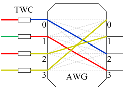
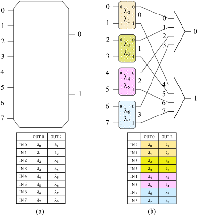
A straightforward construction approach of an AWG-based switching network is to install a TWC at each input of an AWG [3, 12, 13]. The network is logically equivalent to an crossbar and referred to as an AWG-based crossbar. Despite the fact that this network is strictly non-blocking (SNB), it is not scalable because the size of the AWG, the conversion range of the TWCs, and the wavelength granularity are all equal to . When is large, the wavelength granularity of the switching network may be greater than the number of the wavelengths carried by each input or output fiber, and the network suffers from severe crosstalk in AWG and the high cost of the TWC conversion range. Furthermore, the utilization of the AWG is only , because the AWG-based crossbar can only establish connections at most while the AWG can provide interconnections, or wavelength channels, between the inputs and outputs [2] at the same time. An underutilized AWG-based crossbar is depicted in Fig. 1, the dotted gray lines represent idle wavelength channels in the AWG while all inputs are busy.
Several methods have been proposed to suppress the crosstalk of AWG-based switches [7, 14, 15]. A crosstalk-preventing scheduling algorithm was introduced in [7] that prohibits using the same wavelength at more than 15 inputs in an AWG. Despite suppressing coherent crosstalk, this algorithm significantly reduces the number of wavelength channels in an AWG, and requires additional computation complexity to find admissible states. The method introduced in [14] can achieve a zero coherent crosstalk (ZCC) switch by using a restricted subset of AWG inputs. For example, according to this method, a AWG is used to construct a ZCC switch, in which the AWG is severely underutilized yet the required conversion range of the TWCs is greater than 8. The scheme proposed in [15] exploits the wavelengths in multiple free spectrum ranges (FSRs) to prevent using the same wavelength at multiple inputs. This method is not practical because the AWG performs poorly outside the main FSR [16, 17], and the wavelength granularity of the switching network and the conversion range of the TWCs could be several times larger than the port count .
A single-stage network, sandwiching an array of AWG-based crossbars between input fibers and output fibers by a set of interconnection links, was proposed in [9, 18], where each fiber carries wavelengths. This network is typically internally blocking. It is not scalable because the port count of the AWGs, the conversion range of the TWCs, and the wavelength granularity are all equal to , the number of wavelengths per fiber, which could be large in practice. Moreover, the maximum utilization of each AWG is only even when all input and output channels are fully loaded.
The multi-stage AWG-based switching networks were considered in [19, 20, 21], in which a set of AWG-based crossbars are interconnected to form a three-stage rearrangeably non-blocking Clos type network [11]. This switch architecture scales down the size of the AWGs, the conversion range of the TWCs, and the wavelength granularity, but does not fully utilize the wavelength routing properties of the AWGs. In fact, each internal link in this network only carries one wavelength and the routing is performed in the same manner as that in a pure space-division network. As a result, this design exhibits two drawbacks. First, the utilization of the AWGs remains low because each modular switch is an AWG-based crossbar. Second, the physical interconnection complexity is high because the number of links between two adjacent stages is equal to the number of input wavelength channels .
Alternate AWG-based multi-stage networks were proposed in [22, 23, 24, 25], in which each input of the AWGs is equipped with an array of TWCs, such that each internal link carries a set of wavelength channels. These switch architectures were designed to fully utilize the wavelength routing properties of the AWGs and significantly reduce the physical interconnection complexity. Though the switching networks proposed in [24, 25] are non-blocking, the relevant routing algorithms were not presented. Moreover, the size of the AWGs, the conversion range of the TWCs, and the wavelength granularity in these networks are still increasing with respect to the number of the input wavelength channels .
I-B Our Approach and Contribution
This paper illustrates the recursive construction principle of an AWG-based non-blocking Clos network, by taking the network scalability and optimal utilization into consideration. We first apply the technique of modular decomposition of AWGs developed in [2] to the three-stage AWG-based networks. The initial goal of the design is to modularize the AWGs and partition the wavelength set while preserving the wavelength routing properties of AWGs. Next, we introduce the concept of wavelength independence based on the fictitious boundaries that lie in the middle of TWCs. We show that the entire WDM switch network can be divided into wavelength autonomous cells. Consequently, both the wavelength granularity of the network and the conversion range of the TWCs can be substantially reduced by reusing the similar, yet smaller, sets of wavelengths. As for non-blocking route assignments, we show that the rearrangeability of these AWG-based three-stage networks is the same as that of classical Clos networks. In sum, the contribution of this paper is to show that our proposed three-stage AWG-based Clos network can accomplish the following desirable objectives:
-
NB1
The rearrangeably non-blocking (RNB) three-stage network with the minimum number of central modules can achieve 100% utilization when all inputs and outputs are fully loaded,
-
NB2
Modularize AWGs,
-
NB3
Scale down the conversion range of TWCs, and
-
NB4
Reuse the same wavelength set in the recursive construction of the network to reduce the wavelength granularity.
The objective NB1 is consistent with the RNB condition of the traditional Clos networks, while NB2NB4 are additional requirements for WDM-based Clos networks.
The rest of this paper is organized as follows. In Section II, we briefly introduce the function of the AWGs and TWCs, and show how a WDM switching network can be constructed from the combination of AWGs and TWCs. In Section III, we construct a three-stage AWG-based Clos network, based on the non-blocking and contention-free principle of WDM switches. We present the routing algorithm of this network, and show that the network is fully utilized if all input and output wavelength channels are busy. Section IV proposes a recursive construction scheme to achieve the scalability of AWG-based Clos networks. We show that this scheme scales down the AWGs, and substantially reduces wavelength granularity of the network and, thus, the conversion range of the TWCs. Section V concludes this paper with a comparison of our results to previous results.
II Preliminaries
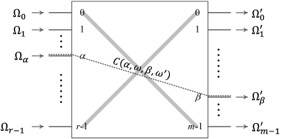
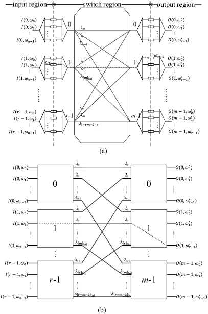
In this paper, we study the wavelength-based communication model [9]. The WDM switch under consideration is illustrated in Fig. 2. This switch has input ports and output ports, and each input port and each output port carries wavelengths and wavelengths, respectively. Thus, the dimension of this WDM switching network is , where is the number of input (output) wavelength channels. The input ports are numbered by from the top to the bottom. The set of wavelengths carried by the input port is denoted by , for . Similarly, the output ports are labeled by , and the set of wavelengths associated with output port is denoted as for . Furthermore, without loss of generality, we assume that input wavelength sets are all the same, (i.e., ), and the output wavelength sets are all the same (i.e., ).
Let denote the input channel at the input port carried by the wavelength , and be the output channel at the output port carried by the wavelength . As illustrated by the dotted line in Fig. 2, a call in the WDM switch is defined as a connection between the input channel and the output channel . This paper focuses on the AWG-based WDM switches with rearrangeably non-blocking (RNB) properties, meaning that a call can always be established between an idle input channel and an idle output channel with possible rearrangements of existing connections. To facilitate our discussion, we first describe the functions of AWG and TWC in a WDM switch.
II-A AWG
An AWG is associated with a set of equally spaced wavelengths in its principal FSR, where . The AWG has a cyclic wavelength routing property: the signal carried by the wavelength at input will be forwarded to output , if
| (1) |
or equivalently,
| (2) |
where . From (2), it is easy to see that each input port of the AWG is associated with a wavelength subset of . Let be the wavelength subset associated with the th input port, where . According to (2), we have
Similarly, let be the wavelength subset associated with the th output port, where . We have
It is clear that . We have shown in [2] that such wavelength assignment of the AWGs is contention-free. As an example, the wavelength assignments of the AWG shown in Fig. 3 are tabulated in a contention-free routing table, in which the output port 2 is associated with the wavelength subset . For a symmetric AWG, the routing table is a Latin square.
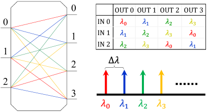
The AWG provides a set of fixed interconnection channels between its input ports and output ports via a group of wavelengths [2]. For example, the 12 interconnection channels between the inputs and the outputs of a AWG are shown in Fig. 3. Larger AWGs can provide much richer interconnection channels; however, the results in [6] show that the AWG with a large port count suffers serious coherent crosstalk, which eventually imposes a limitation on the scalability of AWG-based optical switches [7].
II-B TWC-Module
A set of TWCs sandwiched by a demultiplexer (DeMux) and an optical combiner (Mux) composes an TWC-module, which can convert the wavelengths in the domain set at the input of the DeMux to the wavelengths in the range set at the output of the Mux. Specifically, the function of a TWC-module is to perform a wavelength conversion mapping . The conversion capability of each TWC is characterized by the size of range set , or , which is referred to as the conversion range. An example is the TWC-module shown in Fig. 4(a), where and . In this TWC-module, the conversion range of each TWC is 3, and the wavelengths , , and are converted to , , and , respectively. The wavelength conversion mapping of a TWC-module can also be viewed as a permutation pattern in a crossbar, as shown in Fig. 4(b), where each port represents a wavelength. A TWC with a larger conversion range is more powerful but at a much higher cost [9].
In this paper, we focus on the recursive construction of modular WDM switch architectures, in which the wavelength sets associated with different modular switches must be independent of each other. Therefore, it is sometimes necessary to separate the domain set and the range set of a TWC-module. Logically, a TWC-module can be divided by a fictitious boundary into two parts, the L-TWC-module and the R-TWC-module, as indicated by the dashed line displayed in Fig. 4(a), while the conversion mapping is performed at the boundary between the L-TWC-module and the R-TWC-module.
II-C Two-Stage AWG-Based Network
In this part, we consider a WDM switch that is composed of a single AWG and a set of TWC-modules. In this switch, each input port is equipped with an input TWC-module, and each output port is equipped with an output TWC-module. This WDM switch is associated with a wavelength set , and thus its wavelength granularity is . The labeling of input TWC-modules and output TWC-modules is displayed in Fig. 5(a). This network is referred to as a two-stage AWG-based network and denoted by .
The task of the TWC-modules is to perform wavelength conversions. Let and be the wavelength sets carried by input and output channels, respectively. In the input TWC-module , the input channels carried by the wavelengths in the set are fully demultiplexed by the L-TWC-module, and their wavelengths are converted to the wavelengths in the set , i.e., performing the wavelength mapping , where . Similarly, in the output TWC-module , the wavelength mapping is carried out at the boundary. The wavelengths in the set are multiplexed together by the R-TWC-module and fed to the output port. Therefore, through wavelength conversions, the input and output TWC-modules form two fictitious boundaries that separate the network into three parts: input wavelength region, switch wavelength region, and output wavelength region, which are associated with , , and , respectively.
According to the wavelength routing property of AWGs defined by (2), there is a unique connection between each input TWC-module and each output TWC-module in this switch. A call request from the input channel to the output channel , denoted as , can be established according to (2) by the wavelength in the AWG, where . The input TWC-module translates the input wavelength to , and the output TWC-module converts to the output wavelength . The route and wavelength assignment (RWA) for the call can be expressed as follows:
which is also illustrated in Fig. 5(a). On the other hand, since only one wavelength can be assigned to a paired input TWC-module and output TWC-module, this two-stage AWG-based network is internally blocking. Two input channels that share the same input TWC-module cannot be switched to the same output TWC-module at the same time. The reason that the two-stage AWG network is blocking is logically equivalent to that of a Banyan network [26]. The analogy between the two-stage AWG network and the Banyan network is shown in Fig. 5(b), which demonstrates the following one-to-one correspondences between these two networks:
-
(1)
a crossbar module and a TWC-module,
-
(2)
an input/output port and an input/output wavelength,
-
(3)
a link between the crossbars at two adjacent stages and a wavelength route in the AWG.
Therefore, the two-stage AWG-based network is also referred to as AWG-based Banyan network in this paper. In the next section, we show that a non-blocking WDM switch can be realized by a three-stage AWG-based Clos network, which is the cascaded combination of two AWG-based Banyan networks.
III Rearrangeably Non-blocking AWG-Based Three-Stage Networks
In this section, we explore the recursive construction of AWG-based three-stage networks. Since connections carried by different wavelengths can be multiplexed into a single link, the non-blocking condition of a WDM switch is different from that of a space-division network. Specifically, the following fundamental constraint is imposed on all connections in a multi-stage non-blocking WDM switch network:
Non-blocking and Contention-free Principle of WDM Switches: If two connections share a common link, then they must be carried by different wavelengths, or equivalently, calls carried by the same wavelength must be connected by separated links.
As Section II illustrates, the AWG-based Banyan network is internally blocking because there is only one link between each input TWC-module and each output TWC-module. In a three-stage network, similar to the space-division Clos network, the number of alternative paths between a pair of input and output TWC-modules can be increased by the cascaded combination of two AWG-based Banyan networks. Furthermore, we show in this section that the non-blocking three-stage AWG-based network with the minimum number of central modules can accomplish the desirable objectives NB1NB4 mentioned in Section I.
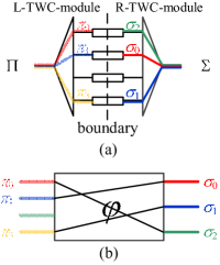
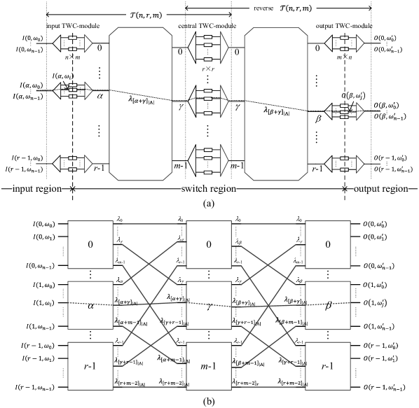
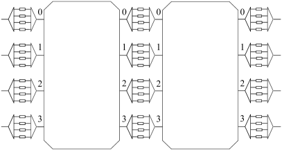
The three-stage AWG-based network under consideration, as shown in Fig. 6(a), is a combination of a network and a reverse network, denoted as , where is the number of wavelength channels and is the number of central TWC-modules. The wavelength granularity of the network is , which is the same as that of the . The two fictitious boundaries in the middle of the input and output TWC-modules are represented by the two dashed lines in Fig. 6(a). They divide the entire network into three wavelength independent regions, corresponding to the external input wavelength set , the switch wavelength set , and the external output wavelength set , respectively.
In the network , an input channel on the input TWC-module and an output channel on the output TWC-module can be connected via a central TWC-module , for . According to the wavelength routing property of the AWG, the central TWC-module is connected to the input TWC-module by wavelength , and the output TWC-module by wavelength , where the indices are given by
| (3) |
and
| (4) |
The wavelength is converted to in the middle by the central TWC-module . The connection of the call , as shown in Fig. 6, is given by:
which contains the following sequence of wavelength conversions:
-
•
input TWC-module ,
-
•
central TWC-module ,
-
•
output TWC-module .
Furthermore, if we replace every TWC with a crossbar switch, the is logically equivalent to a symmetric three-stage Clos network [26] with the inter-stage connections specified by (3) and (4) as shown Fig. 6(b).
Similar to the non-blocking condition of Clos networks, two calls and in the cannot share the same central TWC-module if they are from the same input TWC-module, i.e., , or if they are destined for the same output TWC-module, i.e., . It follows that the contentions among calls in the can be modeled as a bipartite graph , in which the vertex and the vertex denote the input TWC-module and the output TWC-module , respectively, and a call is represented by an edge that connects and . The bipartite graph is -regular with vertices and edges if all input and output wavelength channels in the network are busy.
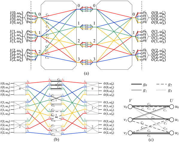
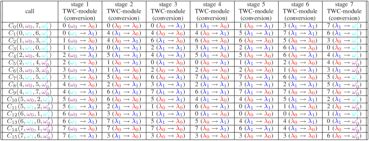
Let be a set of colors, such that each color corresponds to a central TWC-module . The fact that two calls in conflict cannot share the same central TWC-module corresponds to the condition that two edges terminated on the same vertex in cannot be colored with the same color. Thus, the RWA problem of can be solved by the edge coloring of the bipartite graph . As an example, we consider the calls in the network shown in Fig. 7(a), in which the connections were established by the 4-edge coloring of the bipartite graph displayed in Fig. 7(c). In this example, the four central TWC-modules, namely 0, 1, 2, and 3, are represented by color , , , and , respectively. According to the edge coloring shown in Fig. 7(c), the corresponding route assignments, as illustrated in Fig. 7(b), are given in Table I. Once the central module assigned to each call is fixed, the wavelengths that carry out the connections can be immediately determined by (3) and (4), which are also shown in Table I.
Many efficient algorithms for edge coloring of bipartite graphs are available. For example, using the edge coloring algorithms reported in [27] and [28] to color the bipartite graph of the network , the time complexities are on the order of and , respectively. If the switch contains central TWC-modules and is an integral power of 2, then the time complexity can be further reduced to by using the algorithm described in [29]. Heuristic algorithms for bipartite matching, such as iSLIP [30] and DRRM [31], are also available for online implementation of packet switching systems.
In graph theory, the chromatic index of a graph is the minimum number for which is -edge colorable. From Hall’s theorem [32], it is easy to prove that the chromatic index of a bipartite graph is equal to the maximum vertex degree of . Since the bipartite of the network has a maximum vertex degree , we immediately obtain the following condition on RNB networks.
Theorem 1
The network is RNB if and only if .
In classic Clos networks, the proof of the above theorem was originally given by Slepian [33] and Duguid [34]. Their proof of the theorem is actually a rearrangement algorithm for blocked calls. The same algorithm can be applied to the network in case blocking occurred. According to the above theorem, the minimum number of central TWC modules required by a rearrangeably non-blocking network is , in which case the network has exactly TWCs at each stage and wavelength channels within each AWG. Thus, similar to the symmetric rearrangeably non-blocking (RNB) Clos networks with minimum number of central modules, the optimal network can also achieve 100% utilization when all inputs and outputs are fully loaded with calls.
| Input | Central TWC-module | output | |
| call | TWC-module | (wavelength conversion) | TWC-module |
| 0 | 0 () | 0 | |
| 1 | 0 () | 1 | |
| 2 | 0 () | 2 | |
| 0 | 1 () | 1 | |
| 1 | 1 () | 0 | |
| 2 | 1 () | 2 | |
| 0 | 2 () | 1 | |
| 1 | 2 () | 0 | |
| 2 | 2 () | 2 | |
| 0 | 3 () | 0 | |
| 1 | 3 () | 1 | |
| 2 | 3 () | 2 |
The major goal of the classic three-stage Clos networks is to scale crossbar modules by using a recursive decomposition scheme. However, the AWGs and the conversion range of central TWC-modules in the network are not scalable. It also emerged as the most intractable issue of similar AWG-based three-stage networks proposed in [24] and [25]. The complete recursive scheme to achieve the scalability of AWG-based Clos networks is described in the next section.
IV Recursive Construction: AWG Modularization and Wavelength Reuse
To achieve our objective NB2NB4, we focus our discussion on the modularization of AWGs and the rule to reduce the conversion range of the central TWCs. Without loss of generality, we consider the recursive construction of the network with parameter . An example network is illustrated in Fig. 8, where and . This three-stage switch network consists of an input AWG and an output AWG with the wavelength set in the switch region. Thus, the wavelength granularity of the network is . Also, the conversion range of each input or output TWC is , while that of central TWCs is .
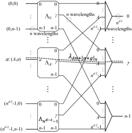
We first consider the decomposition of an AWG into a two-stage network, denoted as . As shown in Fig. 9, the network consists of AWGs in the first stage and Muxes in the second stage. In the two-stage network, the input is labeled by the two-tuple , where and , to indicate that it is the th input of the th AWG module. Herein, denotes the largest integer smaller than . The set of wavelengths associated with AWG is a subset , defined by
| (5) |
for . In the second stage of the network, the th output of the AWG and the th input of the Mux are connected by an internal link, which carries a stream of signals with wavelength set . The following path, denoted as , from input to output :
is connected through the wavelength , where
| (6) | |||||
Similar to the three-stage decomposition of AWGs described in [2], the path in the two-stage determined by the wavelength routing (6) are contention-free at both inputs and outputs, as illustrated in the proof of the following lemma.
Lemma 1
The network is functionally equivalent to an AWG.
Proof:
Each input and each output of the network are connected by the path . We want to show that these paths are contention-free at each input and each output if wavelength routing follows the rule specified by (6).
Suppose that the two connections and are originated at the same input , then we have
If and are routed by the same wavelength , then, from (6), we have
which implies , because . It follows that and are the same connection. Thus, all inputs are contention-free.
Similarly, suppose that the two connections and are destined for the same output, i.e., and use the same wavelength . Then, according to (6), we have
which implies , because . We therefore have
which implies , because . Again, the two connections and must be the same, and all outputs are also contention-free. ∎
The decomposition of an AWG into the two-stage network is illustrated in Fig. 10. The network consists of four AWGs in the first stage and two Muxes in the second stage. The original wavelength set is partitioned into four subsets , , , and , associated with the four corresponding AWGs.
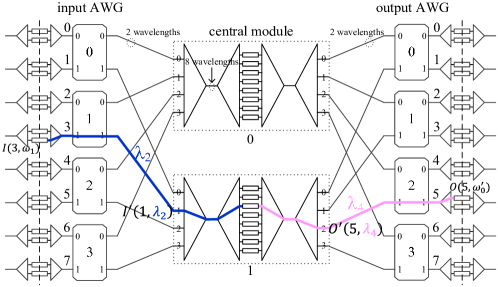
Similarly, it is easy to show that an AWG can be decomposed into a functionally equivalent two-stage network , which is a mirror image of the network . According to Lemma 1, if the two AWGs in are replaced by the corresponding networks and , then we obtain an equivalent three-stage network, denoted as . For example, the network shown in Fig. 11 is equivalent to the network displayed in Fig. 8. The AWGs in are referred to as input AWGs, and those in are output AWGs. In the network , there are central modules and they possess the following properties:
-
P1
There is a unique link between each AWG and each central module,
-
P2
Each central module is an WDM switch, which consists of an Mux, a central TWC-module, and a DeMux,
-
P3
Each central module is functionally equivalent to an crossbar, where each input or output of the central module carries wavelengths, and there are TWC converters with the conversion range of ,
-
P4
Each central module employs the entire wavelength set . According to the non-blocking and contention-free principle, this wavelength set is not scalable because the single link in each Mux/DeMux pair carries all wavelengths in .
Note that the property P4 implies that the wavelength granularity of the network is , the same as that of the network .
In the network shown in Fig. 11, the connection of the call yields a sub-call from to in the central module 1. Generally, in the network , a stereotyped connection of the call via central module will incur a sub-call , as shown in Fig. 12. In the central module , the parameters , , , and of this sub-call are given by
| (7) |
| (8) |
| (9) |
and
| (10) |
Despite the fact that the AWGs are modularized in the network , it is still not a recursive decomposition scheme because the central modules do not repeat the same three-stage structure of the entire network. In addition, the wavelength set and the conversion range of TWCs are not scalable due to the properties P3 and P4 above. According to the non-blocking and contention-free principle, different input (output) AWGs can reuse the same wavelength set only if they are either topologically independent or separated by fictitious boundaries of TWCs.
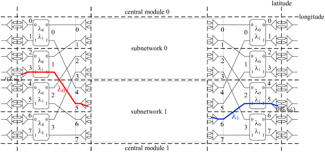
To achieve the wavelength reuse and retain the properties P1 and P2 above, we can logically divide the network into disjoint cells by the vertical fictitious boundaries in the middle of TWCs, and the horizontal dashed lines between AWG modules. As Fig. 13 illustrates, the wavelengths used by the part of each central module between the two boundaries, referred to as a sub-network, can be independent of those wavelength sets associated with the AWGs and the TWCs outside these boundaries. If each sub-network repeats the same three-stage structure of the entire network, we then have a recursively constructed three-stage network, denoted as . Moreover, in this three-stage network, all input and output TWC-modules and all input and output AWGs can use the same wavelength set, e.g., , because they are either topologically independent or separated by fictitious boundaries. It follows that the wavelength granularity of the is , much smaller than that of the network and . For example, every cell in the shown in Fig. 13 uses the same wavelength set .
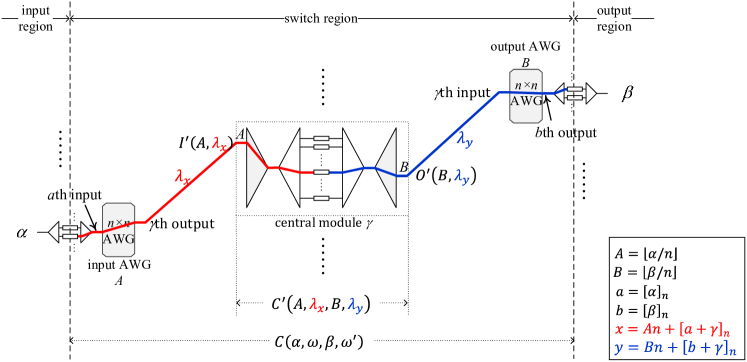
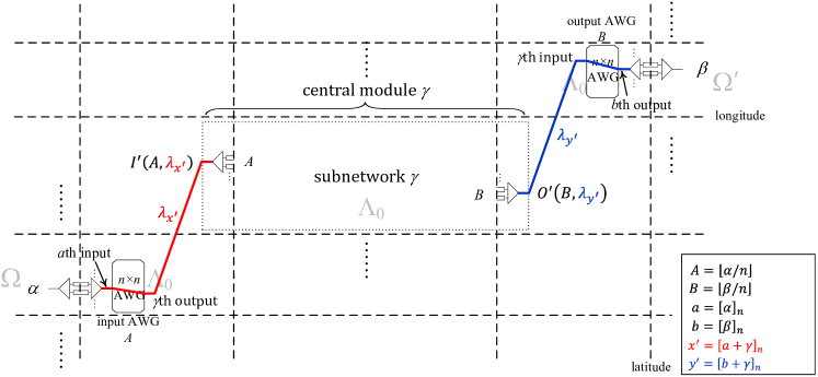
The connection of a call in the network is similar to that in the described before. As an example, Fig. 13 illustrates the connection of the call in the network . In general, the connection of a call via central module in the network , as Fig. 14 shows, can be expressed by
where and are given as follows:
| (11) |
and
| (12) |
Similarly, in the network , a sub-call will be incurred in the central module by this connection of the call .
Collecting the above discussions, we conclude this section in the following theorem.
Theorem 2
The network is an RNB network that achieves the objective NB1NB4.
Proof:
Since the number of central modules in the three-stage network is , according to Theorem 1, it is RNB if every central module is RNB. In addition, according to Lemma 1, the wavelength assignments based on (11) and (12) are contention-free. Next, we want to show that the objective NB1NB4 can be achieved by this recursive network.
In the network , there are input (output) TWC-modules that totally contain TWCs, and input (output) AWGs. When all wavelength channels are active, all input (output) TWCs and all input (output) AWGs of the network are fully occupied. Also, as we discussed above, all TWCs and AWGs are associated with the same wavelength set , as Fig. 14 illustrates. Thus, the first and third stages of the network fulfill the objective NB1NB4. Moreover, each sub-network in the central module repeats the same three-stage structure of the entire network, and the wavelengths used by the sub-networks are independent of those wavelength sets associated with the TWCs and AWGs outside these boundaries. It follows that all central modules can also fulfill these objectives if we repeatedly apply the recursive decomposition scheme to each central module. ∎
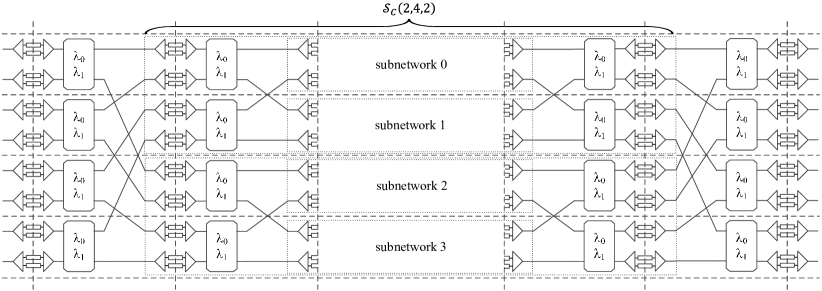
An example is illustrated in Fig. 15, which is obtained by the decomposition of the central modules of network shown in Fig. 13. It is clear that all TWC-modules and AWG modules can be associated with the same wavelength set , and fulfill the objective NB1NB4.
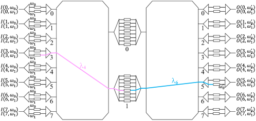
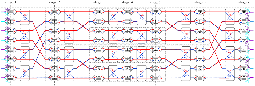
Repeatedly applying the recursive scheme, a WDM network with input and output channels can be constructed by TWC-modules and AWGs associated with a set of wavelengths . In particular, if we apply the decomposition scheme times to the network , then we obtain an AWG-based three-stage network denoted as , which consists of columns of TWC-modules and columns of AWGs. Clearly, the wavelength granularity of the network is , which is only of that of the network . For example, the network shown in Fig. 16(a) is the AWG-based three-stage network with wavelength granularity 2. The route and wavelength assignments tabulated in Fig. 16(b) illustrate that the AWG-based three-stage network can achieve 100% utilization when all input wavelength channels are busy.
Therefore, an AWG-based three-stage network can be recursively constructed from a set of AWGs together with a collection of TWCs with conversion range , where . There is an inherent tradeoff between the physical interconnection complexity and the wavelength granularity in the AWG-based WDM switches, and this point can be demonstrated by a comparison between the network shown in Fig. 16(a) and the network displayed in Fig. 17. The number of interconnection links between two adjacent stages in an electronic three-stage network is or , while the counterpart in an AWG-based three-stage network is , because each link in can simultaneously carry wavelength channels. This reduction factor of interconnection complexity can be significant if is large, which is achieved at the expense of increasing the size of AWG modules and the conversion range of TWCs.
| NB1 | NB2 | NB3 | NB4 | physical | |
| Schemes | (100% utilization) | (modular AWG) | (scalable TWC) | (wavelength reuse) | interconnection complexity |
| AWG-based Crossbar | |||||
| [3, 7, 12, 13, 14, 15] | no | no | no | no | |
| Single-stage network | |||||
| [9] | no | no | no | no | |
| Multi-stage network | |||||
| [19, 20, 21] | no | yes | yes | yes | |
| [24, 25], Theorem 1 | yes | no | no | no | |
| yes | yes | no | no | ||
| , Theorem 2 | yes | yes | yes | yes |
In the practical implementation of the AWG-based three-stage network , due to current state of art, we should take the following limitations into consideration:
-
1)
Coherent crosstalk: Let (in dB) be the power penalty induced by the coherent crosstalk of an AWG when all input wavelengths are the same. Since there are stages of AWGs in an network, the overall power penalty of each connection is if there is no compensation mechanism within the network;
-
2)
Amplified spontaneous emission (ASE) noise: Semiconductor optical amplifiers (SOAs) are the key components of a compact all-optical TWC. The ASE noise generated by SOAs will decrease the optical signal-to-noise ratio (OSNR). Therefore, if SOA-based all-optical TWCs without regenerative function are used, then the OSNR will be faded with the increasing number of stages;
-
3)
Insertion loss: A typical AWG has a 6-dB insertion loss.
These limitations could be relaxed as follows. First, keep smaller than 15 [6] such that the coherent crosstalk can be compensated at the outputs of each AWG. Second, use all-optical regenerative TWCs [35, 36] or optic-electron-optic (O-E-O) TWCs [3] in the network such that 3R signal regenerations can be performed stage by stage. In practice, it is feasible to use O-E-O TWCs now because high-speed (100 GHz) transceivers are already commercially available.
With the maturity of photonics integrated circuits, the modular construction of an optical switch by using optical integrated modules is gradually workable. For example, the AWG-based crossbar on a III/V photonics chip reported in [3] demonstrates the feasibility of the integration of each stage of the network on a single photonics chip. However, it is still difficult to integrate the entire optical switch network, including the optical switching fabric and the electronic controller, on a single chip based on silicon-on-insulate (SOI) technology, despite the fact that the silicon-based AWGs [37], and the silicon-based modulator and detector [38], the key component of the O-E-O TWC, are both commercially available. The bottleneck is the unexplored technique of a silicon-based optical laser, an essential component of the TWC. Another challenge of the integration on a single chip is that of the crosspoints of the interconnection links between two adjacent stages, since additional crosstalk and loss could be incurred if the number of crosspoints is too large.
V Conclusion
This paper proposes a recursive scheme for the construction of AWG-based non-blocking Clos networks. In respect to the network scalability and optimal utilization criteria, this recursive approach outperforms the previous schemes in the following aspects. First, it can construct a large-scale network by a collection of small-sized AWGs while preserving the complete wavelength routing property. Second, it logically divides the WDM switch network into wavelength independent cells, such that a similar, but smaller, set of wavelengths can be reused by these cells, which substantially scales down the wavelength granularity and the conversion range of TWCs. Third, the route assignments in these recursive networks are consistent with those in the classical Clos networks, and thus the optimal AWG-based RNB Clos network can achieve 100% utilization when all input and output wavelength channels are busy. For comparison purposes, Table II lists all known results on the AWG-based multistage networks.
References
- [1] M. Salsi et al., “Transmission of 96100Gb/s with 23% super-FEC overhead over 11,680km, using optical spectral engineering,” in Proc. OFC, 2011, p. OMR2.
- [2] T. Ye, T. T. Lee, and W. Hu, “A study of modular AWGs for large-scale optical switching systems,” J. Lightw. Technol., vol. 30, no. 13, pp. 2125–2133, Jun. 2012.
- [3] D. J. Blumenthal et al., “Integrated photonics for low-power packet networking,” IEEE J. Sel. Topics Quantum Electron., vol. 17, no. 2, pp. 458–471, Mar./Apr. 2011.
- [4] Y. Liu et al., “Error-free all-optical wavelength conversion at 160 Gb/s using a semiconductor optical amplifier and an optical bandpass filter,” J. Lightw. Technol., vol. 24, no. 1, pp. 230–236, Jan. 2006.
- [5] ——, “Error-free 320-Gb/s all-optical wavelength conversion using a single semiconductor optical amplifier,” J. Lightw. Technol., vol. 25, no. 1, pp. 103–109, Jan. 2007.
- [6] R. Gaudino, G. A. G. Castillo, F. Neri, and J. M. Finochietto, “Simple optical fabrics for scalable terabit packet switches,” in Proc. IEEE ICC, 2008, pp. 5331–5337.
- [7] A. Bianco, D. Hay, and F. Neri, “Crosstalk-preventing scheduling in single and two-stage AWG-based cell switches,” IEEE/ACM Trans. Netw., vol. 19, no. 1, pp. 142–155, Feb. 2011.
- [8] V. Mikhailov, C. Doerr, and P. Bayvel, “Ultra low coherent crosstalk, high port-count free-space wavelength router,” in Proc. OFC, Mar. 2003, pp. 257–258.
- [9] A. Pattavina and R. Zanzottera, “Non-blocking WDM switches based on arrayed waveguide grating and shared wavelength conversion,” in Proc. IEEE INFOCOM, 2006.
- [10] G. Weichenberg, V. W. S. Chan, and M. Gedard, “Design and analysis of optical flow-switched networks,” IEEE J. Opt. Commun. Netw., vol. 1, no. 3, pp. B81–B97, Aug. 2009.
- [11] C. Clos, “A study of nonblocking switching networks,” Bell System Technology Journal, vol. 32, no. 2, pp. 406–424, Mar. 1953.
- [12] J. Cheyns et al., “Routing in an AWG-based optical packet switch,” Photon. Network Commun., vol. 5, pp. 69–80, Jan. 2003.
- [13] Z. Pan et al., “Advanced optical-label routing system supporting multicast, optical TTL, and multimedia applications,” J. Lightw. Technol., vol. 23, no. 10, pp. 3270–3281, Oct. 2005.
- [14] D. Lucerna, G. Maier, and A. Pattavina, “AWG-based architecture for optical interconnection in asynchronous systems,” in Proc. IEEE HPSR, 2011, pp. 250–255.
- [15] M. Maier, M. Reisslein, and A.Wolisz, “High-performance switchless WDM network using multiple free spectral ranges of an arrayed-waveguide grating,” in Proc. SPIE Photonics East Terabit Optical Networking: Architecture, Control, and Management Issues, vol. 4213, 2000, pp. 101–112.
- [16] S. Kamei, M. Ishii, A. Kaneko, T. Shibata, and M. Itoh, “NxN cyclic-frequency router with improved performance based on arrayed-waveguide grating,” J. Lightw. Technol., vol. 27, no. 18, pp. 4097–4014, Sep. 2009.
- [17] F. Liu, R. J. S. Pedersen, and P. Jeppesen, “Very low crosstalk wavelength router construction using arrayed-waveguide grating multi/demultiplexers,” Electron. Lett., vol. 35, pp. 839–840, May 1999.
- [18] J. Ramamirtham and J. S. Turner, “Design of wavelength converting switches for optical burst switching,” in Proc. IEEE INFOCOM, 2002, pp. 1162–1171.
- [19] J. Cheyns et al., “Clos lives on in optical packet switching,” IEEE Commun. Mag., vol. 42, no. 2, pp. 114–121, Feb. 2004.
- [20] H. Q. Ngo, D. Pan, and C. Qiao, “Constructions and analyses of nonblocking WDM switches based on arrayed waveguide grating and limited wavelength conversion,” IEEE/ACM Trans. Netw., vol. 14, no. 1, pp. 205–217, Feb. 2006.
- [21] R. Zanzottera et al., “Design of OXC architectures based on arrayed waveguide gratings: Topological properties and physical performance,” in Proc. IEEE HPSR, 2006.
- [22] S. Bregni, A. Pattavina, and G. Vegetti, “Architectures and performance of AWG-based optical switching nodes for ip networks,” IEEE J. Sel. Areas Commun., vol. 21, no. 7, pp. 1113–1121, Sep. 2003.
- [23] M. Maier and M. Reisslein, “AWG-based metro WDM networking,” IEEE Commun. Mag., vol. 42, no. 11, pp. s19–s26, Nov. 2004.
- [24] W. D. Zhong, J. P. Lacey, and R. Tucker, “Multiwavelength cross-connects for optical transport networks,” J. Lightw. Technol., vol. 14, no. 7, pp. 1613–1620, Jul. 1996.
- [25] J. J. G. Leonardus, “Non-blocking cyclic AWG-based node architectures,” EU patent: EP1761103, Mar. 2007.
- [26] T. T. Lee and S. C. Liew, Principle of broadband switching and networking. Wiley-Interscience, 2010, ch. 2.
- [27] R. Cole, K. Ost, and S. Schirra, “Edge-coloring bipartite multigraphs in time,” Combinatorica, vol. 21, no. 1, pp. 5–12, Jan. 2001.
- [28] T. T. Lee, Y. Wan, and H. Guan, “Randomized -edge colouring via exchanges of complex colours,” International Journal of Computer Mathematics, vol. 90, no. 2, pp. 228–245, Feb. 2013.
- [29] T. T. Lee and S. Y. Liew, “Parallel routing algorithms in Benes-Clos network,” IEEE Trans. Commun., vol. 50, no. 11, pp. 1841–1847, Nov. 2002.
- [30] N. McKeown, “The iSLIP scheduling algorithm for input-queued switches,” IEEE/ACM Trans. Netw., vol. 7, no. 2, pp. 188–201, Apr. 1999.
- [31] H. J. Chao, C. Lam, and E. Oki, Broadband packet switching technologies - a practical guide to ATM switches and IP routers. Wiley, 2001.
- [32] P. Hall, “On representatives of subsets,” J. London Math Soc., vol. 10, pp. 26–30, 2003.
- [33] D. Slepian, “Two theorems on a particular crossbar switching network,” 1952, unpublished manuscript.
- [34] A. M. Duguid, “Structural properties of switching networks,” Brown University, Tech. Rep., 1959, bTL-7.
- [35] H. Chayet et al., “Regenerative all-optical wavelength converter based on semiconductor optical amplifier and sharp frequency response filter,” in Proc. OFC, 2004, p. ThS2.
- [36] C. Porzi, A. Bogoni, and G. Contestabile, “Regenerative wavelength conversion of DPSK signals through FWM in an SOA,” IEEE Photon. Technol. Lett., vol. 25, no. 2, pp. 175–178, Jan. 2013.
- [37] S. T. Cheung et al., “Low-loss and high contrast silicon-on-insulator (SOI) arrayed waveguide grating,” in Proc. CLEO, 2012, p. CM4A.5.
- [38] A. Dhiman, “Silicon photonics: a review,” IOSR Journal of Applied Physics, vol. 3, no. 5, pp. 67–79, Mar./Apr. 2013.