Exhibition of circular Bragg phenomenon by hyperbolic, dielectric, structurally chiral materials
Akhlesh Lakhtakia
National Taipei University of Technology, Department of Electro-Optical Engineering, Taipei 106, Taiwan
and
Pennsylvania State University, Department of Engineering Science and Mechanics, University Park, Pennsylvania 16802–6812, USA
Abstract
The relative permittivity dyadic of a dielectric structurally chiral material (SCM) varies helicoidally along a fixed direction; in consequence, the SCM exhibits the circular Bragg phenomenon, which is the circular-polarization-selective reflection of light. The introduction of hyperbolicity in an SCM—by making either one or two but not all three eigenvalues of the relative permittivity dyadic acquire negative real parts—does not eliminate the circular Bragg phenomenon, but significantly alters the regime for its exhibition. Physical vapor deposition techniques appear to be suitable to fabricate hyperbolic SCMs.
Keywords: circular Bragg phenomenon, hyperbolic dispersion, indefinite permittivity, structural chirality
1 Introduction
Chiral liquid crystals [1, 2] and chiral sculptured thin films [3, 4] are dielectric examples of structurally chiral materials (SCMs)—which are anisotropic and helicoidally nonhomogeneous along a fixed axis. If that fixed axis is parallel to the axis of a Cartesian coordinate system with unit vectors , , and , the frequency-domain constitutive relations of dielectric SCMs may be set down as
| (1) |
where the superscript T denotes the transpose; and are the permeability and permittivity of free space; the rotational nonhomogeneity is expressed through the dyadic
| (2) |
with as the helical pitch and either for structural right-handedness or for structural left-handedness; the dyadic
| (3) |
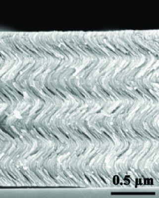
containing as the angle of rise of the helical morphology; and , , and are the three -independent eigenvalues of the relative permittivity dyadic . Typically, dissipation is small enough to be ignored and ; hence, is positive definite [5]. Figure 1 shows a cross-sectional image of a chiral sculptured thin film.
The optical signature of an SCM is a circular-polarization-sensitive stopband. The center wavelength and the width of this stopband depend on the direction of the wavevector of an incident circularly polarized plane wave. Most significantly, the stopband is exhibited when the incident plane wave’s handedness is the same as the structural handedness of the SCM, but not otherwise. The stopband is best seen when the thickness of the SCM exceeds a certain number of helical pitches [6, 7, 8, 9]. When dissipation is small enough to be ignored, is positive definite, and the variations of with respect to the free-space wavelength are also small enough to be ignored, the circular-polarization-sensitive stopband can be delineated as [4]
| (4) |
where is the angle of incidence with respect to the axis and
| (5) |
Provided that for all , the estimates (4) can be used with replaced by and by . The exhibition of the circular-polarization-sensitive stopband is called the circular Bragg phenomenon.
During the last ten years, attention has been paid to dielectric-magnetic materials with indefinite permeability and permittivity dyadics [10, 11]. Although the practical realization of such materials remains a matter of conjecture, there is no doubt on the existence in nature of dielectric materials the real parts of whose permittivity dyadics are indefinite [5]. Graphite [12], triglycine sulfate [13, 14], sapphire [15], and bismuth [14] are examples. Metal nanowire arrays [16] and periodic metal/dielectric multilayers [17] provide examples of manufactured anisotropic dielectric materials whose effective permittivity dyadics have indefinite real parts [18]. Periodic graphene/dielectric multilayers have also been profferred as candidates [19]. Although dissipation due to conduction in metals and graphene has been predicted to be offset-able by using dielectric materials with optical gain [20], the effective-medium approximations underlying such predictions must be handled with some care [21].
Experience with ambichiral materials [22, 23] indicates that hyperbolic, dielectric SCMs ought to be practically realizable as nanoengineered periodic multilayers. A variety of physical deposition techniques—such as thermal evaporation, electron-beam evaporation, and sputtering [24]—can be used to deposit alternating layers of a metal and a dielectric material on a suitably rotating planar substrate [4]. In these fabrication techniques, collimated vapor fluxes of both materials must be directed very obliquely towards the substrate in order to engender biaxiality. Furthermore, the nominal thickness of each metal layer must be a small fraction of the nominal thickness of each dielectric layer [21], and all layers must be electrically thin [25, 26]. Either one or two of , , and would be negative, with the remainder being positive. Then, with dissipation assumed to be sufficiently small, the estimates (4) would become dubious. Indeed, the question arises: will a hyperbolic SCM exhibit the circular Bragg phenomenon?
In order to answer this question, a one-point boundary-value problem was formulated and solved. In this problem, the half space is vacuous while the half space is occupied by the hyperbolic SCM, and a circularly polarized plane wave is obliquely incident on the interface from its vacuous side. As it is known that the circular Bragg phenomenon develops as the thickness of an SCM increases [7, 4], an SCM half space should conceptually deliver the best developed circular Bragg phenomenon. The underlying boundary-value problem is introduced briefly in Sec. 2, the detailed procedure to solve it being available elsewhere [27]. Numerical results are provided and discussed in Sec. 3. An dependence on time is implicit, with denoting the angular frequency and . The free-space wavenumber is denoted by .
2 Boundary-value problem
Let the half space be vacuous, while the half space be occupied by an SCM described by Eqs. (1)–(3). An arbitrarily polarized plane wave is obliquely incident on the interface from the vacuous half space. Without significant loss of generality, let the wave vector of this plane wave lie wholly in the plane and make an angle with respect to the axis. Accordingly, the electric field phasor of the incident plane wave may be written as
| (6) |
where and are the known amplitudes of the left- and right-circularly polarized components, respectively, and the vectors
| (7) |
are of unit magnitude. The reflected plane wave’s electric field phasor is given by
| (8) |
with unknown amplitudes and . The procedure to determine and in terms of and is described in detail elsewhere [27].
The reflection amplitudes are related to the incidence amplitudes by the four reflection coefficients entering the 22 matrix in the following relation:
| (9) |
The co-polarized reflectances of the SCM half space are denoted by and , and the cross-polarized ones by and . The principle of conservation of energy requires that and .
3 Numerical results and discussion
Parametric calculations were made with the SCM assumed to be structurally right handed (), with all three of chosen to have very small and positive imaginary parts (that are indicative of weak dissipation). The reflectances , , , and were computed as functions of the angle of incidence and either (i) the normalized wavelength for fixed angle of rise or (ii) for fixed .
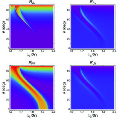
In order to set a baseline for discussion, Fig. 2 displays all four reflectances as functions of the normalized wavelength and the angle of incidence , when and the SCM is of the regular (i.e., non-hyperbolic) type: , , and . A sigmoid ridge of high values of is evident in the figure. The limits (4) with replaced by , , are satisfied by this ridge. For , is negligible in that portion of the - plane which is occupied by the high- ridge; additionally, both cross-polarized reflectances are very small. The huge excess of over accompanied by very small values of the two other reflectances is the chief manifestation of the circular Bragg phenomenon.
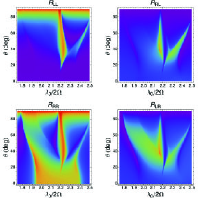
When the sign of was altered from positive to negative, the SCM of Fig. 2 became hyperbolic and the sigmoid high- ridge of that figure disappeared. However, a search with somewhat higher values of soon revealed a portion of the - plane in which (i) exceeds by a large margin and (ii) the excess of over is even greater, with very close to zero. In Fig. 3, circular-polarization-selective reflection is clearly evident for and as well as in the upper left neighborhood of that rectangular zone, for the hyperbolic SCM.
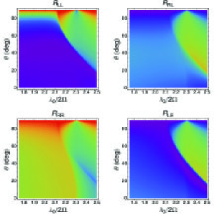
Next, for the computation of the reflectances presented in Fig. 4 as functions of and , the following parameters were used: , , , and . Thus two of the three eigenvalues of now have negative real parts. Circular-polarization-selective reflection with almost equal to zero is evident in Fig. 4 for and as well as on the outskirts of this rectangular zone in the - plane.
The exhibition of the circular Bragg phenomenon by a regular SCM for fixed values of and is delineated by the expression (4). One just has to ensure the appropriate choices of and , the correct choice of the latter parameter being determined by the correct choices of , , and . If all three of the eigenvalues of are fixed as well, then an appropriate value of and must be found. But no physical value of may emerge. Therefore, the exhibition of circular-polarization-selective reflection by hyperbolic SCMs was investigated in the - plane for fixed values of , , , and .
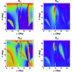
Figure 5 shows all four reflectances computed as functions of and , when , , , and . Thus, only one of the three eigenvalues of has a negative real part. At least four distinct zones of high values of accompanied by almost-zero values of and very low values of both cross-polarized reflectances can be identified in this figure.
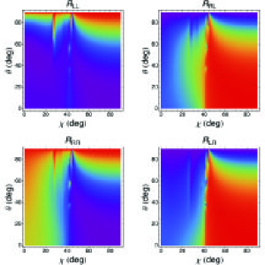
Similar data computed for , , and are displayed in Fig. 6. Now, two of the three eigenvalues of have negative real parts. Circular-polarization-selective reflection with and very low values of and is evident for and .
To conclude, the concept of hyperbolic structurally chiral materials was introduced in this communication. The hyperbolicity was found to significantly alter—but not eliminate—the exhibition of the circular Bragg phenomenon, which has long been known to be the distinctive signature of non-hyperbolic SCMs such as cholesteric liquid crystals [6] and chiral sculptured thin films [8]. Although practical realization of hyperbolic SCMs has yet to occur, physical vapor deposition offers suitable techniques to fabricate these materials.
Acknowledgment. The National Taipei University of Technology is thanked by the author for an honorary international chair professorship. The Charles Godfrey Binder Endowment at Penn State is thanked for partial support of the author’s research activities.
References
- [1] S. Chandrasekhar, Liquid Crystals, 2nd ed., Cambridge University Press, Cambridge, United Kingdom (1992).
- [2] P. G. de Gennes and J. A. Prost, The Physics of Liquid Crystals, 2nd ed., Clarendon Press, Oxford, United Kingdom (1993).
- [3] N. O. Young and J. Kowal, “Optically active fluorite films,” Nature 183(4654), 104–105 (1959), http://dx.doi.org/10.1038/183104a0.
- [4] A. Lakhtakia and R. Messier, Sculptured Thin Films: Nanoengineered Morphology and Optics, SPIE Press, Bellingham, WA, USA (2005), Chap. 9.
- [5] H. Lütkepohl, Handbook of Matrices, Wiley, Chicester, United Kingdom (1996), Chap. 9.
- [6] J. L. Fergason, “Cholesteric structure—I Optical properties,” Molec. Cryst. 1(2), 293–307 (1966), http://dx.doi.org/10.1080/15421406608083274.
- [7] W. D. St. John, W. J. Fritz, Z. J. Lu, and D.-K. Yang, “Bragg reflection from cholesteric liquid crystals,” Phys. Rev. E 51(2), 1191–1198 (1995), http://dx.doi.org/10.1103/PhysRevE.51.1191.
- [8] Q. Wu, I. J. Hodgkinson, and A. Lakhtakia, “Circular polarization filters made of chiral sculptured thin films: experimental and simulation results,” Opt. Eng. 39(7), 1863–1868 (2000), http://dx.doi.org/10.1117/1.602570.
- [9] I. J. Hodgkinson, Q. Wu, K. E. Thorn, A. Lakhtakia, and M. W. McCall, “Spacerless circular-polarization spectral-hole filters using chiral sculptured thin films: theory and experiment,” Opt. Commun. 184(1-4), 57–66 (2000), http://dx.doi.org/10.1016/S0030-4018(00)00935-4.
- [10] D. R. Smith, P. Kolinko, and D. Schurig, “Negative refraction in indefinite media,” J. Opt. Soc. Am. B 21, 1032–1043 (2004), http://dx.doi.org/10.1364/JOSAB.21.001032.
- [11] R. A. Depine, M. E. Inchaussandague, and A. Lakhtakia, “Classification of dispersion equations for homogeneous, dielectric-magnetic, uniaxial materials,” J. Opt. Soc. Am. A 23(4), 949–955 (2005), http://dx.doi.org/10.1364/JOSAA.23.000949.
- [12] J. Sun, J. Zhou, B. Li, and F. Kang, “Indefinite permittivity and negative refraction in natural material: graphite,” Appl. Phys. Lett. 98(10), 101901 (2011), http://dx.doi.org/10.1063/1.3562033.
- [13] X. Gerbaux, M. Tazawa, and A. Hadni, “Far IR transmission measurements on triglycine sulphate (TGS), at 5K,” Ferroelectrics 215(1), 47–63 (1998), http://dx.doi.org/10.1080/00150199808229549.
- [14] L. V. Alekseyev, V. A. Podolskiy, and E. E. Narimanov, “Homogeneous hyperbolic systems for terahertz and far-infrared frequencies,” Adv. OptoElectron. 2012, 267564 (2000), http://dx.doi.org/10.1155/2012/267564.
- [15] M. Schubert, T. E. Tiwald, and C. M. Herzinger, “Infrared dielectric anisotropy and phonon modes of sapphire,” Phys. Rev. B 61(12), 8187–8201 (2000), http://dx.doi.org/10.1103/PhysRevB.61.8187.
- [16] J. Kanungo and J. Schilling, “Experimental determination of the principal dielectric functions in silver nanowire metamaterials,” Appl. Phys. Lett. 97(2), 021903 (2010), http://dx.doi.org/10.1063/1.3462311.
- [17] O. Kidwai, S. V. Zhukovsky, and J. E. Sipe, “Effective-medium approach to planar multilayer hyperbolic metamaterials: strengths and limitations,” Phys. Rev. A 85(5), 053842 (2012), http://dx.doi.org/10.1103/PhysRevA.85.053842.
- [18] C. L. Cortes, W. Newman, S. Molesky, and Z. Jacob, “Quantum nanophotonics using hyperbolic metamaterials,” J. Opt. (UK) 14(6), 063001 (2012), http://dx.doi.org/10.1088/2040-8978/14/6/063001.
- [19] M. A. K. Othman, C. Guclu, and F. Capolino, “Graphene-dielectric composite metamaterials: evolution from elliptic to hyperbolic wavevector dispersion and the transverse epsilon-near-zero condition,” J. Nanophotonics 7, 073089 (2013), http://dx.doi.org/10.1117/1.JNP.7.073089.
- [20] X. Ni, S. Ishii, M. D. Thoreson, V. M. Shalaev, S. Han, S. Lee, and A. V. Kildishev, “Loss-compensated and active hyperbolic metamaterials,” Opt. Express 19(25), 25242–25254 (2011), http://dx.doi.org/10.1364/OE.19.025242.
- [21] T. G. Mackay and A. Lakhtakia, “On the application of homogenization formalisms to active dielectric composite materials,” Opt. Commun. 282(13), 2470–2475 (2009), http://dx.doi.org/10.1016/j.optcom.2009.03.035.
- [22] H. J. Gerritsen and R. T. Yamaguchi, “A microwave analog of optical rotation in cholesteric liquid crystals,” Am. J. Phys. 39(8), 920–923 (1971), http://dx.doi.org/10.1119/1.1986325.
- [23] I. J. Hodgkinson, A. Lakhtakia, Q. h. Wu, L. De Silva, and M. W. McCall, “Ambichiral, equichiral and finely chiral layered structures,” Opt. Commun. 239(4-6), 353–358 (2004), http://dx.doi.org/10.1016/j.optcom.2004.06.005.
- [24] R. J. Martín-Palma and A. Lakhtakia, Nanotechnology: A Crash Course, SPIE Press, Bellingham, WA, USA (2010), Chap. 4.
- [25] R. W. P. King and S. S. Sandler, “The electromagnetic field of a vertical electric dipole in the presence of a three-layered region,” Radio Sci. 29(1), 97–113 (1994), http://dx.doi.org/10.1029/93RS02662.
- [26] C. F. Bohren, X. Xiao, and A. Lakhtakia, “The missing ingredient in effective-medium theories: standard deviations,” J. Modern Opt. 59(15), 1312–1315 (2012), http://dx.doi.org/10.1080/09500340.2012.713521.
- [27] A. Lakhtakia, “Reflection of an obliquely incident plane wave by a half space filled by a helicoidal bianisotropic medium,” Phys. Lett. A 374, 3887–3894 (2010), http://dx.doi.org/10.1016/j.physleta.2010.07.047.