Beat note stabilization of mode-locked lasers
for quantum information processing
Abstract
We stabilize a chosen radiofrequency beat note between two optical fields derived from the same mode-locked laser pulse train, in order to coherently manipulate quantum information. This scheme does not require access or active stabilization of the laser repetition rate. We implement and characterize this external lock, in the context of two-photon stimulated Raman transitions between the hyperfine ground states of trapped quantum bits.
The field of quantum information science holds great promise to revolutionize a wide range of applications, from computing and communication Nielsen and Chuang (2000) to the simulation of complex quantum phenomena that cannot be modeled classically Feynman (1982). Quantum information is usually represented by distinct energy levels within quantum systems such as atoms or isolated solid state systems, with energy separations in the microwave or optical domain. Such qubit states can typically be manipulated with external fields such as microwaves or optical fields whose frequency matches the qubit splitting, given appropriate couplings between the states. Mode-locked lasers are versatile instruments for this purpose with their broadband optical spectra that feature both radiofrequency (rf) and microwave structure. Such lasers have been used to control atomic Hayes et al. (2010), molecular Pe’er et al. (2007), and solid-state quantum systems Greve et al. (2013). In this note, we describe a simple technique to phase-lock these optical sources in order to manipulate and control generic qubit systems Ladd et al. (2010).
Mode-locked lasers can be used to produce a broadband optical frequency comb with overall bandwidth ranging from GHz – THz with comb teeth that are spaced by the repetition rate of the laser, typically in the range GHz. In order to bridge the frequency gap of a particular qubit, the qubit splitting is matched to be near an integral multiple of the repetition rate, and fine tuning is accomplished with additional optical modulators Hayes et al. (2010). In order to retain long term coherence in the quantum system, the relevant optical frequency difference from the laser source must be stable. This can be accomplished by directly locking the laser repetition rate by controlling the laser cavity spacing. Here we describe a more useful technique to stabilize the beat note using acousto-optic modulators (AOMs) outside the laser cavity. This technique provides higher lock bandwidths without requiring invasive access to the laser cavity.
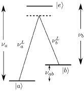
We consider the control of a generic three level ‘’ quantum system, shown in Fig. 1. An electromagnetic field couples two low-energy (qubit) states off-resonantly through a higher excited state, and the latter can be adiabatically eliminated in the process Wu (1996). For example, in Fig. 1, two laser beams with frequencies and couple the states and off-resonantly to the excited state , which is separated from the low energy states by frequencies and respectively. Stimulated Raman transitions will then be driven between the states and when the frequency difference between the beams is tuned close to the qubit resonance frequency .
One convenient way to generate the requisite frequency difference is to split the light from a laser source into two paths, frequency shift the beam in one of the paths, and recombine them at the position of the qubit. This eliminates sensitivity to common-mode fluctuations in the frequency of the laser Thomas et al. (1982). If the transition frequency GHz, an AOM may be used to generate the frequency shift. For larger shifts up to GHz, an electro-optic modulator can be used, although the resulting optical beat notes can be suppressed due to the phase-shifted pattern of the frequency-modulation sidebands Lee et al. (2003). Mode-locked lasers produce amplitude-modulated (AM) sidebands that do not suffer from this phase problem, and provide the best solution for generating the sidebands for this purpose. Bandwidths of mode-locked lasers are typically large enough to address frequency splittings THz, and combined with modest frequency shifts from an AOM, they can be used to reach arbitrary frequency splittings within this bandwidth.
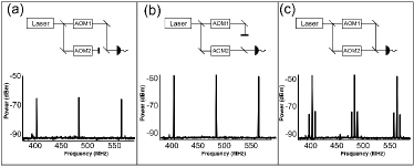
In order to tune the frequency of the fields that drive transitions in the qubit, the beam from a mode-locked laser is split into two paths with frequency shifts and impressed in the respective arms, and then recombined at the qubit. The relative path lengths of the arms must be set to ensure simultaneous pulse overlap on the qubit, but they need not be long-term stable at optical wavelength scales. Figure 2 shows the resulting rf spectrum of the beams as measured by a fast photodiode, displaying the rf comb teeth separated by the laser repetition rate for each individual beam and then with additional beat notes separated by for the combined beams, where . We control the position of these extra sidebands by adjusting the relative shift of the paths to bring the beat note between a comb tooth and a sideband on resonance with an atomic transition: is set to , where is some integer and is within the bandwidth of the frequency comb. Note for transitions as in Fig. 1, the laser carrier-envelope phase need not be stabilized Pe’er et al. (2007), although this too can be accomplished in a similar manner as reported here Koke et al. (2010).
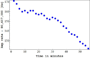
Driving the qubit requires optical coherence between the various comb teeth over the ms or faster time scale of the qubit manipulation, which is easy to achieve for typical transform-limited mode-locked laser sources Hayes et al. (2010). However, as the laser repetition rate drifts [] due to thermal or other mechanical strains in the laser cavity length (Fig. 3), the applied sideband frequency and hence the qubit drive will also drift from resonance. Stabilizing the repetition rate by directly feeding back an error signal to the laser cavity length may be difficult when the laser cavity is not easily accessible, as in the case of a hermetically sealed or fiber laser. Furthermore, such a lock will have limited bandwidth, as the acquisition time for measuring the laser repetition rate and the delay in modulating the laser cavity length with a mechanical transducer may be longer than the characteristic time over which the laser cavity fluctuates. As an example, the hyperfine transition in the electronic ground state of (at 12.642819 GHz) is near the comb tooth of a mode-locked frequency tripled Nd:YVO4 laser at MHz. To stabilize this high order sideband within a fraction of 1 KHz, we must measure to better than a few Hz, which corresponds to an integration time of longer than 1 s. We have found that this type of slow lock is insufficient for achieving high-fidelity qubit transitions with the frequency comb.
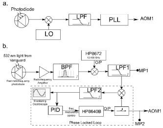
Instead, we continuously monitor the laser repetition rate by beating the photodiode signal at with a frequency-stabilized local oscillator at frequency , as shown in fig. 4(a). The beat note is sent through a filter which passes the lower frequency component of the beat signal at (we assume that ). We can then electronically amplify this error signal and use it to drive one of the AOMs at frequency , so that fluctuations in the repetition rate are canceled and the sideband frequency appears at , which is independent of time. Note that the fluctuations do not cancel for any other comb tooth or its sidebands in general.
In practice, this error signal may have significant broadband noise from the amplifier circuit, causing fidelity errors in the qubit operation. If the fractional spectral noise density of optical power in the error signal beam is [dB/Hz] and assumed to be flat, the broadband Rabi frequency noise density will be since the nominal Rabi frequency is a product of the optical fields of the two beams and only one arm has this added noise. The resulting probability of error in state evolution will scale as , where is the total evolution time of the quantum process. For a Rabi frequency kHz and an evolution time of ms, in order to keep we must have a fractional noise level of dB/Hz, which is difficult with realistic amplifiers.
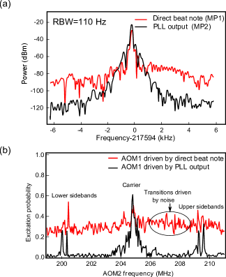
However, it is possible to attain such noise floors by feeding the beat note error signal into a phase locked loop (PLL) configuration with a separate low-noise rf oscillator, and using its output to drive the modulator (AOM1). Beyond the bandwidth of the low-pass filter used in the PLL, the noise profile then takes the characteristics of the oscillator. Fig. 5(a) shows the measured spectrum of the error signal that drives the modulator AOM1 with and without the PLL, with a reduction of the noise floor by dB with the PLL method. In fig. 5(b) we show the observed Raman spectrum of a single trapped ion taken by scanning the frequency of the beat note through AOM2, when the qubit is excited at a pulse duration of . The white noise present when directly driving AOM1 with the error signal produces unwanted Raman transitions for a range of frequencies of AOM2, thus providing a non-zero background in the observed spectrum, as shown in the red trace. On the other hand, when we drive AOM1 with the output of the PLL, this background vanishes, as seen in the black trace.
To characterize the stability of the beat note frequency, we compare it to the ‘clock’ hyperfine qubit by Ramsey interferometric measurements. With the lock engaged we measure a coherence time of order s, consistent with known external sources of noise such as magnetic field noise Olmschenk et al. (2007). With the repetition rate lock disengaged, the coherence time drops to ms. Because the lock continuously tracks the difference frequency between a laser beat note and a microwave standard, the lock speed is limited only by electronic delays and can have a bandwidth as high as 100 MHz, while also tracking long term drifts without running out of range.
ACKNOWLEDGEMENTS
This work is supported by the DARPA Optical Lattice Emulator Program, the IARPA MQCO Program under ARO contract, the ARO MURI Program on Hybrid Quantum Circuits, and the NSF Physics Frontier Center at JQI.
References
- Nielsen and Chuang (2000) M. A. Nielsen and I. L. Chuang, Quantum Computation and Quantum Information (Cambridge University Press, Cambridge, UK, 2000).
- Feynman (1982) R. Feynman, Int. J. Theor. Phys. 21, 467 (1982).
- Hayes et al. (2010) D. Hayes, D. N. Matsukevich, P. Maunz, D. Hucul, Q. Quraishi, S. Olmschenk, W. Campbell, J. Mizrahi, C. Senko, and C. Monroe, Phys. Rev. Lett. 104, 140501 (2010).
- Pe’er et al. (2007) A. Pe’er, E. A. Shapiro, M. C. Stowe, M. Shapiro, and J. Ye, Phys. Rev. Lett. 98, 113004 (2007).
- Greve et al. (2013) K. D. Greve, D. Press, P. L. McMahon, and Y. Yamamoto, Reports on Progress in Physics 76, 092501 (2013).
- Ladd et al. (2010) T. D. Ladd, F. Jelezko, R. Laflamme, Y. Nakamura, C. Monroe, and J. L. O’Brien, Nature 464, 45 (2010).
- Wu (1996) Y. Wu, Phys. Rev. A 54, 1586 (1996).
- Thomas et al. (1982) J. E. Thomas, P. R. Hemmer, S. Ezekiel, C. C. Leiby, R. H. Picard, and C. R. Willis, Phys. Rev. Lett. 48, 867 (1982).
- Lee et al. (2003) P. J. Lee, B. Blinov, K.-A. Brickman, L. Deslauriers, M. Madsen, R. Miller, D. L. Moehring, D. Stick, and C. Monroe, Opt. Lett. 28, 1582 (2003).
- Koke et al. (2010) S. Koke, C. Grebing, H. Frei, A. Anderson, A. Assion, and G. Steinmeyer, Nature Phot. 4, 462 (2010).
- Olmschenk et al. (2007) S. Olmschenk, K. C. Younge, D. L. Moehring, D. N. Matsukevich, P. Maunz, and C. Monroe, Phys. Rev. A 76, 052314 (2007).