E-mail to: virgilli@fe.infn.it
The LAUE project and its main results
Abstract
We will describe the LAUE project, supported by the Italian Space Agency, whose aim is to demonstrate the capability to build a focusing optics in the hard X-/soft gamma-ray domain (80–600 keV). To show the lens feasibility, the assembling of a Laue lens petal prototype with 20 m focal length is ongoing. Indeed, a feasibility study, within the LAUE project, has demonstrated that a Laue lens made of petals is feasible. Our goal is a lens in the 80-600 keV energy band. In addition to a detailed description of the new LARIX facility, in which the lens is being assembled, we will report the results of the project obtained so far.
keywords:
Laue lenses, focusing telescopes, gamma-rays, Astrophysics.1 INTRODUCTION
Very sensitive observations of celestial hard X–/soft gamma–ray photons (80–100 keV) are of key importance for the knowledge of many physical processes in the Universe[1] . Unfortunately, till now observations beyond 80 keV have been performed with sky direct-viewing instruments the sensitivity of which is background limited and limited is also their angular resolution (about arcmin in the case of INTEGRAL/IBIS mask telescope). To improve flux sensitivity and angular resolution, the use of gamma-ray focusing optics is crucial. The LAUE project, supported by the Italian Space Agency (ASI), is a follow-up of the HAXTEL project and is devoted to create a technology to build a Laue lens with long focal length (20–100 m) able to focus photons in the 80–600 keV energy range. In the HAXTEL project, two prototypes of Laue lens with 6 m focal length (FL) have been built using flat mosaic copper crystals. The experience acquired from the HAXTEL project has shown that, for FL longer than 10–15 m a new assembling technique is needed.
Moreover, a new generation of crystals must be developed for Laue lenses, given that the Point Spread Function (PSF) of a flat crystal is related to the size of the crystal itself. Flat crystals are also limited in terms of diffraction efficiency given that their theoretical limit is the 50%. In the last years, new technologies have been developed to obtain bent crystals, whose properties surpass those shown by flat mosaic crystals in terms of efficiency and focusing capability.
In the LAUE project, an industrial study has been performed to check the feasibility of a modular lens. An entire lens is made of petals. Each petal can be made of sub-petals (or petal sectors). The crystals tiles are accommodated in the petal sectors (see Fig. 1).
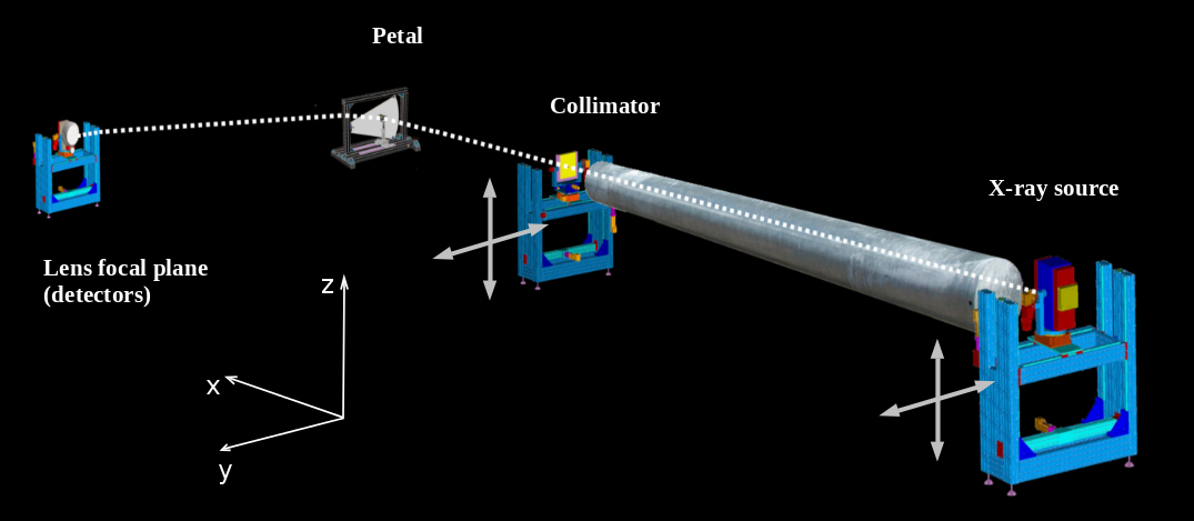
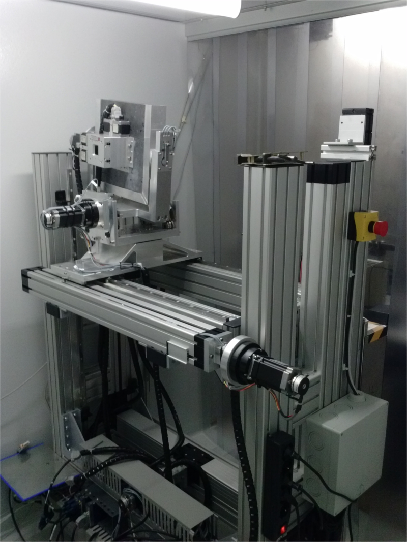
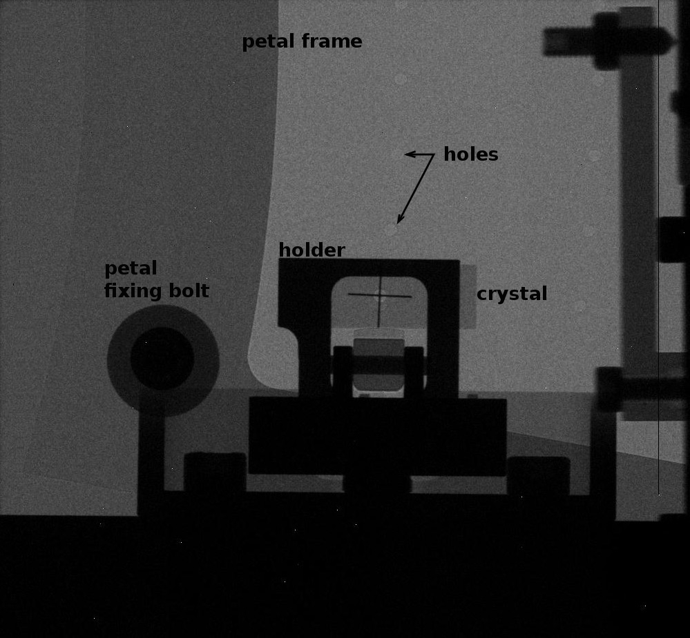
One of these petals is being built as a demonstration of the project success. The adopted technology consists in the positioning of the crystal tiles on the lens frame under the control of a gamma-ray beam. The lens frame is kept fixed during the entire lens assembling process, while the gamma-ray source and a mechanical collimator, which includes a slit with variable aperture, are moved together along the Y and Z axes to simulate a parallel beam. Each diffracting crystal is correctly translated and oriented in order to focus the beam photons on the lens focal plane. The final crystal tile position is then glued upon the lens frame. The main elements of the project are summarised in Fig. 2 where also the reference axes are shown to clarify the description of each component and its possible motion.
2 The LARIX facility
The entire apparatus for both assembling and testing the lens is installed in the LArge Italian X-ray laboratories (LARIX) located at the Physics and Earth Science Department of the University of Ferrara. The laboratories include an experimental room (LARIX A) with a 12 m long facility and a 100 m long tunnel. The facility in LARIX A has been successfully used for calibrating JEM X aboard the INTEGRAL satellite [2] , and building and testing two prototypes of Laue lenses with 6 m focal length made of 20 copper flat mosaic crystals [3, 4] .
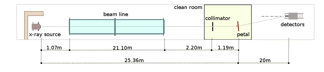
The same facility is supporting the LAUE project and is used for a preliminary qualification of each crystal tile in terms of reflectivity and curvature radius before to be used for the LAUE project. The 100 m long tunnel is instead the ideal place for the LAUE project. It allows to obtain a small divergence of the beam impinging on each crystal and to build Laue lenses with long focal length. In Figure 3 it is shown a sketch of the tunnel and the relative distances between the installed sub-systems.
The complete apparatus mounted in the LARIX facility consists of the following sub-systems that will be in detail described in the next subsections.
-
•
X-ray source;
-
•
Beam-line with vacuum environment;
-
•
Clean room with thermal and humidity control;
-
•
Adjustable mechanical slit;
-
•
Hexapod positioning device and crystal holder;
-
•
Petal frame;
-
•
Focal plane detectors;
-
•
Translation and rotation systems for the motion of each subsystem (source, collimator slit, crystals);
-
•
Rail for translating the focal plane detectors along the lens axis;
-
•
Hardware and software needed for the remote control (Ground Support Equipment, GSE).
2.1 The X-ray sources
The tunnel of the LARIX facility is equipped with two X– and gamma–ray generators. The first is a portable betatron that provides a photon source with maximum energy of 2.5 MeV. Thanks to the extremely broad energy band, the betatron could be exploited for assembling and testing Laue lenses with nominal passband of 80–600 keV, which is our final astrophysical goal.
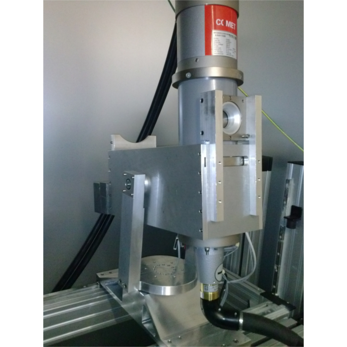
The second generator makes use of a traditional X–ray tube (provided by Bosello Technology) with a fine focus of 0.3 0.4 mm2, a maximum voltage of 320 kV, and a maximum power of 1800 W(Fig. 4 left). The advantage of this gamma–ray generator is that is much brighter than the betatron. Thus, to speed up the assembling phase of the lens petal prototype foreseen within the LAUE project we have adopted the latter generator. This choice has limited the upper threshold of energy band of the lens petal prototype to keV.
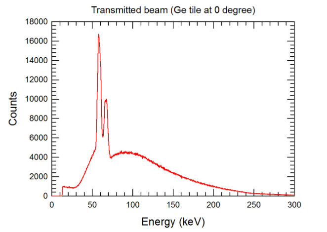
In table 1 we report the main properties of the adopted X-ray generator. A typical beam measured by the spectrometer coming from the source and absorbed by a 2 mm thick Germanium crystal is shown in Fig. 5.
A 20 mm thick Tungsten shield with a 3 mm diameter hole has been installed in front of the aperture of the X-ray tube to reduce the X-ray beam. A further collimation is obtained with a drilled (1 mm diameter) 50 mm thick lead collimator (Fig. 4 right). Source plus collimators can be moved on the plane Y-Z (X is the beam axis). Thanks to the overall collimation, the background level at the lens focus has been highly reduced.
| Nominal Tube Voltage (kV) | 320 |
|---|---|
| Maximum power (W) | 800 / 1800 |
| Focal spot size (mm) | dsmall = 0.4 |
| dbig = 1.0 | |
| Inherent filtration | 3 mm Be |
| Target material | W |
| Cooling medium | Oil |
| Weight (kg) | 40 |
2.2 Beam-line and clean room
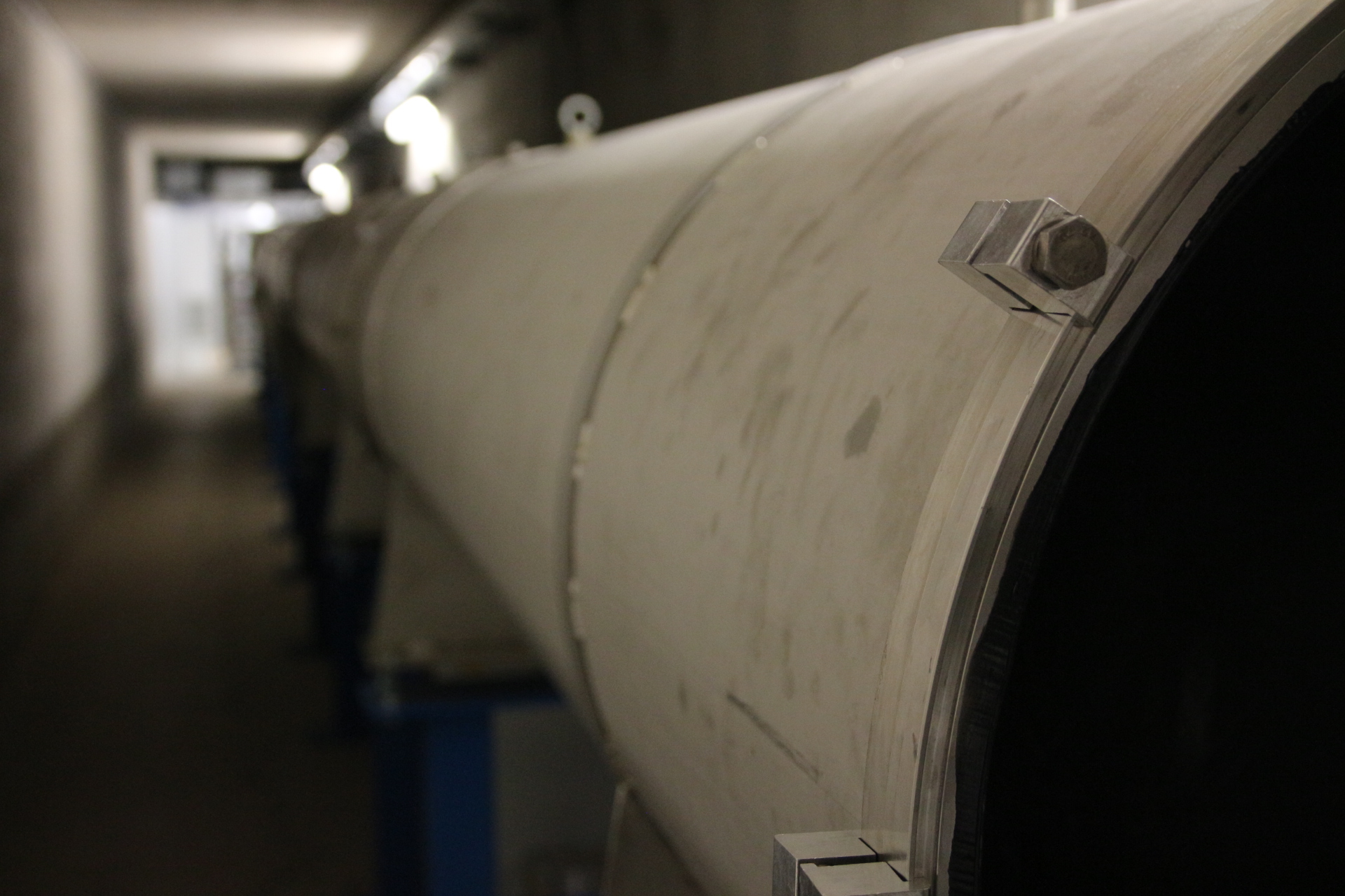
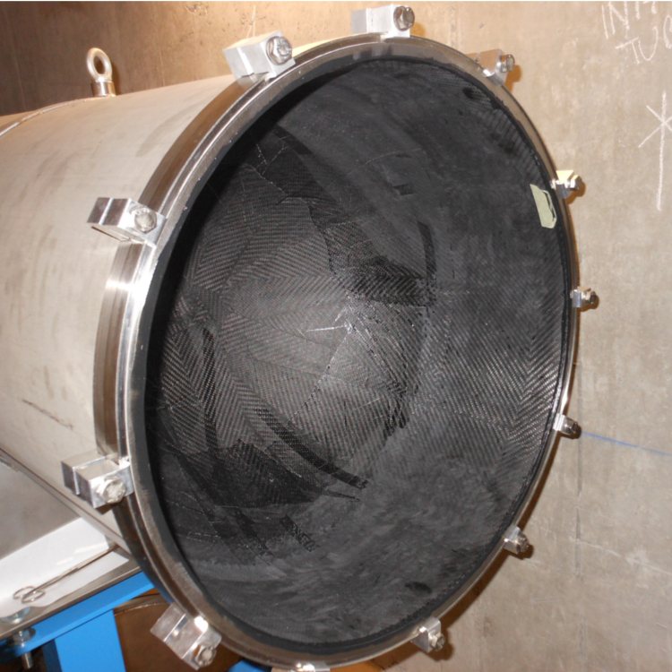
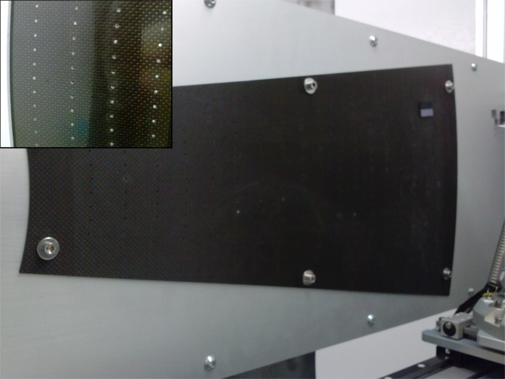
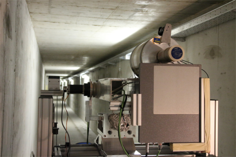
After the collimated photon beam pass through a 21 m long under–vacuum beamline to avoid absorption and scattering of the generated beam off air. The beamline is made of a set of 7 modules. Each module is a tube of stainless steel with a length of 3 m. The vacuum environment is guaranteed by three vacuum pumps that keep stable the pressure below 1 mbar. The pressure read out control is performed with a set of probes, one for each pump. The X–ray entrance and exit windows of the beamline are made of carbon fiber 3 mm thick which guarantee a gamma–ray transparency % @ 100 keV. Figure 6 shows a detail of the beam-line and one of the carbon fiber entrance windows.
Given the requested positioning accuracy of the single crystal tiles on the lens petal frame, lens petal prototype is assembled in a low-laminar-flow clean room (dimensions 2 8 m2, class 105, US FED STD 209E Clean room Standards). It is equipped with a thermal control (within accuracy) and an hygrometric control (relative humidity = 50% within an error of 10%).
2.3 Mechanical and motorized collimator
After the beam-line the beam impinges on a collimator equipped with a slit with variable aperture. It has to be moved together with the X-ray generator along the Y-Z axes to artificially reproduce the presence of a source coming from the infinity. Thus X-ray beam so obtained is always parallel to itself and to the lens axis while it is impinging on every crystal tile during the crystal assembling phase. Thus the collimator is equipped with motors that can translate it in the X-Y plane and it is provided with three motors to rotate the slit around the X, Y and Z axes.
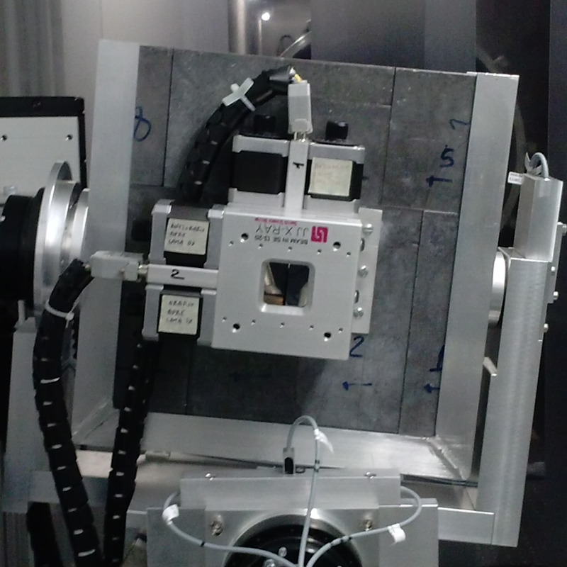
The collimator has also another important role. It has to shield the beam coming from the source, except that around the beam axis. The shielding is achieved by a lead panel with 200 200 mm2 cross section and 50 mm thick. In the center of the panel it has a 30 30 mm2 aperture window. In correspondence of this window a motorized slit with variable aperture is located. The variable aperture is obtained by means of four crossed and independent 20 mm thick blades made of Tungsten Carbide (density 15.6 g/cm3, 1 % transparency @ 600 keV). In Fig. 7 left it is visible the collimator slit and its carriage while a detail showing the slit located on the 200 200 mm2 lead screen is given in Fig. 7 right.
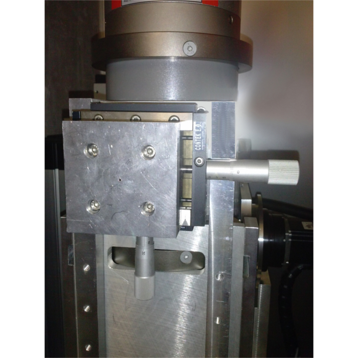
2.4 The hexapod system
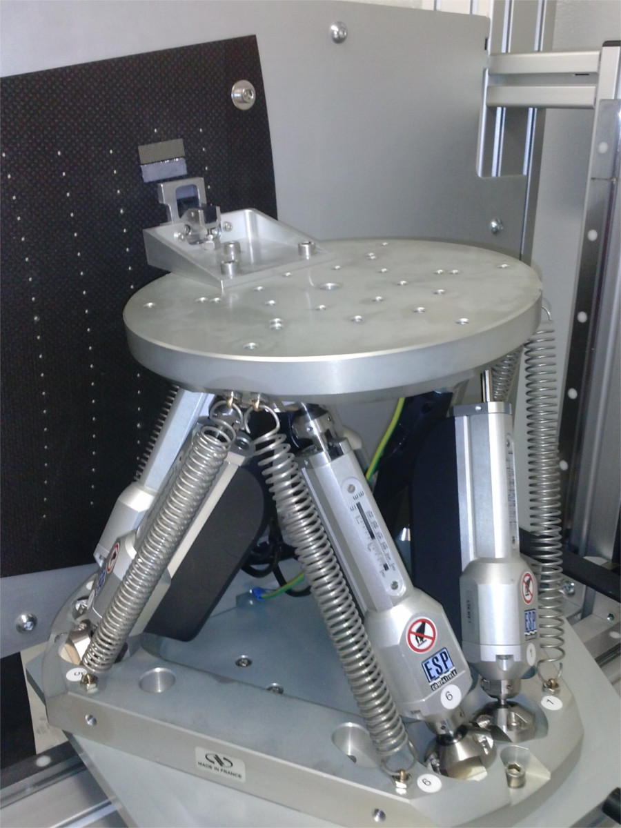
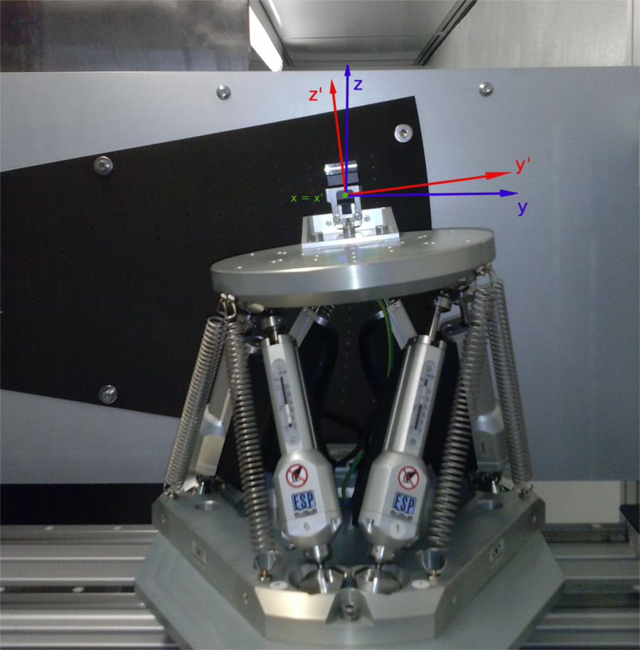
The orientation and the positioning of each crystal on the carbon fiber petal frame is performed with a 6-axis hexapod system (Fig. 8). The rotation and the linear motion uncertainties are 1 arcsecond and 1 m, respectively. While the coarse translations along the Y and Z axis are provided by the carriage, the hexapod is mainly used for the three rotations. The first is the rotation around the beam axis (X) to place each crystal at the nominal position. The other two rotations around Z’ and Y’ axis of the crystal rest frame), which in general do not coincide with the laboratory reference system Y and Z, allow to find the proper diffraction angle. The hexapod is also provided with a further axis (along X) to approach (remove) the crystal to (from) the petal frame.
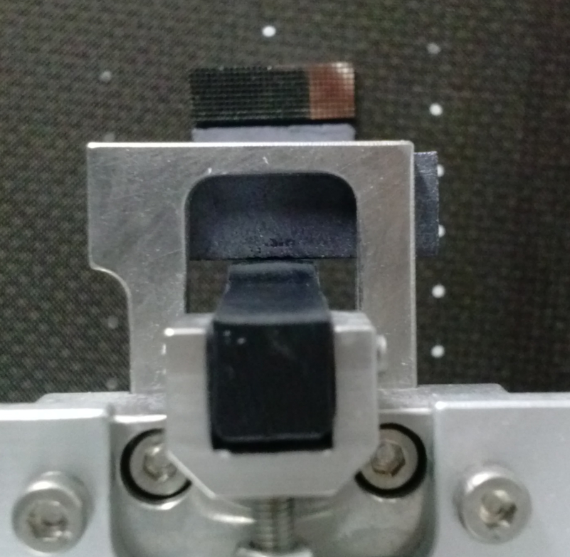
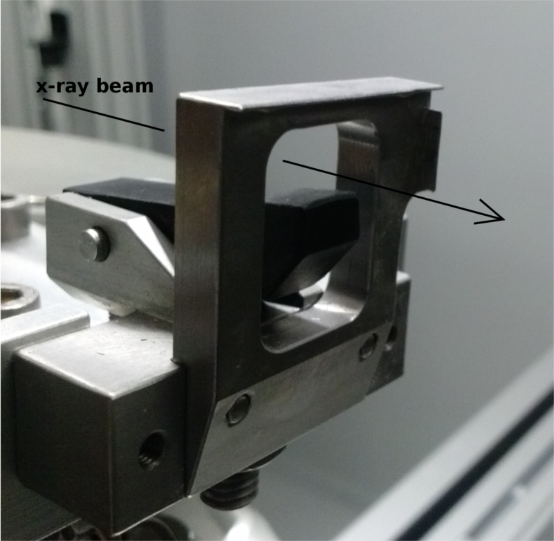
The crystal tile holder has been developed in order to firmly hold the tile and, at the same time, to leave free the front and back main faces of the crystal, where the incident beam arrives and the diffracted beam is produced. In order to fill as much as possible the lens frame with crystals, the left side of the tile is free (see Fig. 9).
2.5 The petal frame
The lens petal frame holds the crystal tiles. The crystals are properly aligned and placed in the correct position, then glued and fixed on the petal frame. Its total thickness (2.3 mm) is realized with a superposition of 10 layers of carbon fiber. Assuming a an inter-distance between contiguous crystals of 0.2 mm, we have designed the cell in which each crystal has to be positioned on the frame (see Fig. 10). In the center of each cell, the frame is drilled, and through the hole the resin is injected for fixing the crystals to the frame. From the location of the cell and the assumed focal length of 20 m, the expected energy in correspondence of the center of each cell is computed.
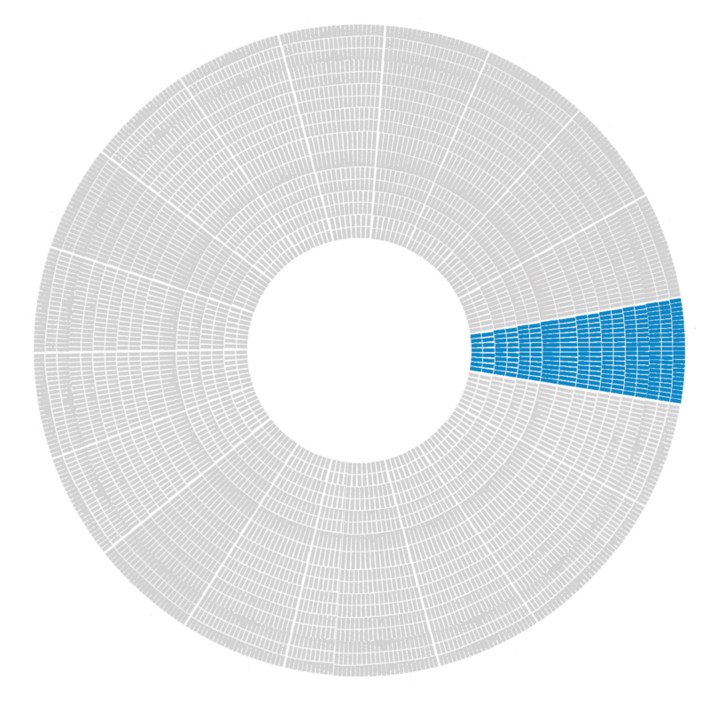
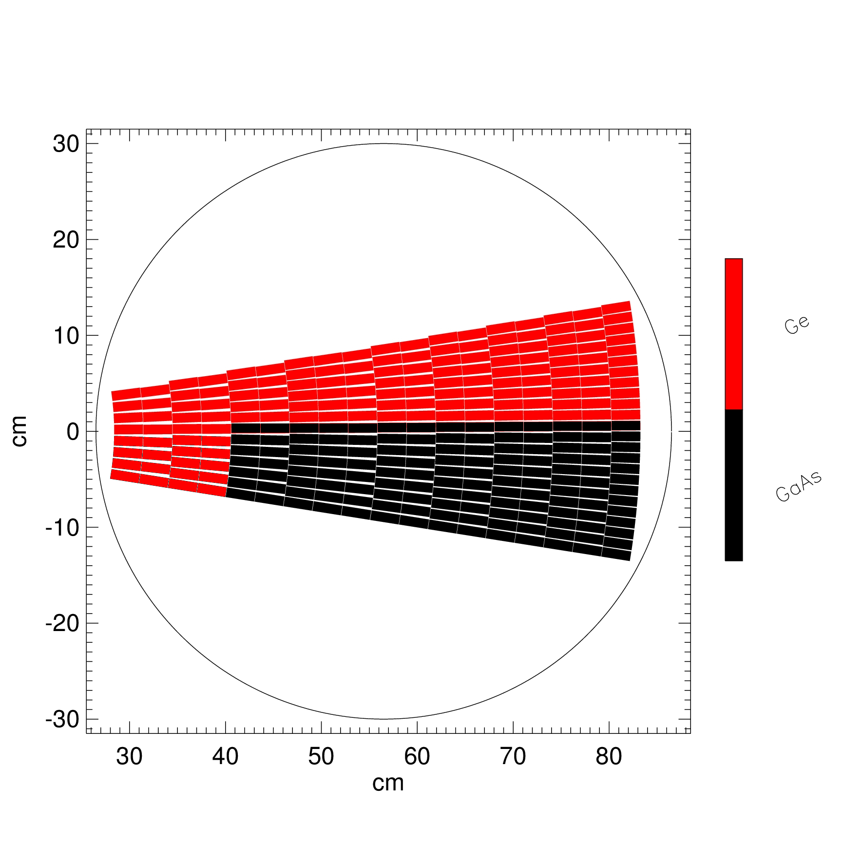
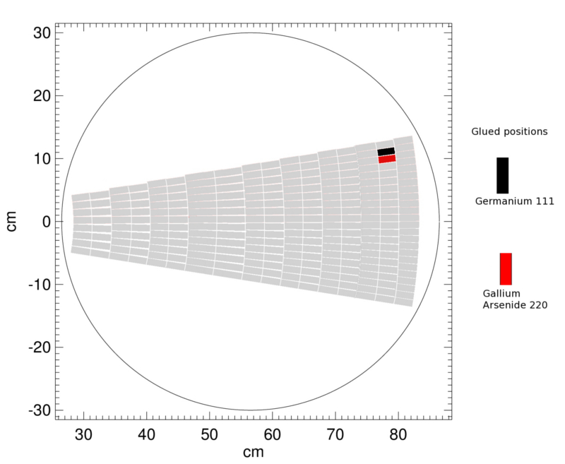
In Table 2, the properties of the lens petal prototype, which is being assembled, are reported. The energy passband is defined by the inner and outer radius of the lens petal. For the designed petal, these values are those allowed by the beamline diameter within which the petal has to be inscribed (see Fig. 11). The lens passband is also driven by the X-ray source maximum energy (about 300 keV). The upper part of the petal (red portion in Fig. 11) will be filled with Ge (111) tiles while the bottom part will be filled with GaAs (220) tiles. Being the atomic d-spacing different for the two specimen, the relative passband is different. In the former case the diffracted energy band is 90 – 267 keV while for the latter is 148 – 304 keV.
| GaAs(220) sector | Ge(111) sector | Entire petal | |
|---|---|---|---|
| Focal length | 20 m | 20 m | 20 m |
| Energy range | 148 – 304 keV | 90 – 267 keV | 90 – 304 keV |
| No. of rings | 14 | 18 | 18 |
| Minimum radius | 40.66 cm | 28.40 cm | 28.40 cm |
| Maximum radius | 83.47 cm | 83.47 cm | 83.47 cm |
| No. of crystal tiles | 119 | 155 | 274 |
| Crystal dimension (mma) | 30 10 2 | 30 10 2 | 30 10 2 |
| Crystal mass (total) | 2.5 g 119 = 297.5 g | 2.07 g 155 = 320.85 g | 618.35 g |
a radial dimension, tangential dimension, thickness
2.6 The focal plane detectors
The measurement of the diffracted signal produced by each crystal is performed by means of two focal plane detectors. Both are placed on a carriage at the focal distance of 20 m from the petal frame. The carriage can be moved along the lens axis by means of a 15 m long rail. The detectors are shown in Fig. 12.
The X-ray imaging detector has a spatial resolution of 200 m. The main properties of the imager are summarised in Tab. 3. The imager is a flat panel based on a CsI scintillator (0.8 mm thick) that converts the X and gamma-rays into optical light that is afterwards converted into an electric signal from an array of photodiodes. The imager allows to detect the space distribution of the photons diffracted by the cross section of each crystal which is irradiated by the incident beam. By means of an IDL code the Y’ and Z’ barycenter coordinates of the diffracted beam are estimated and converted into two rotation angles in order to properly shift the diffracted image barycenter over the reference pixel (the centre of the detector @ px 512-x, 512-y).
| Energy range | 40 keV – 15 MeV |
|---|---|
| Spatial resolution (m) | 200 |
| Active area (cm2) | 20.48 20.48 |
| Active pixel number | 1000 1000 |
The cooled HPGe spectrometer provides the spectrum of the diffracted photons. The spectrometer allows to establish the correct positioning of each crystal on the lens, given that the centre of each crystal has to diffract a well defined energy. The detector also allows to have a control of the direct as well as the transmitted beam through the crystals, to estimate their reflection efficiency. In Table 4 are reported the main parameters of the detector.
| Operational energy range | 3 keV – 1 MeV |
| Energy resolution @ 122 keV | 0.4% |
| Semiconductor material | P-type High-Purity Germanium |
| Dewar capacity | 3 l |
| Be window thickness (mm) | 0.254 |
The detectors are placed on a carriage which allows the motion in the Y-Z plane with an uncertainties of 0.5 mm in each direction. It also permits to select which detector has to be positioned on the focus. In order to allow the measurement of both the direct and the diffracted beam, the spectrometer overhangs the carriage using a counterbalance system. The system holding the detectors can also rotate along the three axes.
2.7 Crystals selection
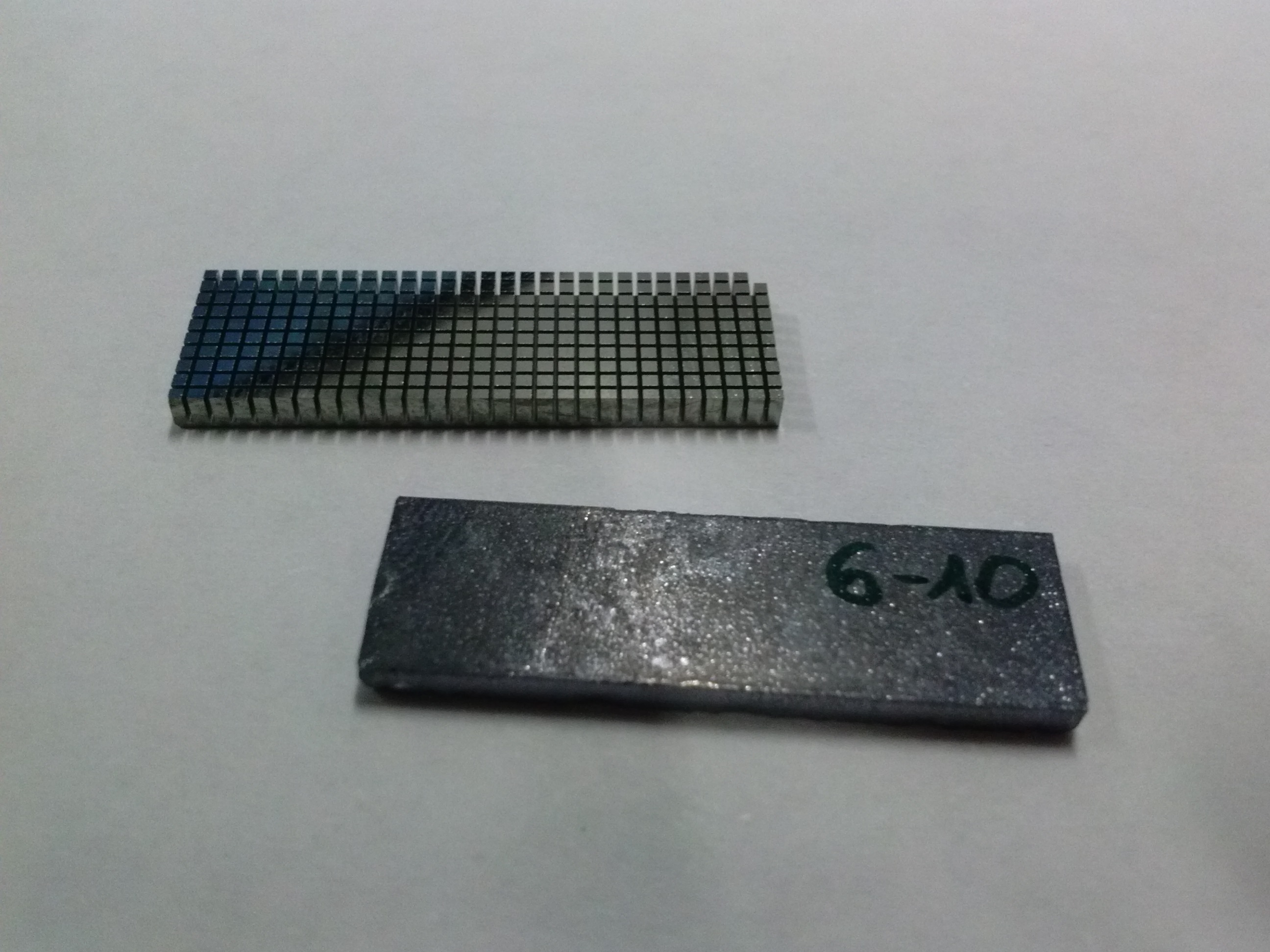
The entire set of tiles used for the experiment is provided by two partners of the project: the Sensor and Semiconductor Laboratory (LSS) of the University of Ferrara and the CNR/IMEM, Parma. The lens petal will be assembled with bent crystal tiles of Germanium (111) (LSS), and Gallium Arsenide (220) (IMEM). The curvature of the Ge (111) tiles are obtained by indentations [5, 6] while the GaAs (220) tiles are bent by surface lapping [7, 8]. For both the specimen an excellent cylindrical or spherical shape with the desired curvature radius can be obtained. The proper curvature of Ge (111) tiles is obtained by finely tuning the parameters of the process like the grooves number, width and depth of indentation, speed of the process [9]. For the GaAs (220) crystals, the lapping exposure time and the fine-grained paper rules the achieved curvature. An estimation of the curvature radius and reflectivity on a sub-set of both materials can be found in 10. Two samples are shown in Fig. 13.
Thanks to the focusing capability of each single tile, it has been possible to choose the crystal cross section to be 30 10 mm2, with the longer size radially placed. The focusing effect will make smaller the point spread function (PSF), according to what has been estimated from the Monte-Carlo simulations, also taking into account the possible misalignments between the tiles, and the curvature uncertainties [11]. A big radial dimension reduces the total number of crystals, minimizing the error budget due to the misalignment of each crystal during the assembling phase. The thickness of the crystal tiles is 2 mm, for each type of crystal material. This is a good compromise between the need of a high reflectivity and the current limitation in the thickness imposed by the bending technology adopted.
2.8 The Ground Support Equipment
Each sub-system is equipped with a set of linear and rotational stages of motion:
-
•
X-ray source: Y and Z traslations, RY and RZ rotations;
-
•
Collimator: Y and Z traslations, RX, RY and RZ rotations;
-
•
Hexapod carriage: Y and Z traslations;
-
•
Hexapod: 6 d.o.f. (X traslation is allowed manually);
-
•
Detectors: Y and Z traslations, RX, RY and RZ rotations (X traslation is allowed manually).
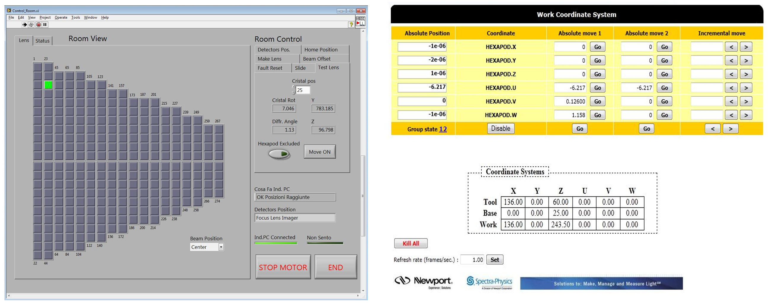
The entire subset of carriages are supposed to be remotely controlled from the control room. For the control of each sub-system a proper LabVIEW code has been developed[12] . The front-end of the remote management suite is shown in Fig. 14(left). During the assembling procedure as well as in the testing phase a selection of the generic light indicators (indicating the crystal to be placed at the corresponding lens position) make the X-ray beam (source and collimator slit) and hexapod/crystal holder automatically moving to the desired position. The control of the hexapod is instead not implemented in the LabVIEW code but is obtained exploiting a dedicated software (Fig. 14(right).
3 Mechanical, optical and gamma-ray alignments of the facility
Each module of the beamline has been placed horizontally and, once mounted, the beamline is fixed. Therefore the other sub-systems of LAUE apparatus must be aligned with respect to the beamline. The petal frame has been placed within the beamline cross section (in the Y-Z plane) and perpendicularly to its direction (X-axis). Also the source and the collimator slit have to move within the same cross section. Finally, the detectors were placed along the X-axis at 20 m from the petal frame. The structure holding the detectors was designed in such a way that both direct and diffracted beam can be observable.
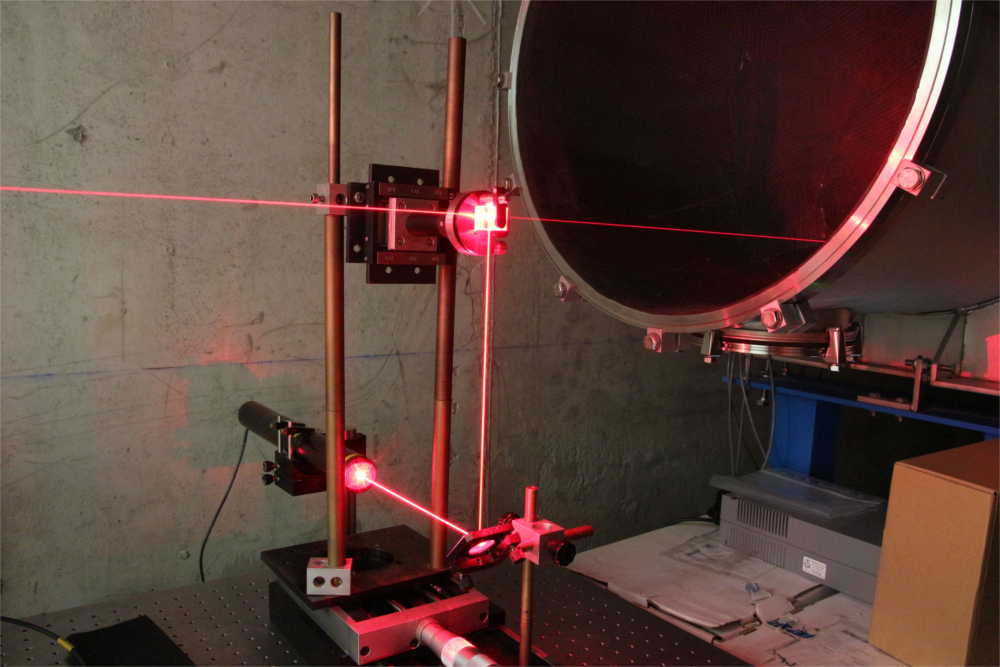
To ensure that all the translations of the source and collimator slit (in the Y-Z plane) are kept parallel, a further optical phase of alignment is adopted. The method is based on a laser, mounted on a optical bench set between the beam-line and the motorized collimator slit, that emits an horizontal light beam. The beam is reflected by a mirror placed at 45o, then is sent to a beam-splitter which splits the beam along opposite directions, one towards the hexapod crystal holder, positioned in a reference lens frame position, through the collimator slit and the other toward the gamma-ray source through the beamline (see Fig. 15). Mirrors placed over the gamma-ray source and over the crystal holder reflect back the two beams. Their superposition in the laser output ensures the correct zero-position for source, collimator, hexapod holding aperture, and the petal reference position.
The optical alignment ensures that the ideal line connecting the source and the collimator slit is parallel to the lens axis. It also guarantees an excellent precision in positioning the center of the gamma–ray imager in correspondence of the lens focus.
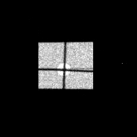
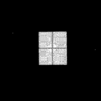
The gamma-ray alignment performs a fine tuning of the previous alignment process. It has been performed using two Tungsten crosses (wire diameter of 200 m) that are placed respectively on the center of a dummy crystal positioned in the crystal holder, and on the aperture center of the slit. The crystal holder, by means of the hexapod, was ina position such that the tungsten cross center was placed in correspondence of the frame hole from which the resin is injected to fix the crystal to the frame. In Fig. 17 we show the crosses before and after the fine tuning.
4 First results
To test the apparatus correct alignment, we performed the crystal orientation of two crystal tiles (one of Ge (111) and the other of GaAs (220)) and then, using the adopted resin, we fixed them to the petal frame. For this test, the two crystals were placed one next the other (cells #24 and #25). In this way we could also check the capability of the hexapod to position them with the required inter-space of 0.2 mm. A sketch of the whole set of crystal cells and those two selected is shown in Fig. 18.
The first results were also exploted to compare expected and measured energy of the diffracted beam in correspondence of chosen crystal cell. We also tested orientation stability of the tiles once the resin had polimerized.
4.1 Spectral results
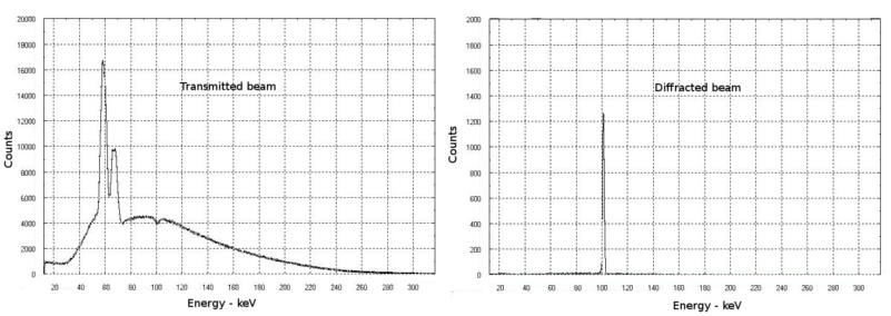
The right orientation of each crystal on the frame is achieved when the beam diffracted by the crystal has a peak energy corresponding to the energy extected for the selected cell. A Ge (111) tile was first tested. Its orientation was that expected for the cell #24 with nominal centroid energy of 96.14 keV.
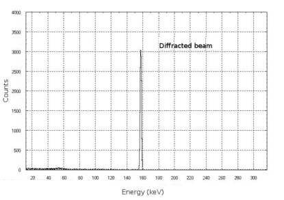
In Fig. 19 left it is shown the transmitted beam through the crystal when the proper diffraction angle was set. A dip at about 100 keV is clearly visible. When the spectrometer is translated to the lens focus, the diffracted spectrum is shown in Fig. 19 right. Similarly, for the GaAs (220) tile placed in the contiguous cell, the spectrum of the diffracted beam is shown in Fig. 20 left.
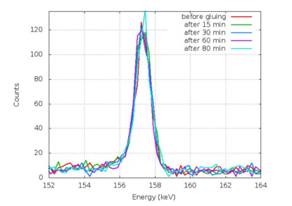
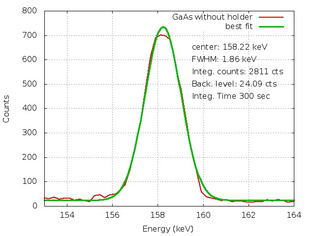
A systematic monitoring of the diffracted beam was performed during the gluing procedure. The spectrum was acquired every 15 minutes after the adhesive injection. Figure 20 right shows that the effect of the glue polimerization does not produce any significant deviation of the centroid energy with respect to the nominal energy expected for the GaAs (220) placed in the cell #25.
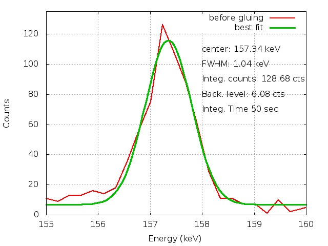
After the glue polimerization, the holder removal is the most critical phase. With the GaAs (220) the centroid energy changed by less than 1 keV, corresponding to less that 20 arcsec. Figure 21 shows the measured spectra before and after the holding removal. The effect is mainly related to the angular tilt between the petal frame and the glued crystal plane. The tilt produces an asymmetric glue distribution over the crystal, giving origin to the observed energy change. The same effect was also observed during the preliminary resin tests in which the orientation of 20 muck-up tiles of 30 10 mm2 cross section was monitored during their polimerization phase. A systematic deviation of 20-30 arcseconds was found. This systematic error is being taken into account during the assembling phase.
4.2 Images of the diffracted beam
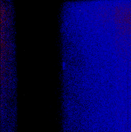
The diffracted beam was also imaged by setting the center of the imager (pixels ) in the nominal lens focus. Due to the beam divergence, it is not possible to hit the entire crystal and observe the complete focusing effect from it. Instead, it is possible to observe the focusing capability when the beam size radiates only the central portion of the tile, making the beam divergence negligible (few arcesconds). Therefore the slit aperture was set to 4 6 mm2 with the smaller size radially.
The focusing effect can be observed in Fig. 22 in which the radial dimension has decreased from 4 mm in correspondence of the crystal to 2 mm at the detector level due to the focusing capability of the crystal. In the orthogonal direction, non focusing effect is expected and, indeed, in this case the beam increases from 6 mm to 12 mm as expected due to the beam divergence.
5 Conclusions
We have described the LAUE project supported by the Italian Space Agency (ASI), in particular the facility developed, in the LARIX laboratory of the University of Ferrara, for assembling and testing Laue lens petals for space applications. The expected accuracy in the lens assembling would allow to build lenses even with very long focal lengths (up to 100 m), a goal never achieved so far. Removing possible systematic effects from the glue polimerization, the goal of 10 arcseconds accuracy appears to be satisfied.
In addition to lens assembling technology the LAUE project has faced the crystal production of proper crystals for Laue lenses. For the first time we have developed and tested bent crystals. They appear the most suitable for their high diffraction efficiency and focusing capability.
As a demonstration of the validity of the adopted technology, a lens petal of 20 m focal length, made of 300 bent crystal tiles of Ge(111) and GaAs(220) is being assembled. We have reported preliminary results on the firsts glued crystals.
References
- [1] Frontera, F., Virgilli, E., Valsan, V., Liccardo, V., Carassiti, V., Caroli, E., Cassase, F., Ferrari, L. R. C., Guidi, V., Pecora, M., S.Mottini, Amati, L., Auricchio, N., Bassani, L., Campana, R., Farinelli, R., Guidorzi, C., Labanti, C., Landi, R., Malizia, A., Orlandini, M., Sguera, V., Stephen, J. B., and Titarchuk, L. G., “Scientific prospects in soft gamma-ray astronomy thanks to the laue project,” SPIE Conference Series 8861- (2013).
- [2] Loffredo, G., Pelliciari, C., Frontera, F., Carassiti, V., Chiozzi, S., Evangelisti, F., Landi, L., Melchiorri, M., Squerzanti, S., Brandt, S., Budtz-Joergensen, C., Laursen, S., Lund, N., Polny, J., and Westergaard, N. J., “X-ray facility for the ground calibration of the x-ray monitor jem-x on board integral,”
- [3] Frontera, F., Loffredo, G., Pisa, A., Nobili, F., Carassiti, V., Evangelisti, F., Landi, L., Squerzanti, S., Caroli, E., Stephen, J. B., Anderson, K. H., Courtois, P., Auricchio, N., Milani, L., and Negri, B., “Focusing of gamma-rays with laue lenses: first results,” in [Society of Photo-Optical Instrumentation Engineers (SPIE) Conference Series ], 7011, SPIE (2008).
- [4] Virgilli, E., Frontera, F., Valsan, V., Liccardo, V., Carassiti, V., Evangelisti, F., and Squerzanti, S., “Laue lenses for hard x-/soft -rays: new prototype results,” in [Society of Photo-Optical Instrumentation Engineers (SPIE) Conference Series ], Society of Photo-Optical Instrumentation Engineers (SPIE) Conference Series 8147 (Sept. 2011).
- [5] Bellucci, V., Camattari, R., Guidi, V., Neri, I., and Barrière, N., “Self-standing bent silicon crystals for very high efficiency laue lens,” Experimental Astronomy 31, 45–58 (2011).
- [6] Guidi, V., Bellucci, V., Camattari, R., and Neri, I., “Curved crystals for high-resolution focusing of X and gamma rays through a Laue lens,” Nuclear Instruments and Methods in Physics Research B 309, 249–253 (Aug. 2013).
- [7] Marchini, L., Ferrari, C., Buffagni, E., and Zappettini, A., “High resolution x-ray characterization of mosaic crystals for hard x- and gamma-ray astronomy,” in [X-ray Astrophysics up to 511 keV ], (Sept. 2011).
- [8] Buffagni, E., Ferrari, C., Rossi, F., Marchini, L., and Zappettini, A., “Preparation of bent crystals as high-efficiency optical elements for hard x-ray astronomy,” Society of Photo-Optical Instrumentation Engineers (SPIE) Conference Serie 8147 (2011).
- [9] Camattari, R., Battelli, A., Bellucci, V., Neri, I., Guidi, V., and Frontera, F., “Fabrication of quasi-mosaic ge crystals for the laue project,” SPIE Conference Series 8861-11 (2013).
- [10] Liccardo, V., Frontera, F., Virgilli, E., Valsan, V., Carassiti, V., Evangelisti, F., Sqerzanti, S., Parise, M., Statera, M., v. Guidi, , Bellucci, V., Camattari, R., Caroli, E., Auricchio, N., Basili, A., Silvestri, S., Stephen, J. B., Cassese, F., Recanatesi, L., Ferrari, C., Zappettini, A., Buffagni, E., Mottini, S., Pecora, M., and Negri, B., “Bent crystal selection and assembling for the laue project,” SPIE Conference Series 8861-9 (2013).
- [11] Valsan, V., Frontera, F., Virgilli, E., Liccardo, V., Carasssiti, V., Bellucci, V., Neri, I., Camattari, R., Guidi, V., Buffagni, E., Ferrari, C., Auricchio, N., Caroli, E., Silvestri, S., Stephen, J., and Recanatesi, L., “Expected performance of a laue lens based on bent crystals,” SPIE Conference Series 8443-8 (2013).
- [12] Caroli, E., Auricchio, N., Basili, A., Carassiti, V., Cassese, F., Sordo, S. D., Pecora, F. F. M., Recanatesi, L., Schiavone, F., Silvestri, S., Squerzanti, S., Stephen, J. B., and Virgilli, E., “The ground support equipment for the laue project,” SPIE Conference Series 8861-7 (2013).