Wavelength conversion and parametric amplification of optical pulses via quasi-phase-matched FWM in long-period Bragg silicon waveguides
S. Lavdas,1 S. Zhao,1 J. B. Driscoll,2 R. R. Grote,2 R. M. Osgood, Jr.,2 N. C. Panoiu1,∗
1Department of Electronic and Electrical Engineering, University College London, Torrington
Place, London WC1E, UK
2Microelectronics Sciences Laboratories, Columbia University,New York, NY 10027, USA
∗Corresponding author: n.panoiu@ucl.ac.uk
Abstract
We present a theoretical analysis supported by comprehensive numerical simulations of quasi phase-matched four-wave mixing (FWM) of ultrashort optical pulses that propagate in weakly width-modulated silicon photonic nanowire gratings. Our study reveals that, by properly designing the optical waveguide such that the interacting pulses co-propagate with the same group-velocity, a conversion efficiency enhancement of more than , as compared to a uniform waveguide, can readily be achieved. We also analyze the dependence of the conversion efficiency and FWM gain on the pulse width, time delay, walk-off parameter, and grating modulation depth.
OCIS codes: 130.7405, 230.4320, 230.7380, 190.4380, 190.4975, 250.4390.
Frequency generation in optical systems is the main underlying process in a series of key applications, including all-optical signal processing, optical amplification, and wavelength multiplexing. One of the most facile approaches to achieve this functionality is via optical-wave interaction in nonlinear media. In the case of media with cubic nonlinearity, the simplest such interaction is four-wave mixing (FWM), a nonlinear process in which two photons combine and generate a pair of photons with different frequencies. Due to its simplicity and effectiveness, FWM has been at the center of intense research, from the early days of nonlinear fiber optics [1, 2] to the recent studies of FWM in ultra-compact silicon (Si) devices [3, 4, 5, 6, 7, 8, 9, 10, 11, 12, 13, 14, 15, 16, 17, 18, 19]. Silicon photonic nanowire waveguides (Si-PNWs) are particularly suited to achieve highly efficient FWM, as Si has extremely large cubic nonlinearity over a broad frequency domain. Equally important in this context, due to the deep-subwavelength size of the cross-section of Si-PNWs, the parameters quantifying their optical properties depend strongly on wavelength and waveguide size [18, 19]. As a result, one can easily control the strength and phase-matching of the FWM. These ideas have inspired intense research in chip-scale devices based on FWM in Si waveguides, with optical parametric amplifiers [7, 8, 13], frequency converters [10, 11, 12, 14, 15, 16, 17], sources of quantum-correlated photon pairs [20], and optical signal regenerators [21] being demonstrated.
One of the main properties of Si-PNWs, which makes them particularly suitable to achieve efficient FWM, is that by properly designing the waveguide geometry one can easily engineer the dispersion to be either normal or anomalous within specific spectral domains. More specifically, Si-PNWs with relatively large cross-section have normal dispersion, which precludes phase matching of the FWM. This drawback can be circumvented by scaling down the waveguide size to a few hundred of nanometers as then the dispersion becomes anomalous. The price one pays for this small cross-section is that the device operates at reduced optical power. An alternate promising approach to achieve phase-matched FWM in the normal dispersion regime is to employ quasi-phase-matching (QPM) techniques, i.e. to cancel the linear and nonlinear phase mismatch of the interacting waves by periodically varying the waveguide cross-section. This technique has been recently used for cw optical beams [17], yet in many cases of practical importance it is desirable to achieve FWM in the pulsed regime. In addition, at large power cw beams are strongly depleted by optical losses, which results in the detuning of the FWM.
In this Letter we show that efficient QPM FWM of optical pulses can be achieved in Si-PNWs whose width varies periodically along the waveguide. In this work we focus on the QPM FWM of pulses that propagate in the normal dispersion regime, as in this case one cannot apply alternative phase shifting methods based on nonlinearly induced phase-shifts. Our analysis of the FWM in long-period Bragg Si-PNWs is based on a theoretical model introduced in [22], which fully describes optical pulse propagation and the influence of free-carriers (FCs) on the optical field dynamics (see also [17, 23, 24]):
| (1a) | ||||
| (1b) | ||||
where and are the pulse envelope and FC density, respectively, is the time, is the distance along the waveguide, is the th order dispersion coefficient, is the overlap between the optical mode and the (Si) active area of the waveguide, is the group-velocity, [] are -dependent FC-induced index change (losses) [25], and is the waveguide loss ( unless otherwise stated). The nonlinear coefficient, , is given by , and the shock time scale is , where and are the cross-sectional area and the effective third-order susceptibility, respectively. The system (1) is integrated numerically by using a split-step Fourier method [19]. Also, in this study we set .
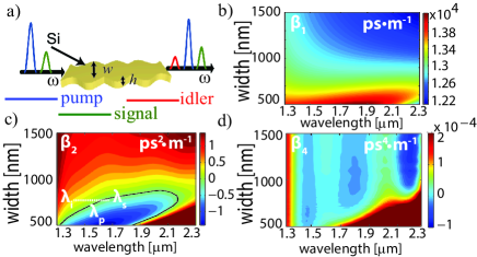
The optical waveguide considered here consists of a Si core with constant height, , and periodically modulated width, , buried in . We assume a sinusoidal dependence, , where , , and are the average width, amplitude of the width modulation, and its period, respectively, but more intricate profiles can be readily investigated by our method. As illustrated in Fig. 1(a), we consider the case of degenerate FWM, in which two photons at the pump frequency, , interact with the nonlinear medium and generate a pair of photons at signal () and idler () frequencies. This FWM process is most effective when
| (2) |
where is the Bragg wave vector, is the pump peak power, and are the mode propagation constants evaluated at the frequencies of the co-propagating pulses. Note that in Eq. (2) all width-dependent quantities are evaluated at .
If , Eq. (2) can be cast to a form that makes it more suitable to find the wavelengths of the quasi-phase-matched pulses by expanding in Taylor series the functions , around . Keeping the terms up to the fourth-order, Eq. (2) becomes:
| (3) |
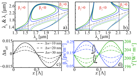
The dispersive properties of the Si-PNW, summarized in Fig. 1, define the spectral domain, in which efficient FWM can be achieved. The width dependence of the dispersion coefficients and other relevant waveguide parameters, i.e. , , and , was obtained by using a method described in detail in [17, 24]. Importantly, with a proper choice of the operating wavelength or waveguide width, the photonic wire can have both normal and anomalous GVD. The wavelengths, for which the FWM is quasi-phase-matched and determined from Eqs. (2) and (3), are plotted in Figs. 2(a) and 2(b), respectively. These results show that, as expected, for relatively small , Eqs. (2) and (3) lead to similar predictions, whereas they disagree for large . Interestingly enough, Fig. 2(a) shows that for certain ’s FWM can be achieved at more than one pair of wavelengths, , meaning that optical bistability could readily be observed in this system. The corresponding -dependence over one period of the variation of the effective modal refractive index, , , and , is presented in Figs. 2(c) and 2(d).
The wavelength conversion efficiency and parametric amplification gain are determined from the pulse spectrum. Thus, we launch into the waveguide pulses whose temporal profile, , is the superposition of a pump pulse and a weak signal, whose frequency is shifted by . The ratio is set to and in the cases of wavelength conversion and parametric amplification, respectively, so that in the latter case the signal is too weak to affect the pump. We also assume that the signal and pump have the same temporal width, , and, unless otherwise stated, the same group-velocity, .
A generic example of pulse evolution in a uniform and Bragg Si-PNW, where the latter is designed such that condition (2) holds, is presented in Fig. 3. We considered a pulse with , , , , and , so that one expects an idler pulse to form at . The waveguide parameters are , , , , , and . The evolution of the temporal pulse profile, shown in Figs. 3(a) and 3(b), suggests that the pulse propagates with a group-velocity, , slightly larger than . Indeed, the pulse propagates in the normal dispersion regime and its average frequency is smaller than , which means that . In the case of the Bragg waveguide, additional temporal oscillations of the pulse are observed. This effect is traced to the periodic variation , which is due to the implicit dependence of on a periodically varying width .
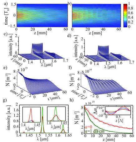
Due to its specific nature, it is more suitable to study the FWM in the frequency domain. In particular, the differences between the evolution of the pulse spectra in uniform and Bragg waveguides, illustrated by Figs. 3(c) and 3(d), respectively, underline the main physics of pulsed FWM in Si-PNWs. Specifically, it can be seen that, in the Bragg waveguide, the idler energy builds up at a much higher rate as compared to the case of the uniform Si-PNW, an indication of a much more efficient FWM interaction [see also Fig. 3(g)]. In both cases, however, we observe a gradual decrease of the the pulse peak power, induced by the linear and nonlinear losses associated to the generated FCs. Note that the dispersion length so that the dispersion-induced pulse broadening is negligible.
For the Bragg waveguide one can also observe a series of oscillations of the FC density with respect to , which are due to the periodic variation with of . Specifically, the oscillatory -variation of results in a quasi-periodic variation of the effective modal index, , which adds to the periodic variation of due to the waveguide-width modulation. Note, however, that for the power values used in this analysis the former effect is an order of magnitude weaker than the latter one [compare Fig. 2(c) with the inset in Fig. 3(h)].
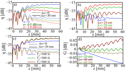
A comparative study of the conversion efficiency (CE), , and FWM gain, , in a Bragg vs. a uniform Si-PNWs is summarized in Fig. 4. The energies of the idler, , and signal, , were calculated by integrating the power spectrum over a frequency domain containing the corresponding pulse. These results clearly show that the Bragg grating induces a dramatic increase of the CE. Although the CE decreases with the waveguide loss, the CE enhancement between the uniform and Bragg waveguides only slightly varies with . Importantly, the power decay leads to the detuning of the FWM and, after a certain distance, to the degradation of its efficiency. As expected, the CE enhancement increases with , reaching for . The CE also depends on , as per Fig. 4(c). Indeed, one expects that the CE increases with since the Bragg waveguide is designed to phase-match the carrier frequencies of the pulses, so that spectrally narrower pulses are better phase-matched.
The dependence of the FWM gain on the amplitude of the width modulation is shown in Fig. 4(d). To avoid large losses due to two-photon absorption, the device is operated at mid-IR frequencies. Thus, the pulse has , , , , and , meaning that the idler is formed at . The waveguide parameters were , , , , and . The increased FWM efficiency in Bragg Si-PNWs is clearly demonstrated by these numerical experiments namely, a transition from negative to positive net gain is observed when increases from zero to . When further increases beyond a certain value, , the variation over one period of becomes large enough to greatly degrade the phase matching of the interacting pulses, resulting in a steep decrease of the FWM gain.
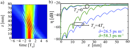
In our analysis so far we have designed the waveguide so that the pump and signal have the same group-velocity, meaning that optimum FWM is then achieved. In Fig. 5, which also considers mid-IR pulses, we present the CE determined in two cases when this condition does not hold, i.e. when the walk-off , and for two different values of the pump-signal time delay, . The main conclusion that can be drawn from these results is that when , FWM occurs only over a certain distance, which is related to the time necessary for the pump and signal pulses to pass through each other. In Fig. 5(a) this propagation section corresponds to the region where one can observe a series of intensity fringes, which are due to the frequency beating between the two pulses. Also, the CE increases rapidly as decreases because for large the pump decays more before it begins to interact with the signal, i.e. the FWM becomes more detuned. This suggests that the CE should increase with as well, in agreement with the results plotted in Fig. 5(b) for .
In conclusion, we showed that efficient pulsed FWM can be achieved in long-period Bragg silicon waveguides, which can be used for pulse amplification and to enhance the wavelength-conversion efficiency, as compared to uniform waveguides. These new ideas can be applied to a multitude of photonic devices, including photonic crystal fibers and sub-micrometer optical waveguides whose modal frequency dispersion is primarily determined by the waveguide dispersion. Equally important, by using more complex grating profiles, e.g. multi-period [17] or chirped gratings [26, 27], one can design photonic devices with enhanced functionality, including ultra-broadband sources of entangled photons and highly efficient autoresonant optical parametric amplifiers.
The work of S. L. was supported through a UCL Impact Award. R. R. G. acknowledges support from the Columbia Optics and Quantum Electronics IGERT.
References
- [1] R. H. Stolen, J. E. Bjorkholm, and A. Ashkin, Appl. Phys. Lett. 24, 308 (1974).
- [2] K. O. Hill, D. C. Johnson, B. S. Kawasaki, and R. I. MacDonald, J. Appl. Phys. 49, 5098 (1978).
- [3] R. Claps, V. Raghunathan, D. Dimitropoulos, and B. Jalali, Opt. Express 11, 2862 (2003).
- [4] D. Dimitropoulos, V. Raghunathan, R. Claps, and B. Jalali, Opt. Express 12, 149 (2004).
- [5] H. Fukuda, K. Yamada, T. Shoji, M. Takahashi, T. Tsuchizawa, T. Watanabe, J. Takahashi, and S. Itabashi, Opt. Express 13, 4629 (2005).
- [6] R. Espinola, J. Dadap, R. M. Osgood, Jr., S. McNab, and Y. Vlasov, Opt. Express 13, 4341 (2005).
- [7] M. A. Foster, A. C. Turner, J. E. Sharping, B. S. Schmidt, M. Lipson, and A. L. Gaeta, Nature 441, 960 (2006).
- [8] Q. Lin, J. Zhang, P. M. Fauchet, and G. P. Agrawal, Opt. Express 14, 4786 (2006).
- [9] N. C. Panoiu, X. Chen, and R. M. Osgood, Opt. Lett. 31, 3609 (2006).
- [10] K. Yamada, H. Fukuda, T. Tsuchizawa, T. Watanabe, T. Shoji, and S. Itabashi, IEEE Photon. Technol. Lett. 18, 1046 (2006).
- [11] Y.-H. Kuo, H. Rong, V. Sih, S. Xu, M. Paniccia, and O. Cohen, Opt. Express 14, 11721 (2006).
- [12] M. A. Foster, A. C. Turner, R. Salem, M. Lipson, and A. L. Gaeta, Opt. Express 15, 12949 (2007).
- [13] X. Liu, R. M. Osgood, Y. A. Vlasov, and W. M. J. Green, Nat. Photon. 4, 557 (2010).
- [14] S. Zlatanovic, J. S. Park, S. Moro, J. M. C. Boggio, I. B. Divliansky, N. Alic, S. Mookherjea, and S. Radic, Nat. Photon. 4, 561 (2010).
- [15] B. Kuyken, X. Liu, R. M. Osgood, R. Baets, G. Roelkens, and W. Green, Opt. Exp. 19, 20172 (2011).
- [16] X. Liu, B. Kuyken, G. Roelkens, R. Baets, R. M. Osgood, and W. M. J. Green, Nat. Photon. 6, 667 (2012).
- [17] J. B. Driscoll, N. Ophir, R. R. Grote, J. I. Dadap, N. C. Panoiu, K. Bergman, and R. M. Osgood, Opt. Express 20, 9227 (2012).
- [18] Q. Lin, O. J. Painter, and G. P. Agrawal, Opt. Express 15, 16604 (2007).
- [19] R. M. Osgood, N. C. Panoiu, J. I. Dadap, X. Liu, X. Chen, I-W. Hsieh, E. Dulkeith, W. M. J. Green, and Y. A. Vlassov, Adv. Opt. Photon. 1, 162 (2009).
- [20] Q. Lin, and G. P. Agrawal, Opt. Lett. 31, 3140 (2006).
- [21] R. Salem, M. A. Foster, A. C. Turner, D. F. Geraghty, M. Lipson, and A. L. Gaeta, Nat. Photon. 2, 35 (2008).
- [22] X. Chen, N. C. Panoiu, and R. M. Osgood, IEEE J. Quantum Electron. 42, 160 (2006).
- [23] N. C. Panoiu, X. Liu, and R. M. Osgood, Opt. Lett. 34, 947 (2009).
- [24] S. Lavdas, J. B. Driscoll, H. Jiang, R. R. Grote, R. M. Osgood, and N. C. Panoiu, Opt. Lett. 38, 3953 (2013).
- [25] R. A. Soref and B. R. Bennett, IEEE J. Quantum Electron. 23, 123 (1987).
- [26] M. B. Nasr, S. Carrasco, B. E. A. Saleh, A. V. Sergienko, M. C. Teich, J. P. Torres, L. Torner, D. S. Hum, and M. M. Fejer, Phys. Rev. Lett. 100, 183601 (2008).
- [27] O. Yaakobi and L. Friedland, Phys. Rev. A 82, 023820 (2010).