Performance of the ALICE muon trigger RPCs during LHC Run I
Abstract
ALICE (A Large Ion Collider Experiment) studies the transition of nuclear matter to a deconfined phase known as Quark Gluon Plasma, in ultra-relativistic heavy-ion collisions at the LHC. ALICE is equipped with a muon spectrometer for the detection of quarkonia and heavy flavour particles. The trigger system of the spectrometer consists of 72 RPCs arranged in four detection planes, with a total area of 140 m2. In the first three years of LHC operation, the muon trigger system was fully operational in data-taking in pp, Pb-Pb and p-Pb collisions. The RPC performance and stability throughout the whole data-taking period is presented and discussed, for the parameters such as the efficiency, the dark counting rate, the dark current and the cluster size.
keywords:
ALICE; muon trigger; RPC; detector performance1 Introduction
ALICE (A Large Ion Collider Experiment[1]) collaboration at the LHC studies nuclear matter at very high energy densities, realized in ultra-relativistic heavy-ion collisions. In these conditions, nuclear matter undergoes a phase transition to a deconfined state, known as Quark-Gluon Plasma (QGP[2]). The ALICE physics program also includes measurements in proton-proton and proton-nucleus collisions, both of which should serve as reference for the results in nucleus-nucleus collisions, as well as its own interest.
From 2009 to 2013 ALICE took data in pp, Pb-p (Pb beam directed towards the muon spectrometer), p-Pb (proton beam directed towards the muon spectrometer) and Pb-Pb collisions under different beam energy and luminosity conditions, summarised in table 1.
Quarkonium states and heavy-flavour particles are important probes of QGP, their yield being sensitive to the deconfined medium properties; the ALICE muon spectrometer[3] is used to detect them via their muonic and semi-muonic decays in the pseudo-rapidity range -4.0-2.5. The spectrometer is composed of a set of absorbers, a muon tracking system (5 planes of Cathode Pad Chambers), a dipole magnet and a muon trigger system. A detailed description of the detectors and infrastructures is given in[1]. The trigger system consists of two stations of two RPC planes each, with 18 RPCs per plane, for a total of 72 chambers. The two stations are set perpendicularly to the beam pipe, at 16 m and 17 m, respectively, from the interaction point. The total active area is about 140 m2 and the achieved spatial resolution is better than 1 cm[4]. The trigger logic exploits the RPC spatial information; the transverse momentum () selection is applied by evaluating the deviation of the muon trajectory with respect to the straight tracks, corresponding to infinite-momentum case, originating from the interaction point.
The system is able to deliver single and di-muon (unlike- and like-sign) triggers. Two thresholds can be handled simultaneously for each of these signals, so that six different triggers in total are evaluated and delivered to the ALICE trigger processor with a latency time of about 800 ns.
| Year | Colliding system | (TeV) | Maximum luminosity (cm-2 s-1) |
|---|---|---|---|
| 2010 | pp | 7 | |
| Pb–Pb | 2.76 | ||
| 2011 | pp | 7 | 21030 |
| Pb–Pb | 2.76 | 51026 | |
| pp | 2.76 | 51029 | |
| 2012 | pp | 8 | |
| 2013 | p–Pb - Pb–p | 5.02 | |
| pp | 2.76 |
The ALICE muon trigger detectors are 2 mm single-gap RPCs, with low resistivity bakelite electrodes (). The gas mixture consists of , , , for a highly saturated avalanche operating mode[5]. In this mode, the front-end electronics, called ADULT, discriminates the signals above a very low threshold of 7 mV with no pre-amplification stage[8]. In order to prevent mechanical and chemical alterations to the bakelite electrodes, the mixture is kept at a relative humidity of 37 [6][7].
The detectors are read out on both sides with orthogonal copper strips, with pitch of 1 cm, 2 cm and 4 cm and length ranging from 17 cm to 72 cm, in the X (bending plane) and Y (non-bending plane) directions. The operating high voltage ranges from 10 to 10.4 kV. Temperature and pressure variations are corrected using the information given by the online Detector Control System (DCS).
In Sec.2, the RPC performance in terms of dark rate, dark current, efficiency and cluster size are presented.
2 RPC performance
During LHC Run I, from 2009 to 2013, the RPC integrated charge was on average 4 . The charge for the most exposed detector was 7 . The largest contribution from the integrated charge comes from high-rate pp running in 2012. During the RD phase, RPCs have been successfully tested with the same gas mixture up to an exposure of 50 [5][9].
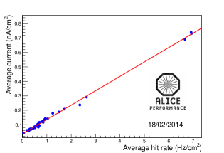
During Run I, the counting rate on the whole active surface reached values up to 7.5 for pp, 10 for Pb-p and 2 for Pb-Pb.
In figure 1 the average RPC current is shown as a function of the average hit rate: the expected linear correlation is verified, and the fitted slope gives a value of about 100 pC, which corresponds to the average charge associated to a single hit[10].
2.1 Dark rate
The dark rate is the detector counting rate with no colliding beams. It is measured in small dedicated runs just after the beam dump. The dark rate has been monitored throughout the whole running period, and the result is shown in figure 2 (left). A detailed analysis reveals a direct connection between the dark rate value and the features of the previous fill: right after high luminosity fills, the dark rate is higher than after low luminosity ones. Such an effect is most likely due to activation of the surrounding materials. Therefore, only the values measured after low luminosity fills are included in figure 2 (left).
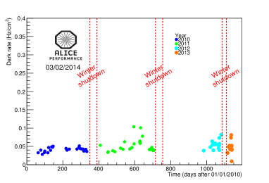
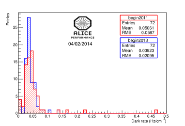
The dark rate is stable through the whole running period and its average value is always below 0.1 , in line with specifications. The observed stability with time is confirmed by the comparison of the RPC dark rate distribution in 2011 and 2013 (figure 2 right).
2.2 Dark current
The dark current has been constantly monitored during the beam-off periods: the evolution of its average value as a function of time is shown in figure 3 (left).
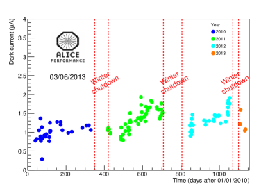
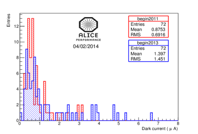
A slight overall increase of the dark current value is observed during each data-taking year, with a strong decrease after the winter shutdown, during which the detectors were left off with gas flowing. Nevertheless, an overall slight increase of the dark current from year to year is observed. The comparison between the RPC dark current distribution in 2011 and 2013 (figure 3 (right)) shows that this is due to a number of isolated detectors exhibiting a relatively large increase of the dark current.
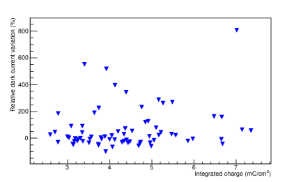
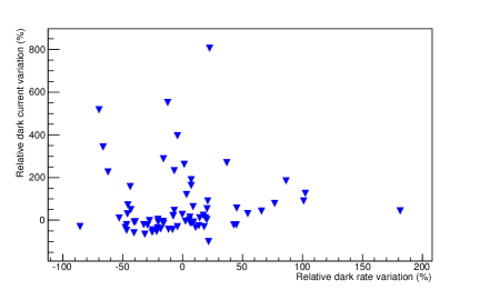
Figure 4 (left) shows the correlation between the RPC relative dark current increase from 2010 to 2013 and the RPC integrated charge. No evident correlation is observed, indicating that the effect is not related to the irradiation due to beam-beam and beam-gas collisions. Figure 4 (right) shows the correlation between the dark current increase and the dark rate increase: no evident correlation is observed, indicating that the extra-current is not related to a degradation of the electrode surface.
2.3 Efficiency
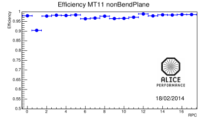
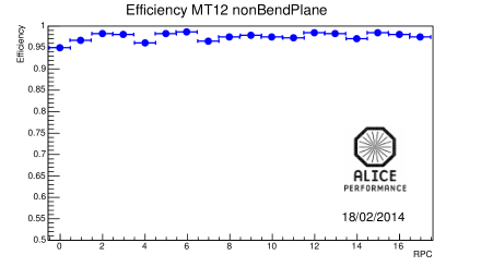
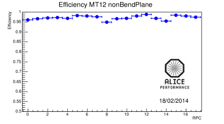
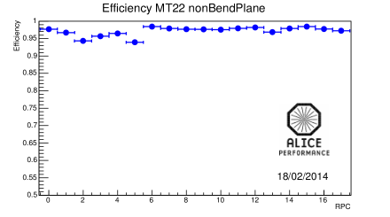
The RPC efficiency can be measured by exploiting the redundancy of the trigger algorithm, which requires hits in at least three out of four detection planes to give a positive response. Thus, the efficiency of a single detection element can be evaluated by using the remaining three planes as an external trigger and tracking system[11]. In addition to this, being the RPCs equipped with strips on both sides (bending and non-bending planes), the algorithm allows to separately measure the efficiency of the two planes.
The efficiency is measured on a weekly basis; in figure 5 its average value is shown as a function of time for the 4 detection planes.
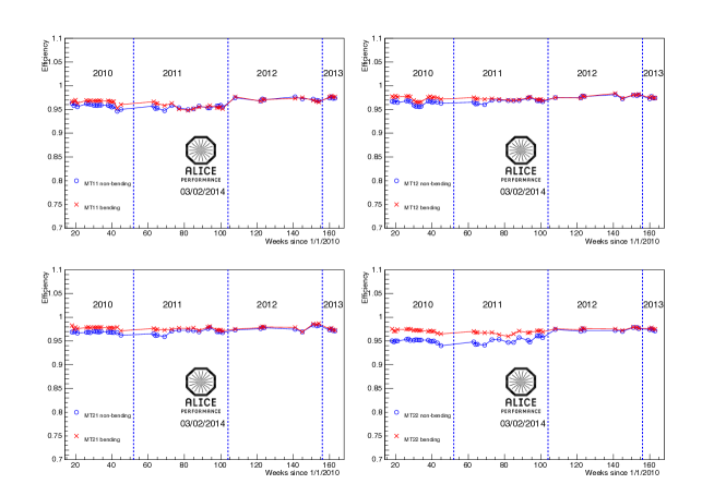
The efficiency is stable throughout the whole data-taking period, for the whole RPC system.
The individual RPC efficiency has also been studied: all the detectors, with a very few exceptions, have an efficiency larger than 95 , as can be seen in figure 6.
2.4 Cluster size
The average cluster size has been measured for all colliding systems during the three years of LHC Run I. In figure 7 the average cluster size is shown for all colliding systems (left) and as a function of time during the 2012 pp data-taking (right). The cluster size values are very similar for the different colliding systems, for strips of all pitches. During the RD phase, the average cluster size was estimated as 1.3 for 2 cm strips with a 10 mV threshold[5]. Despite the different threshold (7 mV at run time), the results obtained in the runs are very close to the RD ones.
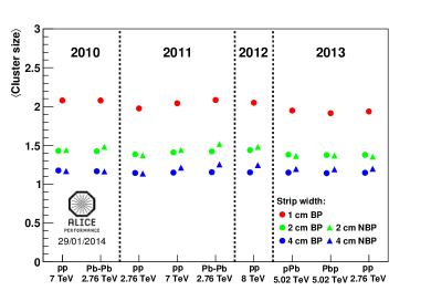
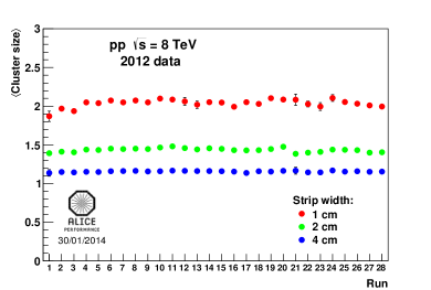
A satisfactory stability in time is also observed (figure 7 right).
2.5 Trigger efficiency
Figure 8 shows the muon trigger efficiency for detection: the ideal case (RPC 100 efficiency) and the real one (with the efficiency extracted by Pb-Pb data from 2011) are compared as a function of the transverse momentum. The ratio between the two is also shown. This is an example of how the detector performance translates into physics performance.
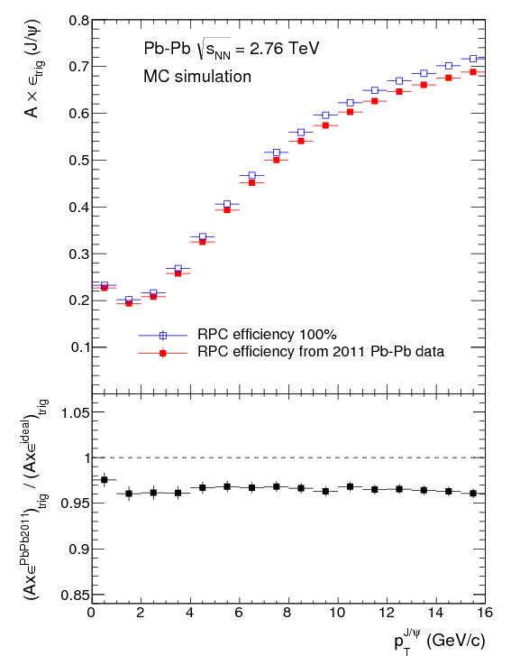
The comparison between the real and the ideal case is satisfactory, the two being always within 5. The effect of the trigger chamber inefficiencies is smaller than 5, with weak (if any) dependence.
3 Conclusions
The ALICE muon trigger system has been fully operational during LHC Run I. The observed RPC performance is in agreement with the design value. The average RPC efficiency is typically larger than 95 and stable in time; the dark rate is stable and always below 0.1 . The dark current shows a slight overall increase during data taking periods followed by a decrease after long winter stops. A few RPCs show a systematic increase of the dark current, not correlated with the integrated charge and not justified by an increase of the dark rate. The average cluster size is about 1.4 for 2 cm strips, in line with specifications.
The ALICE muon spectrometer is playing a crucial role in the ALICE physics program and it will continue to do so also during the LHC Run II, without hardware modifications. An upgrade for Run III has been planned and is now being carried out[13]. The detectors will be operated in genuine avalanche mode in order to cope with the harsher running conditions expected[14].
References
- [1] ALICE collaboration, K. Aamodt et al., The ALICE experiment at the CERN LHC, \jinst32008S08002.
- [2] F. Kartsch, Lattice simulations of the thermodynamics of strongly interacting elementary particles and the exploration of new phases of matter in relativistic heavy-ion collisions, \hrefhttp://iopscience.iop.org/1742-6596/46/1/017/ J. Phys. Conf. Ser. 46 (2006) 122 [\heplat0608003] and references therein.
- [3] ALICE Collaboration, The forward muon spectrometer of ALICE: addendum to the technical proposal for a Large Ion Collider experiment at the CERN LHC, \hrefhttp://cds.cern.ch/record/314011?ln=it CERN-LHCC-96-032 (1996).
- [4] ALICE collaboration, R. Arnaldi et al., Spatial resolution of RPC in streamer mode, \hrefhttp://dx.doi.org/10.1016/S0168-9002(02)00917-8 Nucl. Instr. Meth. A 490 (2002) 51.
- [5] R. Arnaldi et al., Beam and ageing tests with a highly-saturated avalanche gas mixture for the ALICE p-p data taking, \hrefhttp://www.sciencedirect.com/science/article/pii/S0920563206004427 Nucl. Phys. Proc. Suppl. B 158 (2006) 149.
- [6] R. Arnaldi R. et al., Ageing tests and chemical analysis of Resistive Plate Chambers for the trigger of the ALICE dimuon arm, \hrefhttp://www.sciencedirect.com/science/article/pii/S0168900204014159 Nucl. Instr. Meth. A 533 (2004) 112.
- [7] ALICE Collaboration, M. Gagliardi et al., Commissioning and first performance of the resistive plate chambers for the ALICE muon arm, \hrefhttp://www.sciencedirect.com/science/article/pii/S0168900210018097 Nucl. Instr. Meth. A 661 (2012) S45.
- [8] ALICE Collaboration, R. Arnaldi et al., Front-end electronics for the RPCs of the ALICE dimuon trigger, \hrefhttp://ieeexplore.ieee.org/xpl/articleDetails.jsp?arnumber=1495825 IEEE Trans. Nucl. Sci. 52 (2005) 1176.
- [9] F. Poggio, Beam and ageing tests of Resistive Plate Chambers for the ALICE muon spectrometer, Ph.D thesis, \hrefhttp://cds.cern.ch/record/1481321 CERN-THESIS-2006-105 , Università degli studi di Torino, Torino Italy (2006).
- [10] F. Bossu, M. Gagliardi and M. Marchisone, Performance of the RPC-based ALICE muon trigger system at the LHC, \jinst72012T12002.
- [11] D. Stocco, Development of the ALICE muon spectrometer: preparation for data taking and heavy flavor measurement, Ph.D thesis, \hrefhttp://cds.cern.ch/record/1322408 CERN-THESIS-2008-144 , Università degli studi di Torino, Torino Italy (2008).
- [12] ALICE Collaboration, B. Abelev et al., Performance of the ALICE Experiment at the CERN LHC, \hrefhttp://arxiv.org/abs/1402.4476 arXiv:1402.4476 [nucl-ex].
- [13] B. Joly, in these proceedings.
- [14] L. Musa and K. Safarik, Letter of Intent for the Upgrade of the ALICE Experiment, \hrefhttp://cds.cern.ch/record/1475243?ln=it CERN-LHCC-2012-012. LHCC-I-022.