Boosting the performance of Brillouin amplification at sub-quarter-critical densities via reduction of parasitic Raman scattering
Abstract
Raman and Brillouin amplification of laser pulses in plasma have been shown to produce picosecond pulses of petawatt power. In previous tudies, filamentation of the probe pulse has been identified as the biggest threat to the amplification process, especially for Brillouin amplification, which employs the highest plasma densities. Therefore it has been proposed to perform Brillouin scattering at densities below to reduce the influence of filamentation. However, parastic Raman scattering can become a problem at such densities, contrary to densities above , where it is suppressed. In this paper, we investigate the influence of parasitic Raman scattering on Brillouin amplification at densities below . We expose the specific problems posed by both Raman backward and forward scattering, and how both types of scattering can be mitigated, leading to an increased performance of the Brillouin amplification process.
pacs:
52.38.-r, 42.65.Re, 52.38.Bv, 52.38.HbI Introduction
Amplification of laser beams via parametric instabilities in plasma (Raman and Brillouin scattering) has been proposed a number of times maier66 ; milroy77 ; milroy79 ; capjack82 ; andreev89 , but came into its own only relatively recently shvets99 ; kirkwood99 ; ping04 ; weber1 ; ren07 ; ping09 ; lancia ; trines10 ; kirkwood11 ; trines11 ; toroker12 . Brillouin scattering has also been used to transfer energy via the Cross-Beam Energy Transfer scheme at the National Ignition Facility kruer96 ; williams04 ; michel09 ; glenzer10 ; michel10 ; hinkel11 ; moody12 . Both Raman and Brillouin scattering have been studied extensively in the context of Inertial Confinement Fusion tanaka82 ; walsh84 ; vill87 ; mori94 ; langdon02 ; lindl04 ; hinkel05 ; froula07 ; michel11 ; glenzer11 ; Raman scattering also in the context of wakefield acceleration forslund85 ; decker94 ; rousseaux95 ; karl95 ; tzeng96 ; decker96 ; moore97 ; tzeng98 ; gordon98 ; matsuoka10 . Raman and Brillouin scattering are processes where two electromagnetic waves at slightly different frequencies propagating in plasma exchange energy via a plasma wave. For Raman scattering, this is a fast electron plasma wave, while for Brillouin scattering it is a slower ion-acoustic wave forslund . When it comes to laser beam amplification, Raman and Brillouin scattering have different properties and serve different purposes. Raman amplification yields the shortest output pulses and the highest amplification ratios, but it is sensitive to fluctuations in the experimental parameters and requires high accuracy in the matching of laser and plasma frequencies. Brillouin amplification yields lower peak intensities or amplification ratios, but is far more robust to parameter fluctuations or frequency mismatch, more efficient (as less laser energy stays behind in the plasma wave) and more suitable for the production of pulses with a high total power or energy.
Previous investigations into Raman and Brillouin scattering identified filamentation as the most important limiting factor for succesful amplification trines10 ; alves14 . This is especially true for Brillouin amplification, since it employs higher plasma densities than Raman amplification. Thus, it has been proposed to reduce the plasma density for Brillouin amplification from weber1 to weber13 ; riconda13 , where denotes the background plasma electron density and denotes the critical density for the wave length of the pump laser. However, while stimulated Raman scattering (SRS) is suppressed for , it is possible at any density below forslund , and can be expected to interfere with the Brillouin amplification process. Examples of strong longitudinal pulse envelope modulations and intense prepulses preceding the amplified probe pulse, all induced by Raman forward scattering, have been observed before riconda13 ; alves14 . Therefore, we need to investigate the influence of stimulated Raman scattering (both backward and forward) on Brillouin amplification at sub-quarter-critical densities. This will be done as follows. First, we will give a summary of the self-similar theory of Brillouin amplification in the strong-coupling regime weber1 ; alves14 . Next, we will thoroughly analyse the results of a particle-in-cell (PIC) simulation of a scenario where strong SRS is likely to occur: laser beam intensities of W cm-2 for a waven length of 1 m and . Finally, we will carry out a thorough parameter scan to identify the parameters for the pump laser and the plasma column where the best results (highest amplification factor, lowest relative level of parasitic SRS) can be obtained. We will also investigate and discuss the impact of using non-constant plasma density profiles, as proposed by Riconda et al. riconda13 .
II Self-similar theory of Brillouin amplification
We start from a homogeneous plasma with electron number density , plasma frequency , ion plasma frequency , electron/ion temperatures and , electron thermal speed , Debye length , and a pump laser pulse with wave length , intensity , frequency , dimensionless amplitude , where () denotes linear (circular) polarisation, and wave group speed . Let the durations of pump and probe pulse be given by and , and define , the Brillouin scattering growth rate in the strong-coupling regime forslund . Expansion of the self-similar coordinate of Ref. weber1 , and application of the energy balance yields:
| (1) | ||||
| (2) |
where is a numerical constant and denotes the pump depletion efficiency. The physical interpretation of Eq. (1) is that the duration of the probe pulse is similar to the time it takes the probe to deplete the counterpropagating pump: for increasing pump intensity or probe amplification (i.e. longer ), pump depletion is more rapid and decreases. This allows one to tune the final probe duration via the properties of the pump beam, similar to Raman amplification trines11 . Eq. (2) implies that the initial probe pulse duration is not a free parameter: this equation dictates the optimal initial probe pulse duration for a given initial probe pulse amplitude .
From previous numerical work on Raman kim03 ; trines11 and Brillouin amplification lehmann13 , it follows that if the probe pulse is too short for its amplitude initially, it will reshape itself first to fulfil Eq. (2), and only then start to amplify. Ensuring that the probe pulse fulfils Eq. (2) from the start will speed up the amplification process and increase the efficiency. For that reason, we will vary the plasma density, pump intensity and the interaction length in our simulations, but the initial probe pulse intensity will be chosen equal to the pump intensity, and the probe duration will be treated as a dependent parameter and calculated using Eq. (2).
III Parasitic instabilities at sub-quarter-critical densities
III.1 Theory
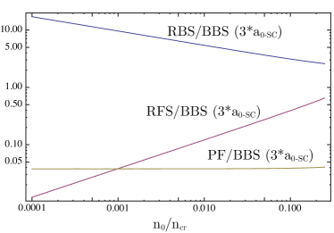
In order to assess the relative importance of various competing processes, we have calculated the growth rates for Raman backward scattering (), Raman forward scattering (), ponderomotive filamentation ( in the limit , kaw73 ), relativistic filamentation (, max74 ) and strong-coupling Brillouin backward scattering (, see above), for . The pump field amplitude was chosen to be three times the threshold value for strong-coupling Brillouin scattering forslund , i.e. . We made this particular choice because we found earlier that the pump pulse amplitude should be as low as possible, but still above the strong-coupling threshold, for optimal results alves14 . With these adjustments to the pump intensity, the density dependence of the various growth rates is as follows:
| (3) | ||||
| (4) | ||||
| (5) | ||||
| (6) | ||||
| (7) |
These growth rates are plotted in Figure 1; all growth rates are shown relative to the Brillouin scattering growth rate. For our particular configuration, we find that the growth rate for the ponderomotive filamentation does not change with density, while the RBS growth rate increases and the RFS growth rate decreases with decreasing plasma density. As will be confirmed in our simulation results below, a density of is really too high, driving too much RFS, while much better results can be obtained for densities around . At even lower densities, e.g. , one has to worry that the growth rate for Brillouin scattering becomes too low for this process to be useful, while the plasma frequency becomes low enough that the (anti-)Stokes side bands of Raman scattering, located at , may fall within the bandwidth of the probe pulse and may be directly driven by it. This fixes the useful density interval to roughly .
It should be noted that the adjusted growth rate of Raman backscatter increases for decreasing plasma density because the pump laser intensity is increased in order to remain above the threshold for strong-coupling Brillouin scattering. However, we do not observe a corresponding increase in the overall level of RBS in our numerical simulations. It is conjectured that RBS saturates at lower densities due to wave breaking of the RBS Langmuir wave, since the amplitude threshold for wave breaking scales as .
III.2 Numerical simulations
We have carried out a sequence of one-dimensional particle-in-cell (PIC) simulations using the code OSIRIS osiris1 ; osiris2 ; osiris3 . Parameters varied in these simulations are the plasma density ( or 0.01), the pump intensity (, or W cm-2) and the interaction length. The initial seed pulse intensity was chosen to be the same as the pump intensity, and the seed duration was be half the value predicted by (2). The plasma column was given a constant density, and had a fixed length. The simulations were conducted in a static window, since we needed to study the pump pulse reflection due to Raman backward scattering. The computational demands of the simulations forced us to conduct them in one dimension; even so, useful trends could be unearthed. Although filamentation cannot be modelled in 1-D simulations, we expect that it will decrease in importance for lower densities, as its growth rate scales quite quickly with density: kaw73 ; max74 . The plasma profile is basically a plateau with length and very steep ramps; the pump laser pulse has an FWHM duration of . We perform each of these simulations for 3 different plasma plateau lengths corresponding to , and RBS growth lengths for the pump pulse, where the growth length is given by . This ensures that the levels of premature pump RBS are comparable between various pulse intensities and plasma densities. We use a spatial resolution of , in order to accurately describe the thermal nature of the ion acoustic wave, and use particles per cell per species with cubic interpolation for the current deposition. Absorbing boundary conditions are imposed for the electromagnetic fields.

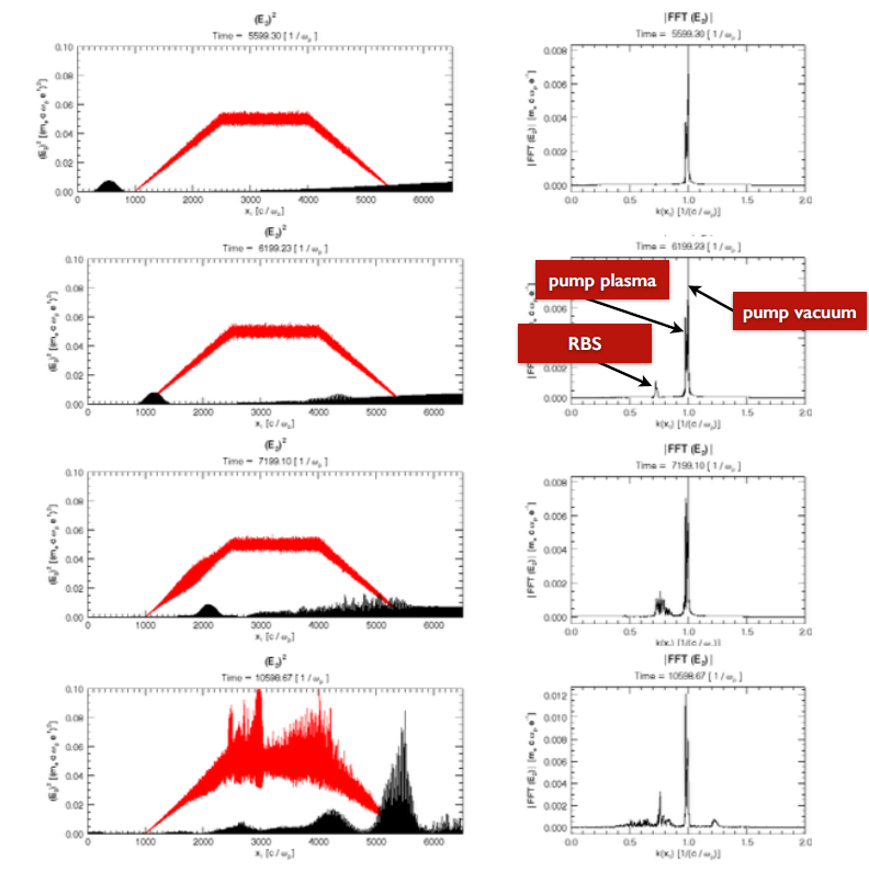
To investigate the deleterious influence of Raman back- and forward scattering (RBS and RFS), we have carried out an exploratory 1-D static-window simulation at using typical parameters: a plasma slab with electron density and length 0.8 mm and laser pulses with intensities of W/cm2 and a duration (pump) of 2.7 ps. The results of this simulation are displayed in Figure 2, left. As shown in Figure 2(a), RBS was found to generate a large prepulse to the growing probe pulse, spoiling its contrast, while RFS causes the probe pulse envelope to be strongly modulated, rendering it about as dangerous as filamentation. A Fourier analysis of the -spectrum of the pulses, shown in Fig. 2(b) and (c), reveals that the pump pulse mostly suffers from Raman backward scattering, while Raman forward scattering is dominant in the probe pulse. A close inspection of all Raman scattering occurring during Brillouin amplification found that the growth of the probe pulse saturates due to high levels of Raman forward scattering, rather than Raman backscattering. If the level of RFS in the probe pulse becomes non-linear, the coherence of the probe pulse’s carrier wave, and thus the coupling between pump and probe, is lost, and probe amplification stops; this can be seen in Figure 2(a1). It was also found that high levels of pump RFS are a good indicator of non-linear probe RFS. Fortunately, reduction of RFS can be achieved via a reduction in plasma density, which effects the RFS growth rate more than any other growth rate: , while . It follows that lowering the plasma density even further, e.g. to , will immediately improve the pump-to-probe amplification ratio and energy transfer.
From the results of our first simulation, it is obvious that stimulated Raman scattering needs to be controlled, if one wishes to conduct brillouin amplification at densities below . To this end, we have conducted a sequence of 1-D particle-in-cell simulations, where we varied the pump laser intensity, the plasma density, and the interaction length, as described above. A summary of all sub-quarter-critical simulations, listing the pump-to-probe amplification ratio for each, is given in Table 1. It is immediately clear that a plasma density of yields better results than ; this is found to be mainly caused by a reduction in RFS, which delays saturation of the growing probe. An intensity of W cm-2 also yields better results than an intensity of W cm-2: the final intensity may have a lower absolute value, but the relative compression and amplification ratios are much higher. Results deteriorate again for W cm-2, but this is possibly because these simulations could have been continued beyond 100 RBS growth lengths. As it happens, RFS is the main limiting instability rather than RBS, and the RFS growth length increases faster than the RBS growth length when the density decreases, thus even an interaction distance of 100 RBS growth lengths is “too short” for RFS to reach problematic levels.
| 10 | 30 | 100 | 10 | 30 | 100 | |
|---|---|---|---|---|---|---|
| 1.33 | 2.33 | 2.47 | 1.13w | 1.40w | 3.16w | |
| 1.35 | 2.06 | 4.76 | 1.09 | 1.46 | 6.3 | |
| 1.11 | 2.80 | 2.35 | 1.02 | 1.14 | 3.02 | |
The results of Table 1 can be summarised as follows. (i) For an interaction length of , parasitic RBS remains at a low level, but the amplification ratio is very small; the highest ratio obtained is 1.35 for and a W cm-2 pump pulse. (ii) For an interaction length of or , the amplification ratio improves, e.g. a ratio of 6.3 was obtained for and a W cm-2 pump pulse, but the level of RBS increases proportionally, reaching up to 10% of the pump energy for a interaction length. (iii) The amplification ratio increases for decreasing intensity, but only if the pump intensity/amplitude is above the threshold for strong coupling, given by , where and . For pump intensities below this threshold, the amplification ratio decreases again. (iv) Simulations at had to be abandoned since the level of parasitic RBS became intolerable. For comparison, Riconda and Weber weber13 ; riconda13 used , a W cm-2 pump pulse and a interaction length, and obtained amplification ratios of 8–10 (for a W cm-2 initial probe intensity), but at a cost of a high level of unwanted RBS, almost equalling the level of (wanted) BBS in some cases, as well as significant modulation of the seed envelope by RFS, as is clear from the frequency spectra in Ref. riconda13 .
Raman forward scattering puts an upper limit on the compression and amplification ratios that can be reached for sub-quarter-critical densities. For example, it was shown that a probe pulse could be amplified from W cm-2 to W cm-2 and from W cm-2 to W cm-2 in two separate simulations at weber13 ; riconda13 . However, this does not imply that amplification from W cm-2 to W cm-2 is possible for the same probe pulse, because the probe RFS generated during the first stage will saturate the amplification during the second stage well before an intensity of W cm-2 is reached.
As shown above, lowering the plasma density will immediately improve the pump-to-probe amplification ratio and energy transfer, but it may also reduce the Brillouin backscattering growth rate, especially at the beginning of the interaction when the probe intensity is still low. Using a plasma density profiles with a “ramp” rather than a “plateau”, with the highest plasma density facing the probe pulse, as proposed by Weber, Riconda et al. weber13 ; riconda13 , could be a good compromise in this case. We investigated this in a simulation with a trapezoidal density profile (a plateau of 0.24 mm with ramps of 0.24 mm on either side) instead of a constant plasma density throughout. A significant reduction in premature pump RFS was found, causing an improvement in probe growth (amplification factors of up to 10 were found for “ramp” profiles), simply because the average plasma density is lower for a “ramp” profile than for a “plateau”. Brillouin growth is still kickstarted by the high plasma density at the end facing the incoming probe pulse. Results are shown in Figure 3. It should be noted that frequency matching between pump, probe and ion-acoustic frequencies is not really an issue here, even in the presence of a density ramp, since the ion-acoustic frequency is so small that the frequency difference between the pump and probe pulses is always fully covered by the bandwidth of the probe pulse. Conversely, the non-constant plasma density and electron plasma frequency may strongly impact the growth of all forms of Raman scattering, which is rather beneficial in this case.
IV Conclusions
We have studied Brillouin amplification of short laser pulses in plasma at electron densities . At such densities, filamentation of the growing probe laser pulse is reduced compared to e.g. , but stimulated Raman scattering, which is inhibited for , suddenly becomes possible and introduces extra complications. Raman backscattering of the pump pulse adds a large pre-pulse to the amplified probe, while Raman forward scattering of the probe itself causes strong envelope modulations and a reduction of pulse quality. Even worse, non-linear Raman forward scattering destroys the coherence of the probe pulse’s carrier wave, inhibiting further Brillouin amplification. Therefore, parasitic Raman scattering needs to be reduced at all cost in order to boost Brillouin amplification at sub-quarter-critical plasma densities.
Fortunately, the RFS growth rate scales much faster with the plasma density than the BBS growth rate ( versus ), so reducing the plasma density will immediately reduce RFS levels without compromising the Brillouin amplification process too much. We have performed a range of 1-D particle-in-cell simulations where we varied the pump laser intensity, the plasma density and the interaction length. The simulation results showed that lowering either the plasma density or the pump intensity led to a significant improvement in the amplification and compression ratios, as well as the quality of the amplified pulse. The best result obtained was for and a pump intensity of W cm-2, although there are strong indications that even better results can be obtained by increasing the interaction length for the simulations at W cm-2 pump intensity and . In particular, we conclude that Brillouin amplification should be conducted at densities for which RFS is either impossible () or unimportant (). For , the disadvantage of increased pump RBS and probe RFS is more serious than the advantage of reduced probe filamentation.
As a compromise between using a higher density to improve Brillouin scattering and a lower density to reduce Raman scattering, one can use a plasma density profiles with a “ramp” rather than a “plateau”, with the highest plasma density facing the probe pulse. This will stimulate Brillouin scattering during the early stages of the interaction, when the probe intensity is still low, while reducing Raman forward scattering later on, when the probe intensity is much higher. Initial simulations of this scenario showed a reduction in RFS accompanied by an improvement in probe amplification and quality, so the use of tailored plasma density profiles deserves further investigation.
This work was supported by the STFC Central Laser Facility, the STFC Centre for Fundamental physics and by EPSRC through grant EP/G04239X/1. We would like to thank R. Kirkwood for stimulating discussions and the OSIRIS consortium for the use of OSIRIS. We acknowledge PRACE for providing access to the resource SuperMUC based in Germany at the Leibniz research center. Simulations were performed on the Scarf-Lexicon Cluster (STFC RAL), the IST Cluster (IST Lisbon) and SuperMUC (Leibniz Supercomputing Centre, Garching, Germany).
References
- (1) M. Maier, W. Kaiser, and J. A. Giordmaine, Phys. Rev. Lett. 17, 1275 (1966).
- (2) R. D. Milroy, C. E. Capjack, and C. R. James, Plasma Phys. 19, 989, (1977).
- (3) R. D. Milroy, C. E. Capjack, and C. R. James, Phys. Fluids 22, 1922 (1979).
- (4) C. E. Capjack, C. R. James, and J. N. McMullin, J. Appl. Phys. 53, 4046 (1982).
- (5) A. A. Andreev and A. N. Sutyagin, Sov. J. Quantum Electron. 19, 1579 (1989).
- (6) V.M. Malkin, G. Shvets and N.J. Fisch, Phys. Rev. Lett. 82, 4448 (1999).
- (7) R. Kirkwood et al., Phys. Rev. Lett. 83, 2965 (1999).
- (8) Y. Ping et al., Phys. Rev. Lett. 92, 175007 (2004).
- (9) A.A. Andreev et al., Phys. Plasmas 13, 053110 (2006).
- (10) J. Ren et al., Nature Physics 3, 732-736 (2007).
- (11) Y. Ping et al., Phys. Plasmas 16, 123113 (2009).
- (12) L. Lancia et al., Phys. Rev. Lett. 104, 025001 (2010).
- (13) R.M.G.M. Trines et al., Nature Physics 7, 87 (2011).
- (14) R.K. Kirkwood et al., Phys. Plasmas 18, 056311 (2011).
- (15) R.M.G.M. Trines et al., Phys. Rev. Lett. 107, 105002 (2011).
- (16) Z. Toroker, V. M. Malkin and N. J. Fisch, Phys. Rev. Lett. 109, 085003 (2012).
- (17) W.L. Kruer et al., Phys. Plasmas 3, 382 (1996).
- (18) E.A. Williams et al., Phys. Plasmas 11, 231 (2004).
- (19) P. Michel et al., Phys. Plasmas 16 042702 (2009).
- (20) S.H. Glenzer et al., Science 327, 1228 (2010).
- (21) P. Michel et al., Phys. Plasmas 17 056305 (2010).
- (22) D.E. Hinkel et al., Phys. Plasmas 18 056312 (2011).
- (23) J.D. Moody et al., Nature Physics 8, 344 (2012).
- (24) K. Tanaka et al., Phys. Rev. Lett. 48, 1179 (1982).
- (25) C.J. Walsh, D.M. Villeneuve and H.A. Baldis, Phys. Rev. Lett. 53, 1445 (1984).
- (26) , D. M. Villeneuve, H. A. Baldis, and J. E. Bernard, Phys. Rev. Lett. 59, 1585 (1987).
- (27) W.B. Mori et al., Phys. Rev. Lett. 72, 1482 (1994).
- (28) A. B. Langdon and D. E. Hinkel, Phys. Rev. Lett. 89, 015003 (2002).
- (29) J.D. Lindl et al., Phys. Plasmas 11 339 (2004).
- (30) D.E. Hinkel et al., Phys. Plaasmas 12, 056305 (2005).
- (31) D.H. Froula et al., Phys. Plasmas 14, 055705 (2007).
- (32) P. Michel et al., Phys. Rev. E 83, 046409 (2011).
- (33) S.H. Glenzer et al., Phys. Rev. Lett. 106, 085004 (2011).
- (34) D.W. Forslund et al., Phys. Rev. Lett. 54, 558 (1985).
- (35) C.D. Decker, W.B. Mori and T. Katsouleas, Phys. Rev. E 50, R3338 (1994).
- (36) C. Rousseaux et al., Phys. Rev. Lett. 74, 4655 (1995).
- (37) K. Krushelnick et al., Phys. Rev. Lett. 75, 3681 (1995).
- (38) K.-C. Tzeng, W.B. Mori, and C.D. Decker, Phys. Rev. Lett. 76, 3332 (1996).
- (39) C.D. Decker et al., Phys. Plasmas 3, 1360 (1996).
- (40) C.I. Moore et al., Phys. Rev. Lett. 79, 3909 (1997).
- (41) K.-C. Tzeng and W.B. Mori, Phys. Rev. Lett. 81, 104 (1998).
- (42) D. Gordon et al., Phys. Rev. Lett. 80, 2133 (1998).
- (43) T. Matsuoka et al., Phys. Rev. Lett. 105, 034801 (2010).
- (44) D.W. Forslund, J.M. Kindel and E.L. Lindman, Phys. Fluids 18, 1002-1016 (1975).
- (45) E.P. Alves, R.M.G.M. Trines et al., submitted (2014).
- (46) J. Kim, H.J. Lee, H. Suk and I.S. Ko, Phys. Lett. A 314, 464 (2003).
- (47) G. Lehmann and K. H. Spatschek, Phys. Rev. E 87, 063107 (2013); ibid. Phys. Plasmas 20, 073112 (2013).
- (48) S. Weber et al., Phys. Rev. Lett. 111, 055004 (2013).
- (49) C. Riconda et al., Phys. Plasmas 20, 083115 (2013).
- (50) R.A. Fonseca, L.O. Silva, F.S. Tsung, et al., Lect. Not. Comp. Sci. 2331, 342-351 (2002).
- (51) R. A. Fonseca, L. O. Silva, J. Tonge et al., Phys. Plasmas 10, 1979 (2003).
- (52) R. A. Fonseca, S. F. Martins, L. O. Silva et al., Plasma Phys. Contr. Fusion, 50, 12 (2008).
- (53) P. Mardahl et al., Bull. Am. Phys. Soc. 46, DPP 2001, KP1.108 (2001); P. Mardahl, Ph.D. thesis, University of California, Berkeley (2001).
- (54) K.A. Humphrey, R.M.G.M. Trines et al., Phys. Plasmas 20, 102114 (2013).
- (55) G. M. Fraiman, N. A. Yampolsky, V. M. Malkin and N. J. Fisch, Phys. Plasmas 9, 3617 (2002).
- (56) P. Kaw, G. Schmidt, and T. Wilcox, Phys. Fluids 16, 1522 (1973).
- (57) C.E. Max, J. Arons and A.B. Langdon, Phys. Rev. Lett. 33, 209 (1974).
- (58) S. Hüller, P. Mulser and A. M. Rubenchik, Phys. Fluids B 3, 3339 (1991).