Cavity solitons in vertical-cavity surface-emitting lasers
Abstract
We investigate a control of the motion of localized structures of light by means of delay feedback in the transverse section of a broad area nonlinear optical system. The delayed feedback is found to induce a spontaneous motion of a solitary localized structure that is stationary and stable in the absence of feedback. We focus our analysis on an experimentally relevant system namely the Vertical-Cavity Surface-Emitting Laser (VCSEL). In the absence of the delay feedback we present experimental evidence of stationary localized structures in a 80 m aperture VCSEL. The spontaneous formation of localized structures takes place above the lasing threshold and under optical injection. Then, we consider the effect of the time-delayed optical feedback and investigate analytically the role of the phase of the feedback and the carrier lifetime on the self-mobility properties of the localized structures. We show that these two parameters affect strongly the space time dynamics of two-dimensional localized structures. We derive an analytical formula for the threshold associated with drift instability of localized structures and a normal form equation describing the slow time evolution of the speed of the moving structure.
I Introduction
Transverse localized structures often called cavity solitons were observed experimentally in Vertical-Cavity Surface-Emitting Laser (VCSEL) Taranenko2000 ; Barland . Due to the maturity of the semiconductor technology and the possible applications of localized structures of light in all-optical delay lines Pedaci08 and logic gates Jacobo2012 , these structures in VCSELs have been a subject of an active research in the field of nonlinear optics. Moreover, the fast response time of VCSELs makes them attractive devices for potential applications in all-optical control of light. Localized structures appear as solitary peaks or dips on homogeneous background of the field emitted by a nonlinear microresonator with a high Fresnel number. Here, we report experimental evidence of spontaneous formation of localized structures in a 80 m diameter VCSEL biased above the lasing threshold and under optical injection. Such localized structures are bistable with the injected beam power and the VCSEL current.
Various mechanisms have proven to be responsible for the generation of localized structures (LS) in VCSELs: coherent optical injection (holding beam, i.e. the part of the optical injection that is used to ensure bistability of the system) in combination with a narrow writing beam (the part of optical injection which is used to locally make the system evolve from the lower branch of the bistability curve to the higher branch and vice versa)Barland , frequency selective feedback with Tanguy08 or without Radwell a writing beam, saturable absorption Genevet , amplifiers Menesguen , optically injected lasers Larionova ; Hachair2006 , “spatial translational coupling” introduced in Haudin ; delCampo , and others (see Barbay for a review). LS can start to move spontaneously in the laser transverse section in the presence of saturable absorption Fedorov . In particular, in the case when the pump beam has a circular shape LS move along the boundary on a circular trajectory PratiEPJD . It has been shown that they can undergo a spontaneous motion under the thermal effects Spinelli ; Scroggie . Delayed feedback control is a well documented technique that has been applied to various spatially extended systems in optics, hydrodynamics, chemistry, and biology. It has been demonstrated recently that a simple feedback loop provides a robust and a controllable mechanism for the motion of localized structures (LS) and localized patterns Tlidi09 ; Panajotov10 ; Tlidi12 ; Gurevich13 ; Tlidi-sonnino ; Gurevich13a ; Pimenov . These works demonstrated that when the product of the delay time and the feedback rate exceeds some threshold value, localized structures start to move in an arbitrary direction in the transverse section of the device. In these studies, the analysis was restricted to the specific case of nascent optical bistability described by the real Swift-Hohenberg equation with a real feedback term. More recently, analytical study supported by numerical simulations revealed the role of the phase of the delayed feedback and the carrier lifetime on the motion of cavity solitons in a broad-area VCSEL structure, driven by a coherent externally injected beam. We show that for certain values of the feedback phase LS can be destabilized via a drift bifurcation leading to a spontaneous motion of a solitary two-dimensional LS Tlidi09 . We demonstrate also that the slower is the carrier decay rate in the semiconductor medium, the higher is the threshold associated with the motion of cavity solitons.
The paper is organized as follows: In Sec. 2, we discuss the experimental observation of stationary LS in medium size VCELS. In Sec. 3, we introduce model equations. In Sec. 4, we investigate the drift instability induced by delay feedback. We conclude in Sec. 5.
II Experimental observation of stationary LS in medium size VCELS
In recent years, a considerable amount of experimental work has been realized on stationary localized structures in Vertical-Cavity Surface-Emitting Lasers (VCSELs). They were observed in very broad (aperture ) Barland , broad (m) Averlant_oe14 , and medium () Hachair_pra09 size VCSELs. Here we present experimental results obtained with bottom-emitting InGaAs multiple quantum well VCSEL with and threshold current of 42.5 mA at 20∘C. The holding (injection) beam is provided by a commercial tunable semiconductor laser (Sacher Lasertechnik TEC100-0960-60 External Cavity Diode Laser), isolated from the rest of the setup by an optical isolator (OFR IO5-TiS2-HP). The long-term electrical and temperature stability of this laser are less than 20 mA RMS and 0.05 ∘C, respectively. A half-wave plate is used to adjust the linear polarization of the holding beam to be the same as the one of the VCSEL. The injection beam power is tuned using a variable optical density filter. The detuning between the master laser and the VCSEL is defined as , where is the frequency of the injection beam, and the frequency of the strongest peak in the spectrum of the stand-alone VCSEL. It is experimentally tuned by changing the wavelength of the injection beam. The beam waist is defined as the diameter of the smallest circle in the plane of propagation of the injection beam containing half of the beam power when it encounters the VCSEL. The power of the source is monitored by a Newport 818-SL photodiode connected to a Newport 2832-C powermeter. The near field is recorded by imaging it on a CCD camera.
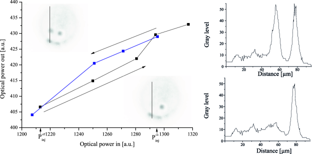
An example of stationary LSs is presented in the Fig. 1 illustrating the process of spontaneous creation and annihilation of two-dimensional localized structures. These experimental measurements have been performed when the VCSEL operated in an injection locked regime. The injection beam waist and the detuning are fixed to m and = -146 GHz. When increasing the injected beam power, a new LS appears at as shown in the insets of Fig. 1. This results in a slight jump of the total output power as shown in light-versus-current characteristics. The process of switching-off is realized when decreasing the injection power: the recently created LS persists until with , i.e. a hysteresis region exists with an additional LS either turned on or off. The two figures on the right show one dimensional scans along the vertical lines indicated in the near field images.
III Model equations
The mean field model describing the space-time evolution of the electric field envelope and the carrier density in a VCSEL subjected to optical injection is given by the following set of dimensionless partial differential equations
| (2) |
Here the parameter describes the linewidth enhancement factor, and are the cavity decay rate and the cavity detuning parameter, respectively. Below we will assume to be small enough, so that we can neglect the dependence of the parameters and on . The parameter is the amplitude of the injected field, is the bistability parameter, is the carrier decay rate, is the injection current, and is the carrier diffusion coefficient. The diffraction of light and the diffusion of the carrier density are described by the terms and , respectively, where is the Laplace operator acting in the transverse plane . Below we consider the case when the laser is subjected to coherent delayed feedback from an external mirror. To minimize the effect of diffraction on the feedback field we assume that the external cavity is self-imaging Tlidi09 . The feedback is characterized by the delay time , the feedback rate , and phase , where is the external cavity length, and is the speed of light. The link between dimensionless and physical parameters is provided in Panajotov10 . Using the expression for the feedback rate given in Tartwijk , where () is the power reflectivity of the feedback (VCSEL top) mirror and is the VCSEL cavity round trip time, we see that the necessary condition for the appearance of the soliton drift instability Tlidi09 can be rewritten in the form . In particular, for and the latter inequality becomes .
IV Drift instability threshold
When the delayed feedback is absent, , Eqs. (III) and (2) are transformed into the well-known mean field model Spinelli_pra98 , which supports stable stationary patterns and LSs Barland ; Hachair04 ; Hachair05 ; Hachair_pra09 . It was demonstrated recently that when the feedback rate exceeds a certain threshold value, which is inversely proportional to the delay time , LS starts to move in the transverse direction Tlidi09 . Example of moving two-dimensional LS are shown in Fig. 2. The single and the three moving peaks are obtained from numerical simulations of Eqs. (III) and (2). The boundary condition are periodic in both transverse dimensions.
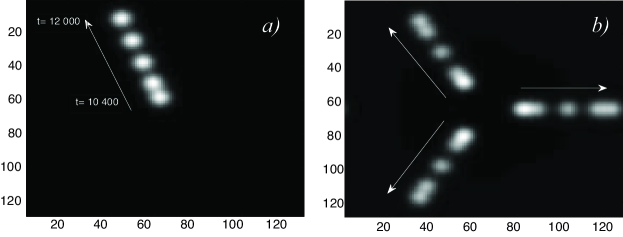
In the case when the system is transversely isotropic, the velocity of the LS motion has an arbitrary direction. The self-induced motion of the LS is associated with a pitchfork bifurcation where the stationary LS looses stability and a branch of stable LSs uniformly moving with the velocity bifurcates from the stationary LS branch. The bifurcation point can be obtained from the first order expansion of the uniformly moving LS in power series of the small velocity . Close to the pitchfork bifurcation point this expansion reads:
| (3) | |||
| (4) |
where without the loss of generality we assume that the LS moves along the -axis on the -plane. Here and describes the stationary axially symmetric LS profile, which corresponds to the time-independent solution of Eqs. (III) and (2) with . Although formally this solution depends on the feedback parameters and we neglect this dependence assuming that the feedback rate is sufficiently small, . Substituting this expansion into Eqs. (III) and (2) and collecting the first order terms in small parameter we obtain:
| (11) |
where the linear operator is given by
By applying the solvability condition to the right hand side of Eq. (3), we obtain the drift instability threshold
| (12) |
with
| (13) |
Here
| (14) |
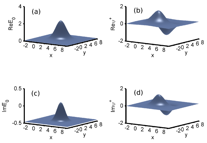
is a translational neutral mode of the operator , , while is the corresponding solution of the homogeneous adjoint problem . The scalar product is defined as . To estimate the coefficients and we have calculated the function numerically using the relaxation method in two transverse dimensions, . The results of these calculations are shown in Fig. 3 together with the axially symmetric profile of the stationary LS. It is seen from this figure that similarly to the neutral mode defined by (14) the neutral mode of the adjoint operator is an even function of the coordinate and an odd function of the coordinate , which is parallel to the LS direction of motion.
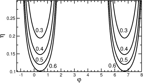
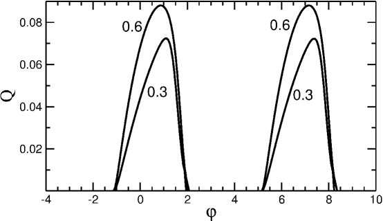
The dependence of the critical feedback rate corresponding to the drift instability threshold defined by Eq. (12) on the feedback phase and carrier relaxation rate is illustrated by Fig. 4. In this figure the curves labeled by different numbers correspond to different values of . Considering the fact that the feedback in Eq. (III) is introduced with the minus sign, we see that the drift instability takes place only for those feedback phases when the interference between the cavity field and the feedback field is destructive, i.e. when function in the denominator of the right hand side of Eq. (12) is positive. On the contrary, when this interference is constructive the feedback has a stabilizing effect on the LS. Furthermore, the slower is the carrier relaxation rate, the higher is the drift instability threshold. Since the stationary LS solution does not depend on the carrier relaxation rate , the coefficients and in the threshold condition (12) are also independent of . Therefore, (12) gives an explicit dependence of the threshold feedback rate on the carrier relaxation rate. In particular, in the limit of very fast carrier response, , and zero feedback phase, , we recover from (12) the threshold condition which was obtained earlier for the LS drift instability induced by a delayed feedback in the real Swift-Hohenberg equation Tlidi09 . Note that at , , and the critical feedback rate appears to be smaller than that obtained for the real Swift-Hohenberg equation, .
As it was demonstrated above, the bifurcation threshold responsible for self-induced drift of LS in the VCSEL transverse section is obtained by expanding the slowly moving localized solution in the small velocity , substituting this expansion into the model equations (III),(2), and equating the first order terms in . In order to describe the slow evolution of the LS velocity slightly above the bifurcation threshold one needs to perform a similar procedure with and , where , and is a small parameter characterizing the distance from the bifurcation point. Then, omitting detailed calculations, in the third order in , we obtain the normal form equation for the LS velocity:
| (15) |
where is the deviation of the feedback rate from the bifurcation point. The coefficients , , and are given by , , and , respectively. Here , , and are defined by Eq. (13) and , , . The stationary LS velocity above the drift instability threshold is obtained by calculating the nontrivial steady state of Eq. (15), , where the coefficient determines how fast the LS velocity increases with the square root of the deviation from the critical feedback rate. The dependence of this coefficient on the feedback phase is illustrated by Fig. 5.
V Conclusion
To conclude, we have studied experimentally the formation of transverse LS in a medium size bottom-emitting InGaAs multiple quantum well VCSEL operated in an injection locked regime. Creation and annihilation of a single localized structure have been demonstrated by changing the injection beam power. Theoretically we have analyzed the effect of delayed feedback from an external mirror on the stability of transverse LS in a broad area VCSEL. We have shown that depending on the phase of the feedback it can have either destabilizing or stabilizing effect in the LS. In particular, when the interference between the LS field and the feedback field is destructive, the LS can be destabilized via a pitchfork bifurcation, where a branch of uniformly moving LS bifurcates from this the stationary one. We have calculated analytically the threshold value of the feedback rate corresponding to this bifurcation and demonstrated that the faster the carrier relaxation rate in the semiconductor medium, the lower is the threshold of the spontaneous drift instability induced by the feedback. Finally, we have derived the normal for equation (15) governing the slow dynamics of the LS velocity.
Acknowledgment
A.G.V. and A.P. acknowledge the support from SFB 787 of the DFG. A.G.V. acknowledges the support of the EU FP7 ITN PROPHET and E.T.S. Walton Visitors Award of the Science Foundation Ireland. M.T. received support from the Fonds National de la Recherche Scientifique (Belgium). This research was supported in part by the Interuniversity Attraction Poles program of the Belgian Science Policy Office under Grant No. IAP P7-35.
References
- (1) V. B. Taranenko, I. Ganne, R. J. Kuszelewicz, and C. O. Weiss, Patterns and localized structures in bistable semiconductor resonators, Phys. Rev. A 61, 063818 (2000).
- (2) S. Barland, J. R. Tredicce, M. Brambilla, L. A. Lugiato, S. Balle, M. Giudici, T. Maggipinto, L. Spinelli, G. Tissoni, T. Knodl, Cavity solitons as pixels in semiconductor microcavities, Nature 419, 699 (2002).
- (3) F. Pedaci, S. Barland, E. Caboche, P. Genevet, M. Giudici, J. R. Tredicce, T. Ackemann, A. J. Scroggie, W. J. Firth, G. L. Oppo, G. Tissoni, and R. Jager, All-optical delay line using semiconductor cavity solitons, Appl. Phys. Lett. 92, 011101 (2008).
- (4) A. Jacobo, D. Gomila, M. A. Matáas, and P. Colet, Logical operations with localized structures, New J. Phys. 14 , 013040 (2012).
- (5) Y. Tanguy, T. Ackemann, W. J. Firth, and R. Jager, Realization of a semiconductor-based cavity soliton laser, Phys. Rev. Lett. 100, 013907 (2008).
- (6) N. Radwell and T. Ackemann, Characteristics of laser cavity solitons in a vertical-cavity surface-emitting laser with feedback from a volume bragg grating, IEEE J. Quantum Electron. 45, 1388 (2009).
- (7) P. Genevet, S. Barland, M. Giudici, and J. R. Tredicce, Cavity soliton laser based on mutually coupled semiconductor microresonators, Phys. Rev. Lett. 101 , 123905 (2008).
- (8) Y. Menesguen, S. Barbay, X. Hachair, L. Leroy, I. Sagnes, and R. Kuszelewicz, Optical self-organization and cavity solitons in optically pumped semiconductor microresonators, Phys. Rev. A 74, 023818 (2006).
- (9) Y. Larionova and C. O. Weiss, Spatial semiconductor resonator solitons with optical pumping, Opt. Express 13, 10711 (2005).
- (10) X. Hachair, F. Pedaci, E. Caboche, S. Barland, M. Giudici, J. R. Tredicce, F. Prati, G. Tissoni, R. Kheradmand,L. A. Lugiato, I. Protsenko, and M. Brambilla, Cavity solitons in a driven vcsel above threshold, IEEE J. Sel. Top. Quantum Electron. 12, 339 (2006).
- (11) A. F. Haudin, R. G. Rojas, U. Bortolozzo, M. G. Clerc, and S. Residori , Vortex emission accompanies the advection of optical localized structures , Phys. Rev. Lett. 106, 063901 (2011).
- (12) F. del Campo, F. Haudin, R. G. Rojas, U. Bortolozzo, M. G. Clerc, and S. Residori, Effects of translational coupling on dissipative localized states, Phys. Rev. E 86, 036201 (2012).
- (13) S. Barbay, R. Kuszelewicz, and J. R. Tredicce, Cavity solitons in vcsel devices, Adv. Opt. Technol. 2011, 628761 (2011)
- (14) F. Prati, G. Tissoni, L. A. Lugiato, K. M. Aghdami, and M. Brambilla, Spontaneously moving solitons in a cavity soliton laser with circular section, Eur. Phys. J. D 59, 73-79 (2010).
- (15) L. Spinelli, G. Tissoni, L. A. Lugiato, and M. Brambilla, Thermal effects and transverse structures in semiconductor microcavities with population inversion, Phys. Rev. A 66 , 023817 (2002).
- (16) A. J. Scroggie, J. M. McSloy, and W. J. Firth, Self-propelled cavity solitons in semiconductor microcavities, Phys. Rev. E 66, 036607 (2002).
- (17) S. V. Fedorov, A. G. Vladimirov, G. V. Khodova, and N. N. Rosanov, Effect of frequency detunings and finit relaxation rates on laser localized structures, Phys. Rev. E 61, 5814 (2000).
- (18) M. Tlidi, A. G. Vladimirov, D. Pieroux, and D. Turaev, Spontaneous motion of cavity solitons induced by a delayed feedback, Phys. Rev. Lett. 103, 103904 (2009).
- (19) K. Panajotov and M. Tlidi, Spontaneous motion of cavity solitons in vertical-cavity lasers subject to opticalinjection and to delayed feedback, Eur. Phys. J. D 59, 67 (2010).
- (20) M. Tlidi, E. Averlant, A. Vladimirov, and K. Panajotov, Delay feedback induces a spontaneous motion of two- dimensional cavity solitons in driven semiconductor microcavities, Phys. Rev. A 86, 033822 (2012).
- (21) S. V. Gurevich and R. Friedrich, Instabilities of localized structures in dissipative systems with delayed feed-back, Phys. Rev. Lett. 110, 014101 (2013).
- (22) M. Tlidi, A. Sonnino, and G. Sonnino, Delayed feedback induces motion of localized spots in reaction-diffusion systems, Phys. Rev. E 87, 042918 (2013).
- (23) S. V. Gurevich, Dynamics of localized structures in reaction-diffusion systems induced by delayed feedback, Phys. Rev. E 87, 052922 (2013).
- (24) A. Pimenov, A. G. Vladimirov, S. V. Gurevich, K. Panajotov, G. Huyet, and M. Tlidi, Delayed feedback control of self-mobile cavity solitons, Phys. Rev. A 88, 053830 (2013).
- (25) E. Averlant, M. Tlidi, H. Thienpont, T. Ackemann, and K. Panajotov, Experimental observation of localized structures in medium size VCSELs, Opt. Express 22, 762 (2014).
- (26) X. Hachair, G. Tissoni, H. Thienpont, and K. Panajotov, Linearly polarized bistable localized structure inmedium-size vertical-cavity surface-emitting lasers, Phys. Rev. A 79, 011801 (2009).
- (27) G. H. M. van Tartwijk and D. Lenstra, Semiconductor lasers with optical injection and feedback, J. Opt. B Quantum Semiclassical Opt. 7, 87-144 (1995)
- (28) L. Spinelli, G. Tissoni, M. Brambilla, F. Prati, and L. A. Lugiato, Spatial solitons in semiconductor microcavities, Phys. Rev. A 79, 2542 (1998).
- (29) X. Hachair, S. Barland, L. Furfaro, M. Giudici, S. Balle, J.R. Tredicce, M. Brambilla, T. Maggipinto, I.M. Perrini, G. Tissoni, and L. Lugiato, Cavity solitons in broad-area vertical-cavity surface-emitting lasers below threshold, Phys. Rev. A 69, 043817 (2004).
- (30) X. Hachair, L. Furfaro, J. Javaloyes, M. Giudici, S. Balle, J. Tredicce, G. Tissoni, L.A. Lugiato, M.Brambilla, and T. Maggipinto, Cavity-solitons switching in semiconductor microcavities, Phys. Rev. A 72, 013815 (2005).