Current address: ] Department of Materials Science and Metallurgy, University of Cambridge, Cambridge CB3 0FS, United Kingdom
Electronic reconstruction at the isopolar LaTiO3/LaFeO3 interface: An x-ray photoemission and density functional theory study
Abstract
We report the formation of a non-magnetic band insulator at the isopolar interface between the antiferromagnetic Mott-Hubbard insulator LaTiO3 and the antiferromagnetic charge transfer insulator LaFeO3. By density functional theory calculations, we find that the formation of this interface state is driven by the combination of O band alignment and crystal field splitting energy of the t2g and eg bands. As a result of these two driving forces, the Fe 3d bands rearrange and electrons are transferred from Ti to Fe. This picture is supported by x-ray photoelectron spectroscopy, which confirms the rearrangement of the Fe 3d bands and reveals an unprecedented charge transfer up to 1.20.2 e-/interface unit cell in our LaTiO3/LaFeO3 heterostructures.
pacs:
79.60.Jv, 71.15.Mb, 73.40.-cComplex oxide heterointerfaces exhibit unique properties which are absent in the corresponding isolated parent compounds Ueda et al. (1999); Gozar et al. (2008); Ohtomo and Hwang (2004). For example, metallic interfaces have been achieved between a polar and a non-polar insulating perovskite oxide (ABO3), e.g. at LaAlO3/SrTiO3, LaTiO3/SrTiO3 and GdTiO3/SrTiO3 interfaces Ohtomo and Hwang (2004); Ohtomo et al. (2002a); Moetakef et al. (2011). To clarify this metallic behavior, intrinsic electronic reconstruction is suggested to compensate the interfacial polar discontinuity, resulting in a quasi two dimensional electron gas at the heterointerface Okamoto and Millis (2004); Nakagawa et al. (2006); Noguera (2000). However, competing mechanisms have often been proposed to act and obscure the sought-after electronic reconstruction. For example, the formation of oxygen vacancies has been shown to play an important role in the titanate-based metallic interfacial systems Kalabukhov et al. (2007); Siemons et al. (2007); Zhong et al. (2010); Chen et al. (2011). To achieve full understanding of charge transfer, it is necessary to investigate a perovskite interface where distinct phenomena allow us to unequivocally identify the proposed charge transfer mechanism. A perovskite heterostructure where defects play no role in the physical properties is desired. Subsequently, the achieved knowledge on charge transfer in this model system can be extended to other perovskite interface systems.
In this Letter, we therefore focus on internal charge transfer at the isopolar insulating interface between LaTiO3 and LaFeO3, where LaTiO3 is a Mott-Hubbard insulator (MHI) and LaFeO3 is a charge transfer insulator (CTI) Zaanen et al. (1985). The advantage of this heterostructure is the absence of polar discontinuity at the interface. In addition, both bulk LaFeO3 and bulk LaTiO3 have a partially filled 3d transition metal ion on the B-site. This offers the opportunity to exploit the differences in band configuration of LaTiO3 and LaFeO3 near the Fermi level to drive electronic reconstruction.
For LaFeO3, the charge transfer gap () is determined by the filled oxygen 2p band and the unoccupied upper Hubbard 3d band of Fe (CT=2.2 eV) Zaanen et al. (1985); Arima et al. (1993). For LaTiO3, the gap originates from the Mott-Hubbard splitting of the Ti d-bands (MH=0.2 eV), while the oxygen 2p band is located below the partially filled d band (CT=4.5 eV) Zaanen et al. (1985); Arima et al. (1993). In LaTiO3/LaFeO3 heterostructures, alignment of the O bands is expected to occur at the interface, as the two materials share their oxygen atoms at the interface Chen et al. (2013). As a result of this band alignment, the empty upper d band of LaFeO3 is expected to be pushed below the energy level of the partially filled lower d band of LaTiO3, which would favor electron transfer from Ti to Fe, i.e. interfacial electronic reconstruction. Let us note that a charge transfer in 1:1 LaNiO3/LaTiO3 (CTI/MHI) superlattices has recently been studied by Chen et al., using density functional theory (DFT)+U Chen et al. (2013). The authors found that a charge transfer from Ti to Ni enhances correlation effects and leads to a Mott insulator with an enhanced moment of on the Ni sites and a charge transfer gap between Ni and (empty) Ti d states .
Based on our DFT calculations, we present clear evidence that, besides the presence of oxygen band alignment, the competition with crystal field and correlation energy of the d electrons is crucial to achieve electronic reconstruction at MHI/CTI interfaces. At LaTiO3/LaFeO3 interfaces, this competition results in both charge transfer and a rearrangement of the Fe bands which can lead to a new non-magnetic band insulating state at the interface. Using in situ X-ray photoelectron spectroscopy (XPS), we confirm the charge transfer and band rearrangement experimentally. By fitting the XPS data, we have determined an electron transfer up to 1.20.2 per interface unit cell (u.c.) from Ti to Fe.
For the DFT calculations, we employed the local density approximation (LDA) and the projector augmented-wave method as implemented in the Vienna ab-initio simulation package (VASP) Blochl (1994); Kresse and Joubert (1999). A kinetic energy cutoff of 500 eV was used and the Brillouin zone was sampled with an 886 k-point grid in combination with a tetrahedron method. Including an on-site Coulomb interaction, the LDA+U calculated ground states and energy gaps for bulk LaTiO3 and LaFeO3 agree well with experiments for an optimized U=3.0 eV and U=4.8 eV, respectively (see Figs. 1a and 1b) Dudarev et al. (1998); Tokura et al. (1993); Koehler et al. (1960). Bulk LaTiO3 had a MHI-type energy gap between the filled and unfilled Ti states and bulk LaFeO3 had a CTI-type energy gap between the filled O states hybridized to Fe states and the unfilled Fe states Pavarini et al. (2004). Both bulk materials were G-type antiferromagnetic. Subsequently, we modeled (1/1), (2/2) and (2/4) LaTiO3/LaFeO3 heterostructures using a periodically repeated supercell Zhong and Kelly (2008). The unit cells had a GdFeO3-type distorted orthorhombic structure and the lattice constants were fixed at the optimized LaTiO3 bulk values Pavarini et al. (2004). The atoms were allowed to relax internally. To integrate these distortions in LaTiO3/LaFeO3 superlattices, we replaced one Ti atom of the distorted LaTiO3 structure, which has a apcapc2cpc structure, by an Fe atom along the c-axis.
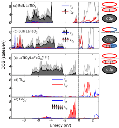
The atomic and orbital projected density of states (DOS) of a (1/1) LaTiO3/LaFeO3 superlattice are shown in Figs. 1c-e. At the interface, the non-bonding oxygen bands of LaTiO3 and LaFeO3 align (Fig. 1c), the Ti 3d bands are empty (Fig. 1d) and 6 electrons are located in the Fe 3d band (Fig. 1e). This means that one electrons is transferred from Ti to Fe, resulting in Ti4+ and Fe2+. In addition, a rearrangement of the Fe 3 bands in the LaTiO3/LaFeO3 superlattice is observed. Here, a completely filled Fe t2g band is located above the O 2p band and the Fe eg band is empty (Fig. 1e), while in bulk the filled lower Hubbard band of Fe is below the O 2p band (Fig. 1b). Due to the electron transfer and band rearrangement, a band insulator (BI) with a gap between the filled Fe t2g and the empty Ti t2g bands (B0.5 eV) is formed at the interface Zaanen et al. (1985). In addition, the DFT results point to a magnetic transition: from Ti3+() and high spin Fe3+ (3, 2) configuration in bulk to Ti4+ and low spin Fe2+ (3, 3) configuration (i.e. non-magnetic) at the interface. To ensure that the observed charge transfer depended on the presence of partially filled d bands on both sides of the interface, we also calculated (1/1) and (2/2) LaAlO3/LaFeO3 superlattices. Here, no electron transfer or magnetic transition occurs, since Al has an empty 3d band well above the Fermi energy, which fixes the Al valence strictly to 3+ (see also Fig. 1 of Supplemental Material) Sup .
According to the DFT results, the observed charge transfer at the LaTiO3/LaFeO3 interface is very robust. Increasing the thickness of LaFeO3 to 4 u.c., slightly straining of the unit cells, or varying UTi,Fe between 0 and 5 eV does not eliminate the observed transfer of one electron per interface unit cell. Moreover, investigating a (2/4) LaTiO3/LaFeO3 superlattice, it appears that the majority of transferred electron remains at the LaFeO3 interface layer (Fig.2c-e of Supplemental Material Sup ). The layers further away from the interface, closely resemble the bulk DOS of LaFeO3 (Fig. 1b). Let us note that the interface charge transfer is very robust and reliable for any LaFeO3 thickness. Even LaTiO3/LaFeO3 heterostructures without structural distortions show this one electron charge transfer (See Supplemental Material Sup ). Since the charge transfer may lead to complex physical behavior in LaFeO3, as a result of the competition of various magnetic configurations (bulk vs. interface), it is difficult to accurately determine the magnetic and electronic state of interfaces where LaFeO3 2 u.c.
The DFT results indicated that the interfacial electron transfer at LaTiO3/LaFeO3 interfaces is the consequence of (i) electrochemical potential, also described as O band alignment, and (ii) crystal field splitting and Hund’s exchange. Taking only the O band alignment into account, electrons flow from Ti to Fe and reduce their electrochemical potential. As a result, an internal electric field, which balances the electrochemical potential difference between Ti and Fe, is created and prevents further charge transfer. This is also the reason why charge transfer at oxide interfaces is not evident when it only relies on O band alignment Zubko et al. (2011). In LaTiO3/LaFeO3, however, an additional force comes into play, namely a rearrangement of the Fe 3d bands. The origin of this rearrangement is a high-spin to low-spin transition which is a result of the competition between Hund’s exchange and crystal field splitting (see Supplemental Material Sup ). This makes the low-spin configuration energetically more favorable for Fe2+ and yields an additional energy gain for the charge transfer. As a result, a strong electron transfer is observed at the LaTiO3/LaFeO3 interface and accompanied by a loss of magnetic moment.
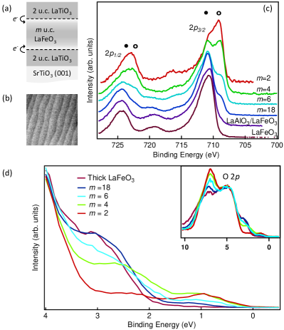
To resolve the predicted charge transfer and band rearrangement experimentally, we used XPS. XPS is very sensitive to variations in the valence state of transition metal ions and able to detect the valence band structure. Therefore, it is a perfectly suited technique to determine the presence of both charge transfer and band rearrangement at the LaTiO3/LaFeO3 interface. We have studied LaTiO3/LaFeO3 heterostructures where the LaFeO3 layer (m = 2, 4, 6, 18 u.c.) was sandwiched between two LaTiO3 layers, each 2 u.c. thick (see Fig. 2a). The heterostructures were grown on TiO2-terminated SrTiO3 (001) single crystals using pulsed laser deposition Koster et al. (1998). Commercial LaFeO3 and La2Ti2O7 sintered targets were ablated at a fluence of 1.9 Jcm-2 and a repetition rate of 1 Hz. During growth, the substrate was held at 730 ∘C in 210-6 mbar oxygen atmosphere. Subsequently, the samples were cooled down to room temperature in 210-6 mbar oxygen. The low growth pressure was chosen to ensure the fabrication of the perovskite phase of LaTiO3 Ohtomo et al. (2002b).
The growth was in situ monitored by reflection high-energy electron diffraction (RHEED). Clear oscillations were observed during deposition and the RHEED pattern remained two dimensional 111Note that some Ti/Fe intermixing across the interface may be present, taking the low oxygen pressure during growth into account Willmott et al. (2007).. Atomically smooth film surfaces with a defined terrace structure and one unit cell steps (0.4 nm) were confirmed by atomic force microscopy (AFM) (see Fig. 2b). X-ray diffraction reciprocal space maps showed that the heterostructures were fully strained and that the LaTiO3 and LaFeO3 u.c. volumes were similar to their bulk values. The volume conservation indicates that the heterostructures had a low defect density. The possible conducting behavior of the heterointerfaces could not be verified since the transport measurements were dominated by oxygen deficient SrTiO3 as a result of the low pressure during growth and cool down.
Directly after growth, the LaTiO3/LaFeO3 heterostructures were measured by in situ XPS (see Fig 2c and 2d). The XPS system was equipped with an EA 125 electron energy analyzer. The measurements were done using a monochromized Al K source (1486.6 eV). All spectra were aligned to the O 1s at 530.1 eV 222No charging of the samples was observed during X-ray exposure since the SrTiO3-δ became conducting as a result of the low oxygen pressure during growth and cool down.. For analysis of the Fe 2p spectra, a Shirley background was subtracted and the spectra were normalized to the total area 333The La MNN (at 740-800 eV) obscures the Fe 2p satellite structure at higher binding energy. To allow proper normalization, we limited the Fe 2p range up to this satellite peak.. The valence band spectra were normalized to the intensity of the O 2p peak at 5 eV 444Normalization of the valence band spectra is complicated by the Ti-O 2p and Fe-O 2p hybridization. To allow for a qualitative analysis, the valence band spectra were aligned on the intensity of the O 2p at 5 eV. However, this may result in minor normalization artefacts..
Fig. 2c shows the Fe 2p spectra of LaTiO3/LaFeO3 heterostructures and a 30 u.c. thick LaFeO3 film. The LaFeO3 film exhibits a typical Fe3+ spectrum Fujii et al. (1999). For the LaTiO3/LaFeO3 heterostructures, additional spectral weight is present at 2 eV lower binding energy. This suggests that both Fe3+ and Fe2+ are present in the heterostructures and indicates that Fe reduction occurs adjacent to LaTiO3. For comparison, only Fe3+ is observed in LaFeO3 (m=2) sandwiched between LaAlO3 layers (Fig 2c). Reducing the thickness of the LaFeO3 layer in the heterostructures resulted in an increase of the Fe2+ signal, which confirms the DFT prediction that electron transfer occurs at LaTiO3/LaFeO3 interfaces. We also measured the Ti 2p spectra of the heterostructures to determine the presence of both Ti3+ to Ti4+. Here, however, only a single peak for both the Ti 2p3/2 (at 459 eV) and Ti 2p1/2 spin-orbit peaks is observed. This could indicate a single Ti valence of presumably 4+ and hence complete charge transfer from Ti to Fe across the interface, independent of LaFeO3 thickness in agreement with our DFT+U calculations (see Supplemental Material Sup ) Kareev et al. (2013).
To quantify the total number of electrons transferred from LaTiO3 to LaFeO3 as well as the electron distribution across the LaFeO3 layer, we performed angular resolved XPS measurements. By varying the emission angle with respect to the surface normal, we controlled the probing depth, i.e. controlled the effective electron escape depth =, where is approximately 1.7 nm (see inset Fig. 3) NIS . Next, we determined the Fe2+ and Fe3+ fractions of the Fe 2p spectra by decomposing the Shirley corrected spectra into an Fe2+ and Fe3+ component (see for more details Supplemental Material Sup ). This resulted in a window of Fe2+ XPS signal for bulk (=3∘) and surface (=53∘) sensitive measurements, which is shown in Fig. 3. Both the decrease in spectral weight of Fe2+ for increasing LaFeO3 thickness and the stronger Fe2+ signal in the surface sensitive measurements suggest that the transferred electrons are located near the LaTiO3/LaFeO3 interface. Note that the difference between the bulk and surface sensitive measurement for the m=2 LaTiO3/LaFeO3 heterostructure would not be present if both LaTiO3/LaFeO3 interfaces behaved equally. For this specific sample, however, the deposition length of the top LaTiO3 layer was 7% (2 pulses) longer than for the bottom LaTiO3 layer. This may explain the difference between the bulk and surface sensitive measurements. In addition, the underlying SrTiO3/LaTiO3 interface may also reduce the total electron transfer from the bottom LaTiO3 layer to the LaFeO3 layer Ohtomo et al. (2002a).
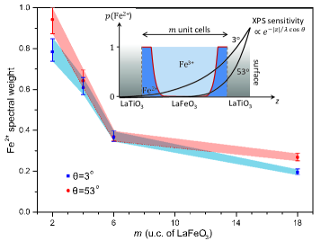
Subsequently, we determined the total electron transfer and electron distribution by modelling the thickness dependence of the spectral weight of Fe2+ shown in Fig. 3. This was done by iteratively optimizing the electron doping in the five LaFeO3 layers nearest to the interface with LaTiO3 between 0 and 1 (for more details see Supplemental Material Sup ). This model confirmed that the majority of transferred electrons was located in the LaFeO3 layer closest to the interface as well as that the number of electrons rapidly decreased for layers further away from the interface (see inset Fig. 3). These findings are in good agreement with our DFT results, where for thicker LaFeO3 layers also a minor part of the electrons is transferred to the LaFeO3 layers away from the interface (see Supplemental Material Fig. 2e Sup ). In addition, the model gave an indication of the total electron transfer, from 0.81.0 e-/interface u.c. for m = 2 heterostructures to 1.11.4 e-/interface u.c. for heterostructures with m 10. The total electron transfer being 1 e-/interface u.c. indicates that additional electrons are transferred from the LaTiO3 layers further away from the interface. This is also suggested by our DFT results taking Ti surface states into account (see Supplemental Material Sup ). In comparison to our DFT results, the total charge transfer observed experimentally is significantly higher. However, for the DFT calculations a (1/1) system was used, thus all LaTiO3 layers being adjacent to LaFeO3, and therefore, the number of transferred electrons could not exceed 1 e-/interface u.c. Let us note that possible Ti/Fe intermixing across the interface may affect the exact electron distribution and total charge transfer, but does not change the essential interface physics (see also Supplemental Material Sup ).
Next to electron transfer, our DFT calculations predict rearrangement of the Fe 3d bands. To study this rearrangement, we measured the valence band spectra by XPS (Fig. 2d) 44footnotemark: 4. Comparing the spectra of LaTiO3/LaFeO3 heterostructures with the spectra of the thick LaFeO3 film, a new peak at 1 eV is present for the heterostructures. According to the DFT calculations, this new peak is attributed to the completely filled t2g band of Fe2+. The intensity of this peak depends on the number of strongly electron doped LaFeO3 layers near the surface. Taking the electron distribution in LaFeO3 into account, the first two LaFeO3 layers nearest to the LaTiO3/LaFeO3 interface would mainly contribute to the spectral weight of this peak. This also explains the similar peak intensity for the m=2 and m=4 heterostructures, but reduced intensity for the thicker heterostructures. Simultaneously, the charge transfer band of LaFeO3, resulting from the O 2p-Fe eg hybridization, decreases in intensity. This strongly supports the occurrence of Fe band rearrangement at the LaTiO3/LaFeO3 interface predicted by DFT. The presence of Fe band rearrangement strongly indicates that the interfaces become non-magnetic, as proposed by our DFT calculations. In addition, the Ti 3d1 band near the Fermi level may be present in the valence band spectra. However, the resulting changes in the Ti 3d occupation of the LaTiO3 layers are difficult to extract from the spectra shown in Fig. 2d, as the Ti 3d1 peak is very weak and probably obscured by the appearance of the new Fe peak Takizawa et al. (2006).
In conclusion, we have shown that the competition between electrochemical potential, crystal field splitting and correlation energy can lead to an unprecedented transfer of electrons at LaTiO3/LaFeO3 interfaces. Using XPS, we showed a charge transfer up to 1.20.2 e-/interface u.c. from Ti to Fe as well as the rearrangement of the Fe 3d bands. For LaTiO3/LaFeO3, the charge transfer suppresses the magnetic moment and antiferromagnetism at the interface. Considering the basic electronic configuration, we expect however the interfaces of e.g. LaTiO3/LaMnO3 and LaTiO3/LaCoO3 to become ferromagnetic upon charge transfer. Moreover, by applying biaxial strain, it may be possible to control the number of transferred electrons and, with it, the interfacial properties. Hence, the reported charge transfer up to 1.20.2 e-/interface u.c. opens novel routes to design functional oxide interfaces.
The authors thank B. Kuiper for valuable technical help. G.R. thanks the financial support by The Netherlands Organization for Scientific Research (NWO) through a VIDI grant. R.C. and K.H. acknowledge support from Research Unit FOR 1346 of the Deutsche Forschungsgemeinschaft and the Austrian Science Fund (project ID I597), respectively.
References
- Ueda et al. (1999) K. Ueda, H. Tabata, and T. Kawai, Phys. Rev. B 60, R12561 (1999).
- Gozar et al. (2008) A. Gozar, G. Logvenov, L. Fitting Kourkoutis, A. T. Bollinger, L. A. Giannuzzi, D. A. Muller, and I. Bozovic, Nature 455, 782 (2008).
- Ohtomo and Hwang (2004) A. Ohtomo and H. Y. Hwang, Nature 427, 423 (2004).
- Ohtomo et al. (2002a) A. Ohtomo, D. A. Muller, J. L. Grazul, and H. Y. Hwang, Nature 419, 378 (2002a).
- Moetakef et al. (2011) P. Moetakef, T. A. Cain, D. G. Ouellette, J. Y. Zhang, D. O. Klenov, A. Janotti, C. G. Van de Walle, S. Rajan, S. J. Allen, and S. Stemmer, Appl. Phys. Lett. 99, 232116 (2011).
- Okamoto and Millis (2004) S. Okamoto and A. Millis, Nature 428, 630 (2004).
- Nakagawa et al. (2006) N. Nakagawa, H. Y. Hwang, and D. A. Muller, Nat. Mater. 5, 204 (2006).
- Noguera (2000) C. Noguera, J. Phys.: Condens. Matter. 12, R367 (2000).
- Kalabukhov et al. (2007) A. Kalabukhov, R. Gunnarsson, J. Börjesson, E. Olsson, T. Claeson, and D. Winkler, Phys. Rev. B 75, 121404 (2007).
- Siemons et al. (2007) W. Siemons, G. Koster, H. Yamamoto, W. A. Harrison, G. Lucovsky, T. H. Geballe, D. H. A. Blank, and M. R. Beasley, Phys. Rev. Lett. 98, 196802 (2007).
- Zhong et al. (2010) Z. Zhong, P. X. Xu, and P. J. Kelly, Phys. Rev. B 82, 165127 (2010).
- Chen et al. (2011) Y. Chen, N. Pryds, J. E. Kleibeuker, G. Koster, J. Sun, E. Stamate, B. Shen, G. Rijnders, and S. Linderoth, Nano Lett. 11, 3774 (2011).
- Zaanen et al. (1985) J. Zaanen, G. A. Sawatzky, and J. W. Allen, Phys. Rev. Lett. 55, 418 (1985).
- Arima et al. (1993) T. Arima, Y. Tokura, and J. B. Torrance, Phys. Rev. B 48, 17006 (1993).
- Chen et al. (2013) H. Chen, A. J. Millis, and C. A. Marianetti, Phys. Rev. Lett. 111, 116403 (2013).
- Blochl (1994) P. E. Blochl, Phys. Rev. B 50, 17953 (1994).
- Kresse and Joubert (1999) G. Kresse and D. Joubert, Phys. Rev. B 59, 1758 (1999).
- Dudarev et al. (1998) S. L. Dudarev, G. A. Botton, S. Y. Savrasov, C. J. Humphreys, and A. P. Sutton, Phys. Rev. B 57, 1505 (1998).
- Tokura et al. (1993) Y. Tokura, Y. Taguchi, Y. Okada, Y. Fujishima, T. Arima, K. Kumagai, and Y. Iye, Phys. Rev. Lett. 70, 2126 (1993).
- Koehler et al. (1960) W. C. Koehler, E. O. Wollan, and M. K. Wilkinson, Phys. Rev. 118, 58 (1960).
- Pavarini et al. (2004) E. Pavarini, S. Biermann, A. Poteryaev, A. I. Lichtenstein, A. Georges, and O. K. Andersen, Phys. Rev. Lett. 92, 176403 (2004).
- Zhong and Kelly (2008) Z. Zhong and P. J. Kelly, Eur. Phys. Lett. 84, 27001 (2008).
- (23) See for more details Supplemental Materials.
- Zubko et al. (2011) P. Zubko, S. Gariglio, M. Gabay, P. Ghosez, and J.-M. Triscone, Annu. Rev. Conden. Ma. P. 2, 141 (2011).
- Koster et al. (1998) G. Koster, B. L. Kropman, G. J. H. M. Rijnders, D. H. A. Blank, and H. Rogalla, Appl. Phys. Lett. 73, 2920 (1998).
- Ohtomo et al. (2002b) A. Ohtomo, D. A. Muller, J. L. Grazul, and H. Y. Hwang, Appl. Phys. Lett. 80, 3922 (2002b).
- Note (1) Note that some Ti/Fe intermixing across the interface may be present, taking the low oxygen pressure during growth into account Willmott et al. (2007).
- Note (2) No charging of the samples was observed during X-ray exposure since the SrTiO3-δ became conducting as a result of the low oxygen pressure during growth and cool down.
- Note (3) The La MNN (at 740-800 eV) obscures the Fe 2p satellite structure at higher binding energy. To allow proper normalization, we limited the Fe 2p range up to this satellite peak.
- Note (4) Normalization of the valence band spectra is complicated by the Ti-O 2p and Fe-O 2p hybridization. To allow for a qualitative analysis, the valence band spectra were aligned on the intensity of the O 2p at 5 eV. However, this may result in minor normalization artefacts.
- Fujii et al. (1999) T. Fujii, F. M. F. de Groot, G. A. Sawatzky, F. C. Voogt, T. Hibma, and K. Okada, Phys. Rev. B 59, 3195 (1999).
- Kareev et al. (2013) M. Kareev, Y. Cao, X. Liu, S. Middey, D. Meyers, and J. Chakhalian, Appl. Phys. Lett. 103, 231605 (2013).
- (33) NIST standard reference database 71, version 2.1.
- Takizawa et al. (2006) M. Takizawa, H. Wadati, K. Tanaka, M. Hashimoto, T. Yoshida, A. Fujimori, A. Chikamatsu, H. Kumigashira, M. Oshima, K. Shibuya, T. Mihara, T. Ohnishi, M. Lippmaa, M. Kawasaki, H. Koinuma, S. Okamoto, and A. J. Millis, Phys. Rev. Lett. 97, 057601 (2006).
- Willmott et al. (2007) P. R. Willmott, S. A. Pauli, R. Herger, C. M. Schlepütz, D. Martoccia, B. D. Patterson, B. Delley, R. Clarke, D. Kumah, C. Cionca, and Y. Yacoby, Phys. Rev. Lett. 99, 155502 (2007).