Pathfinder flight of the Polarized Gamma-ray Observer (PoGOLite) in 2013
Abstract
The Polarized Gamma-ray Observer (PoGOLite) is a balloon-borne instrument that can measure polarization in the energy range 25–240 keV. The instrument adopts an array of well-type ”phoswich” detectors in order to suppress backgrounds. Based on the anisotropy of Compton scattering angles resulting from polarized gamma-rays, the polarization of the observed source can be reconstructed. During July 12-26 of 2013, a successful near-circumpolar pathfinder flight was conducted from Esrange, Sweden, to Norilsk, Russia. During this two-week flight, several observations of the Crab were conducted. Here, we present the PoGOLite instrument and summarize the 2013 flight. tkawano@hep01.hepl.hiroshima-u.ac.jp.
I Measuring polarization
Astrophysical phenomena can be observed with electromagnetic radiation by imaging, spectroscopy, timing analysis, and polarimetry. Since X-ray observations began 50 years ago, many observatories have provided data for imaging, spectroscopy, and timing analyses. On the other hand, polarization measurements of X-rays and gamma-rays have been technically difficult and only a few sensitive observations have been performed. Polarized X-rays and gamma-rays are expected to be emitted from a wide variety of astronomical sources, including pulsars, X-ray binary systems, strongly magnetized neutron stars, collimated outflows from active galactic nuclei and gamma-ray bursts. Therefore, polarimetric studies of these sources are expected to provide important new insight into the physics of such highly energetic objects. In particular, it is important to understand the acceleration site and magnetic field structure of pulsars and their surrounding wide nebulae by identifying the emission mechanisms with polarimetry.
II Target object: the Crab nebula
II.1 Outline
The Crab nebula is a remnant of the historical supernova in 1054 A.D., located around 2 kpc from the Earth. This celestial object is named ”Crab nebula” after the characteristic filament structure in optical wavelengths, and it has been studied intensively in all wavelengths from radio to gamma-rays since the early days of astronomy. The Crab consists of a pulsar, a synchrotron nebula and a bright expanding shell of thermal gas. We can also see a highly collimated bipolar outflow (jet), which is aligned to the spin axis of the pulsar, as well as a circumstellar torus visible in X-rays. The high-energy emission is brightest near the center of the nebula.
The Crab pulsar is considered as a neutron star with a radius of 10 km, a mass of 1.4 , a rotation period P = 33 ms, = 4.21 10-13, magnetic field B 1012 G, and spin-down luminosity 5 1038 erg/s. The strong magnetic field and short rotation period produce a relativistic outflow of electron-positron pairs which is called the pulsar wind. This ultrarelativistic outflow is confined by the thermal ejecta. The inner ring of the nebula, reported to be at a distance of about 3 1017 cm from the pulsar, corresponds to a termination shock, created when the pulsar wind interacts with the surrounding synchrotron nebula. It is considered that the pulsar wind and possibly other particles are accelerated to energies as high as 1016 eV at the termination shock. High energy charged particles interact with the magnetic field in the nebula (a few mG), and emit synchrotron radiation. The X-ray emission becomes softer toward the outer region owing to adiabatic and radiative losses. At the edge of the nebula, there are only low-energy radio-emitting electrons. The spectrum of X-rays and gamma-rays below 1 GeV for the Crab nebula is well described by synchrotron emission, and inverse Compton scattering dominates above 1 GeV Hester (2008).
II.2 Previous polarization measurements of the Crab nebula
Measurement by OSO-8
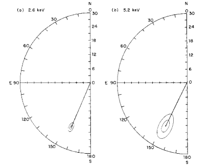
The OSO-8 satellite carried an X-ray polarimeter consisting of a panel of mosaic graphite crystals, which were utilized for Bragg reflection Weisskopf et al. (1978).
The polarization fraction of the Crab nebula observed by OSO-8 was (19.19 0.97)% with (156.36 1.44)∘ polarization angle at 2.6 keV, and (19.50 2.77)% polarization fraction with (152.59 4.04)∘ polarization angle at 5.2 keV, where the errors correspond to 67% confidence contours. These results are in agreement with optical polarization measurements (FIG. 1) Weisskopf et al. (1978).
Observation by INTEGRAL/SPI
The SPI (spectrometer onboard INTEGRAL; INTErnational Gamma-Ray Astrophysics Laboratory) has a capability for polarization measurements using Compton scattering Kalemci et al. (2004).
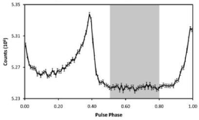
A polarization analysis of the Crab nebula was performed with data recorded from February 2003 to April 2006, and only events during the off-pulse fraction of the pulsar cycle were included (FIG. 2 top).
A polarization fraction of (46 10)% was observed, with the polarization angle (123 11)∘, which is closely aligned with the pulsar spin axis ((124 0.1)∘) (FIG. 2 bottom), but the errors are dominated by systematic effects. The observed alignment of the polarization axis with the jet axis suggests an orthogonal magnetic field configuration towards the jet axis if the soft gamma-ray emission is caused by synchrotron emission. The observed polarization fraction is quite high, but less than the maximum limit for synchrotron radiation, 75% Dean et al. (2008)Chauvin et al. (2013).
Observation by INTEGRAL/IBIS
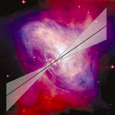
The IBIS (imager on INTEGRAL) is also using Compton scattering for polarimetry Forot et al. (2008). Also this instrument has been used to study the polarization of the Crab.
The results are shown with respect to the pulsar phase (FIG. 2 top). For the ”off-pulse” phase and ”off-pulse and bridge” phase, the polarization fraction is reported to be quite high (72%), with the polarization angle aligned along the jet axis (FIG. 3). This result suggests that the off-pulse polarized emission recorded above 200 keV can come from a striped wind, jets, and/or equatorial wind near the bright knot. The magnetohydrodynamics models predict that the polarization is strongest at the pulsar, in the knot, and along the jets, and it should be mostly parallel to the rotation axis Forot et al. (2008).
III The PoGOLite balloon-borne instrument
III.1 Overview
PoGOLite (Polarized Gamma-ray Observer Light-weight version) is a balloon-borne Compton polarimeter (FIG. 4), measuring the polarization of hard X-rays/soft gamma-rays from celestial objects in the energy range 25–240 keV mozsi . Polarization in the 25–100 keV energy band has not been observed previously.
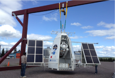
Observational targets for PoGOLite include the Crab and Cygnus X-1, and the instrument is able to detect 10% liner polarization from the Crab nebula for 15-hour exposure time with the 99% confidence, in a signal-to-background scenario of 1:1. The detector is optimized for point sources, with a narrow field of view of 2.4∘ 2.6∘, and the required pointing precision is 0.1∘. Since radiation from sources follows an inverse power-law and photons are additionally absorbed in the atmosphere, a high float altitude of the instrument (40 km) and sensitivity extending as low as possible are crucial. The collaboration is international, involving institutes and universities from Japan111Hiroshima University, Tokyo Institute of Technology, Yamagata University, Japan Aerospace Exploration Agency (JAXA)., Sweden222Royal Institute of Technology (KTH), Stockholm University (SU)., and the United States333Stanford Linear Accelerator Center (SLAC), Kavli Institute for Particle Astrophysics and Cosmology (KIPAC), University of Hawaii..
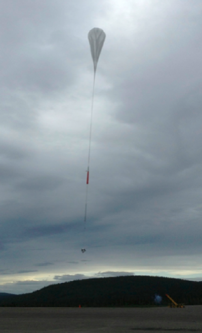
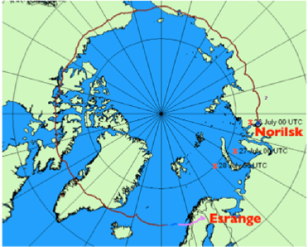
The full-size version of PoGOLite consists of 217 units. It is intended to be able to measure as low as 10% polarization from a 200 mCrab source in a six-hour flight Kamae et al. (2008). The 61-unit ”Pathfinder” version of PoGOLite has been prepared for launch from Esrange in northen Sweden in 2011, 2012 and 2013. In this paper, we simply refer to the ”PoGOLite Pathfinder” as ”PoGOLite”. On July 6th, 2011 (UTC), the payload was launched for a flight with a foreseen landing in Canada (duration 5 days). However, there was a leak of helium from the balloon, and the gondola was returned to ground after 5 hours. A second launch was foreseen in July 2012, but had to be cancelled due to unfavorable weather conditions. PoGOLite was successfully launched from Esrange, Sweden, on July 12th at 0818 UT in 2013 (FIG. 5). A circumpolar flight was possible thanks to permission received from Russian authorities. The flight ended on July 26th when the gondola touched down close to the Siberian city of Norilsk (3000 km to the East of Moscow) at 0015 UT.
III.2 Detector configuration
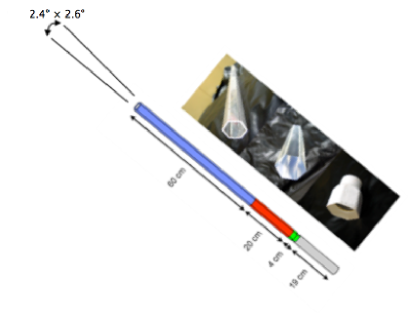
To suppress the high rate of background events at float altitude (40 km), we adopted an array of 61 well-type phoswich detector cells (PDCs) surrounded by a segmented BGO (bismuth germanate oxide, Bi4Ge3O12) anticoincidence shield comprising 30 units. A LiCAF (LiCAl6) neutron-sensitive scintillator Takahashi et al. (2014) is also included (FIG. 6 top). Each PDC consists of three active components: a hollow ”slow” plastic scintillator (60 cm), a solid ”fast” plastic scintillator (20 cm), and a BGO crystal (4 cm), read out by a photomultiplier tube (from Hamamatsu Photonics, 19 cm) (FIG. 6 bottom). The LiCAF scintillator is made for neutron detection since neutrons are expected to dominate the background. This detector is sandwiched between two BGO elements for rejecting gamma-rays, allowing neutron interactions to be distinguished.
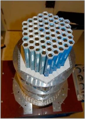
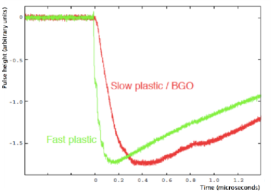
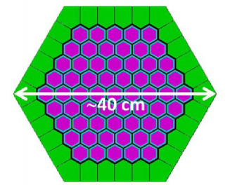
The photomultiplier tube waveforms are sampled at a 37.5 MHz rate and digitized with to 12 bit accuracy. The ”fast” scintillator, ”slow” scintillator and BGO crystal have different decay times, resulting in different pulse shapes for waveforms originating from these components (FIG. 7). By identifying these differences, we can determine in which component an interaction has taken place, allowing background events to be discarded. The PDC units are hexagonal so they can be tightly packed in a honey-comb structure, while surrounding SAS segments have two different pentagonal shapes to fit closely around detector array (FIG. 8).
III.3 Polarimeter design
An indicator of performance of X-ray and gamma-ray polarimeters, which is called as MDP (Minimum Detectable Polarization; degree distinguishable from statistical fluctuation with 3), is written in equation (1).
where is the modulation factor (depends on the instrument geometry and the spectrum of the incident photon flux), is the signal rate, is the background rate and is the exposure time. This represents the minimum polarization fraction measurable by the instrument for the given confidence level Weisskopf et al. (2010). A large , a large , a small , and a large are needed to achieve a low MDP, i.e. good sensitivity to polarization. For a given source, a large corresponds to a large effective area of the instrument.
For PoGOLite, the effective area is 22 cm2, with a reasonable modulation factor (M 26% at 50 keV) Chauvin et al. (Astroparticle Physics Journal submitted).
IV Measuring polarization
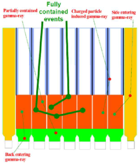
The PoGOLite instrument is using Compton scattering for polarimetry. The procedure is illustrated below (FIG. 9):
-
•
Polarized gamma-rays undergo Compton scattering in a hexagonal array of plastic scintillators.
-
•
Polarized photons tend to scatter perpendicularly to the polarization direction, following equation (2).
-
•
Observed azimuthal scattering angles are modulated by polarization.
where and are the momenta of the incident and scattered photon, respectively, re is the classical electron radius and and correspond to the polar and azimuthal scattering angles. Angle is defined relative to the polarization direction of the incident photon, resulting in a polarization-dependence for the scattering process.
Tracking individual photons through coincident detection of Compton scattering and photoelectric absorption allows the azimuthal scattering angles to be reconstructed. Since photons scatter preferentially perpendicular to the polarization direction, the resulting distribution of scattering angles will be anisotropic (modulated) for a polarized flux of photons.
V Flight trajectory & Results
As mentioned in section III.1, during July 12-26 of 2013, a successful near-circumpolar pathfinder flight was conducted from Esrange, Sweden, to Norilsk, Russia (FIG. 10). During the daytime, the balloon has higher altitude because of heating of the helium inside the balloon. Conversely, the balloon has lower altitude during the night, resulting in a diurnal variation of the pressure.
The attitude control system performance has been evaluated from Crab measurements, and the observed performance was found to be an order of magnitude better than the design requirement of 0.1∘.
We obtained the pulse-folded light curve of the Crab pulsar. The data includes two- and three-hit events in the energy range 20 keV – 110 keV, and we can clearly see the Crab pulsation from the light-curve. This shows that X-ray photons from the Crab pulsar are indeed detected by the polarimeter, confirming that the instrument and attitude control system are working as intended.
VI Summary & Outlook
During July 2013, the PoGOLite Pathfinder made a circumpolar flight (13.5 days) from Esrange. This flight was possible thanks to permission from the Russian government and help from Russian colleagues. We have confirmed that the polarimeter detected the Crab pulsation. Crab polarization results are in preparation. We have a plan to improve the polarimeter design based on the experience from the 2013 flight, to reject background more efficiently. Reflight of PoGOLite is proposed for the summer of 2016.
References
- Chauvin et al. (2013) Chauvin, M., Roques, J. P., Clark, D. J., & Jourdain, E. 2013, Astrophysical Journal, 769, 137
- Chauvin et al. (Astroparticle Physics Journal submitted) Chauvin, M., Florn, H.-G., Jackson, M., Kamae, T., Kawano, T., Kiss, M., Kole, M., Mikhalev, V., Moretti, E., Rydstrm, S., Takahashi, H., Pearce, M., Astroparticle Physics Journal submitted
- Dean et al. (2008) Dean, A. J., Clark, D. J., Stephen, J. B., et al. 2008, Science, 321, 1183
- Forot et al. (2008) Forot, M., Laurent, P., Grenier, I. A., Gouiffès, C., & Lebrun, F. 2008, ApJL, 688, L29
- Hester (2008) Hester, J. J. 2008, ARA&A, 46, 127
- Kalemci et al. (2004) Kalemci, E., Boggs, S., Wunderer, C., & Jean, P. 2004, 5th INTEGRAL Workshop on the INTEGRAL Universe, 552, 859
- Kamae et al. (2008) Kamae, T., Andersson, V., Arimoto, M., et al. 2008, Astroparticle Physics, 30, 72
- (8) Kiss, M., Royal Institute of Technology Doctoral Thesis, ”Pre-flight development of the PoGOLite Pathfinder” (2011), ISBN 978-91-7415-896-0.
- Takahashi et al. (2014) Takahashi, H., Chauvin, M., Fukazawa, Y., et al. 2014, SPIE Proceedings, 9144, 91444I
- Weisskopf et al. (1978) Weisskopf, M. C., Silver, E. H., Kestenbaum, H. L., Long, K. S., & Novick, R. 1978, ApJL, 220, L117
- Weisskopf et al. (2010) Weisskopf, M. C., Elsner, R. F., & O’Dell, S. L. 2010, SPIE Proceedings, 7732, 77320E